Sony ZRD-1 User manual

DISPLAY UNIT
ZRD-1
ZRD-2
SERVICE MANUAL
1st Edition (Revised 3)

ZRD-1/ZRD-2
!警告
このマニュアルは,サービス専用です。
お客様が,このマニュアルに記載された設置や保守,点検,修理などを行うと感電や火災,
人身事故につながることがあります。
危険をさけるため,サービストレーニングを受けた技術者のみご使用ください。
!WARNING
This manual is intended for qualified service personnel only.
To reduce the risk of electric shock, fire or injury, do not perform any servicing other than that
contained in the operating instructions unless you are qualified to do so. Refer all servicing to
qualified service personnel.
!WARNUNG
Die Anleitung ist nur für qualifiziertes Fachpersonal bestimmt.
Alle Wartungsarbeiten dürfen nur von qualifiziertem Fachpersonal ausgeführt werden. Um die
Gefahr eines elektrischen Schlages, Feuergefahr und Verletzungen zu vermeiden, sind bei
Wartungsarbeiten strikt die Angaben in der Anleitung zu befolgen. Andere als die angegeben
Wartungsarbeiten dürfen nur von Personen ausgeführt werden, die eine spezielle Befähigung
dazu besitzen.
!AVERTISSEMENT
Ce manual est destiné uniquement aux personnes compétentes en charge de l’entretien. Afin
de réduire les risques de décharge électrique, d’incendie ou de blessure n’effectuer que les
réparations indiquées dans le mode d’emploi à moins d’être qualifié pour en effectuer d’autres.
Pour toute réparation faire appel à une personne compétente uniquement.
安全のために,周辺機器を接続する際は,過大電圧を
持つ可能性があるコネクターを以下のポートに接続し
ないでください。
.IN コネクター
.OUT コネクター
上記のポートについては本書の指示に従ってください。
For safety, do not connect the connector for pe-
ripheral device wiring that might have excessive
voltage to the following ports.
.IN connector
.OUT connector
Follow the instructions for the above ports.
Caution (for AC operated products only)
RISK OF ELECTRICK SHOCK
The fuse in primary circuit is/could be in the neu-
tral.
The mains shall be disconnected to de-energize
the phase conductors.
Attention (pour les produits à alimentation CA
uniquement)
RISQUE D’ÉLECTROCUTION
Le fusible du circuit primaire est/doit être en posi-
tion neutre.
L’alimentation secteur doit être déconnectée pour
mettre hors tension les conducteurs de phase.

1 (E)
ZRD-1/ZRD-2
Table of Contents
Manual Structure
Purpose of this manual............................................................ 3 (E)
Related manuals...................................................................... 3 (E)
Trademarks.............................................................................. 3 (E)
1. Service Overview
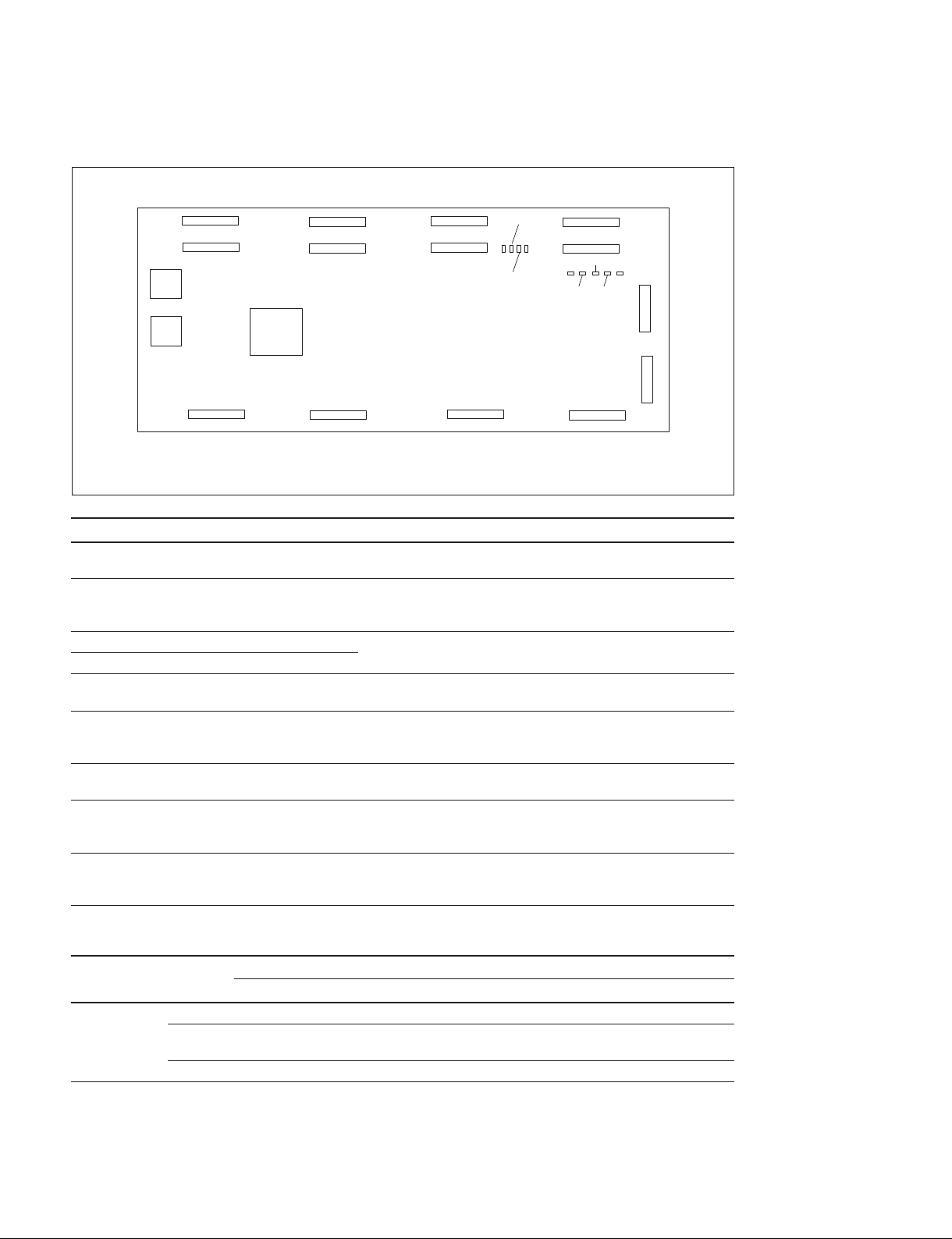
1-1. Parts Location............................................................ 1-1 (E)
1-2. Circuit Protective Parts..............................................1-2 (E)
1-2-1. Circuit Protective Elements .............................1-2 (E)
1-2-2. Fuse..................................................................1-2 (E)
1-3. Description of Indicators on the Board .....................1-3 (E)
1-3-1. PS-903 Board...................................................1-3 (E)
1-3-2. UC-1 Board......................................................1-4 (E)
1-3-3. UI-24 Board .....................................................1-5 (E)
1-3-4. UP-13 Board ....................................................1-6 (E)
1-4. Disconnecting/Connecting Flexible Flat Cable.........1-7 (E)
1-5. Tools and Software for Service .................................1-9 (E)
1-6. Lead-free Solder........................................................1-9 (E)
1-7. Precautions on Display Unit................................... 1-10 (E)
2. Periodic Replacement Parts and Cleaning
2-1. Periodic Replacement Parts....................................... 2-1 (E)
2-2. Cleaning ....................................................................2-2 (E)
2-2-1. Display Unit Surface........................................ 2-2 (E)
2-2-2. Air Intake Hole, Exhaust Hole, Fan................. 2-2 (E)
3. Troubleshooting
3-1. First Step When a Trouble Occurs ............................ 3-1 (E)
3-2. Failure Diagnosis.......................................................3-2 (E)
3-2-1. Whole Troubleshooting ...................................3-2 (E)
3-2-2. Trouble in a Display Unit ................................3-4 (E)
3-2-3. Cell Trouble Without System Error .................3-5 (E)
3-2-4. Cell Trouble With Power System Error ...........3-6 (E)
3-2-5. Cell Trouble Without Power System
Error.................................................................3-6 (E)
3-2-6. Temperature Error............................................3-7 (E)
3-2-7. Display Unit System Error............................... 3-8 (E)
3-3. Error Indication .........................................................3-9 (E)
3-3-1. Error Indication by Indicator ...........................3-9 (E)
3-3-2. Error Indication on Display Control
Software......................................................... 3-11 (E)
3-3-3. Error Indication on Color Uniformity
Alignment Software....................................... 3-11 (E)
3-3-4. Error Code List ..............................................3-12 (E)
3-3-5. Warning Code List ......................................... 3-17 (E)
4. Replacement of Parts
4-1. General Information before Replacement.................4-1 (E)
4-1-1. Guide of Removal............................................4-1 (E)
4-1-2. How to Distinguish the Captive Screw............4-2 (E)
4-2. Tightening Torque .....................................................4-3 (E)
4-3. Replacement of Fan................................................... 4-4 (E)
4-4. Replacement of PS-903 Board .................................. 4-6 (E)
4-5. Removal of Rear Cover Assembly ............................4-8 (E)
4-6. Replacement of TM-62 Board................................. 4-11 (E)
4-7. Replacement of UI-24 Board ..................................4-12 (E)
4-8. Replacement of UP-13 Board .................................4-13 (E)
4-9. Replacement of UC-1 Board...................................4-14 (E)
4-10. Replacement of Cell Assembly ...............................4-18 (E)
5. Software Update
6. Circuit Description
6-1. Overall Block Diagram (Simplified).........................6-1 (E)
6-2. Outline of Signal Input and Output...........................6-1 (E)
6-3. Board Functions ........................................................6-1 (E)
6-3-1. Board Functions...............................................6-1 (E)
6-3-2. UC-1 Board......................................................6-2 (E)
6-3-3. UP-13 Board ....................................................6-2 (E)
6-3-4. PS-903 Board...................................................6-2 (E)
6-3-5. UI-24 Board .....................................................6-2 (E)
6-3-6. TM-62 Board ...................................................6-2 (E)

2 (E) ZRD-1/ZRD-2
7. Spare Parts
7-1. Notes on Repair Parts...................................................... 7-1
7-2. Exploded Views............................................................... 7-2
Cover ............................................................................... 7-2
Main Board...................................................................... 7-4
Cell Base and Joint Unit..................................................7-6
Harness ............................................................................ 7-8
7-3. Packing Materials & Supplied Accessories.....................7-9
8. Diagrams
8-1. Overall Block Diagrams..................................................8-1
Overall............................................................................. 8-1
8-2. Frame Wiring................................................................... 8-2
Frame Wiring................................................................... 8-2
Revision History

3 (E)
ZRD-1/ZRD-2
Manual Structure
Purpose of this manual
This manual is the Service Manual of the Display Unit ZRD-1/ZRD-2.
This manual describes the information on the premise of providing the block level
service such as service overview, troubleshooting, replacement of parts, circuit
description, spare parts, and overall block diagram.
Related manuals
In addition to this Service Manual the following manuals are provided.
.Operating Instructions (available on request)
This manual is necessary for application and operation of this unit.
.Installation Manual (available on request)
This manual describes the information on installing this system.
.ZRCT-100 Service Manual (available on request)
This manual describes the information on the premise of providing the block level
service such as service overview, troubleshooting, replacement of parts, software
update, circuit description, spare parts, and overall block diagram of the display
controller.
.Manual for Color Uniformity Alignment Software (available on request)
This manual describes the information on installing and servicing this system by
using the software for service.
Trademarks
Trademarks and registered trademarks used in this manual are as follows.
.Windows is trademarks or registered trademarks of Microsoft Corporation in the
United States and the other countries.
Other system names, product names, and company names appearing in this manual
are trademarks or registered trademarks of their respective holders.


1-1 (E)
ZRD-1/ZRD-2
Section 1
Service Overview
1-1. Parts Location
UC-1 board
TM-62 board
UP-13 board
PS-903 board
Cell (LED module board)
Joint coma (side)
Joint coma (BTM)
Frame
Fan cover
Cover (GU)
Rear cover
UI-24 board
Fan
Fan
Joint coma (side)
Joint coma (BTM)

1-2 (E) ZRD-1/ZRD-2
1-2. Circuit Protective Parts
1-2-1. Circuit Protective Elements
The thermistor functions as a circuit protective element on the PS-903, UC-1 and UP-13 boards of this
unit. The positive characteristic thermistor increases the internal resistance and limits the current flowing
to the circuits when an overcurrent flows or when the ambient temperature increases and the element
reaches the specified temperature. If the elements operates, turn off the main power and inspect the inter-
nal circuit of this unit. After removing the cause of the equipment abnormality and the temperature of the
element decreases, turn on the power again, and this unit operates normally.
It takes about 1 minute for the elements to cool down after the main power is turned off.
Board name Ref. No. Sony parts No. Parts information
PS-903 TH001 ! 1-804-045-11 Thermistor
UC-1 TH2501 ! 1-803-353-21 Positive characteristic thermistor
Holding current : 0.14 A/20dC
TH2502 ! 1-803-353-21 Positive characteristic thermistor
Holding current : 0.14 A/20dC
UP-13 TH001 ! 1-803-615-21 Positive characteristic thermistor
Holding current : 0.50 A/20dC
TH002 ! 1-771-845-21 Positive characteristic thermistor
Holding current : 0.20 A/20dC
TH003 ! 1-802-108-11 Positive characteristic thermistor
Holding current : 1.50 A/20dC
1-2-2. Fuse
This unit has a fuse for circuit protection. A fuse will blow when abnormality occurs and an overcurrent
flows in this equipment. Be sure to replace an old fuse with the specified fuse as shown below after
removing the foreign substances that may cause the shorts.
Board name Ref. No. Sony parts No. Parts name, Rating
PS-903 F101 ! 1-523-042-51 H.B.C. fuse, 6.3 A/250 V
UC-1 F1501, F1502,
F1503, F1505,
F1506, F1507,
F1508, F1509,
F1510, F1511,
F1512
! 1-576-596-41 Micro fuse (1608 type), 1 A/36 V
F1504 ! 1-576-874-41 Micro fuse (1608 type), 2.5 A/32 V

1-3 (E)
ZRD-1/ZRD-2
1-3. Description of Indicators on the Board
1-3-1. PS-903 Board
Ref. No. Color Name Function
D1011 Green 16V Lit: A voltage of 16 V is output.
Off: A voltage of 16 V is not output.
D2004 Orange 12V Lit: A voltage of 12 V is output.
Off: A voltage of 12 V is not output.
PS-903 board (side A)
D2004
D1011

1-4 (E) ZRD-1/ZRD-2
1-3-2. UC-1 Board
Ref. No. Color Name Function
D2503 Green FPGA Lit: The FPGA (IC2001) configuration has been completed.
Off: The FPGA configuration has not been completed.
D2504 Green 16V Lit: A voltage output of 16 V is normal.
Off: A voltage output of 16 V is abnormal. Or, a voltage of 16 V
is not supplied.
D2512 Green UNIT ON Refer to the following table.
D2514 Red Standby/error
D2515 Orange 12V Lit: A voltage of 12 V is supplied from the PS-903 board.
Off: A voltage of 12 V is not supplied from the PS-903 board.
D2516 Green 16V_RDY_STATUS Lit: 16V_RDY_STATUS is High. Display unit is in power ON
state.
Off: 16V_RDY_STATUS is Low. Display unit is in standby mode.
D2517 Green 16V_RDY Lit: 16V_RDY is High. Display unit is in power ON state.
Off: 16V_RDY is Low. Display unit is in standby mode.
D2518 Green VDD1 Lit: The voltage VDD1 is output. (It is output even with one
system.)
Off: The voltage VDD1 is not output.
D2519 Green VDD2 Lit: The voltage VDD2 is output. (It is output even with one
system.)
Off: The voltage VDD2 is not output.
D2512 and D2514
D2512: Green
Lit Off Blink
D2514: Red Lit During system setup The power is standby state. _
Off The picture is displayed
normally.
The power is not supplied. _
Blink _System error System warning
D2503
D2504
D2512
D2514
D2515
D2516
D2517
D2518
D2519
UC-1 board (side A)

1-5 (E)
ZRD-1/ZRD-2
1-3-3. UI-24 Board
D3001 to D3006: Green
Lit Off Blink
D3007 to D3010:
Red
Lit During system setup The power is standby state. _
Off The picture is displayed
normally.
The power is not supplied. _
Blink _System error System warning
UI-24 board (side B)
D3010 D3009 D3008 D3007
D3001
D3002
D3003
D3004
D3005
D3006
: Connector on the side A

1-6 (E) ZRD-1/ZRD-2
1-3-4. UP-13 Board
Ref. No.
Color Name Function
D1604
Green
Cell driving
power supply
output 1
Lit: VDD1_4 and VDD2_4 are supplying the power to the cell-1
normally.
Off: VDD1_4 and VDD2_4 do not supply the power to the cell-1.
D1605 Cell driving
power supply
output 5
Lit: VDD1_8 and VDD2_8 are supplying the power to the cell-5
normally.
Off: VDD1_8 and VDD2_8 do not supply the power to the cell-5.
D1606 Cell driving
power supply
output 2
Lit: VDD1_3 and VDD2_3 are supplying the power to the cell-2
normally.
Off: VDD1_3 and VDD2_3 do not supply the power to the cell-2.
D1607 Cell driving
power supply
output 6
Lit: VDD1_7 and VDD2_7 are supplying the power to the cell-6
normally.
Off: VDD1_7 and VDD2_7 do not supply the power to the cell-6.
D1608 Cell driving
power supply
output 8
Lit: VDD1_5 and VDD2_5 are supplying the power to the cell-8
normally.
Off: VDD1_5 and VDD2_5 do not supply the power to the cell-8.
D1609 Cell driving
power supply
output 11
Lit: VDD1_10 and VDD2_10 are supplying the power to the
cell-11 normally.
Off: VDD1_10 and VDD2_10 do not supply the power to the cell-11.
D1610 Cell driving
power supply
output 12
Lit: VDD1_9 and VDD2_9 are supplying the power to the cell-12
normally.
Off: VDD1_9 and VDD2_9 do not supply the power to the cell-12.
D1611 Cell driving
power supply
output 4
Lit: VDD1_1 and VDD2_1 are supplying the power to the cell-4
normally.
Off: VDD1_1 and VDD2_1 do not supply the power to the cell-4.
D1612 Cell driving
power supply
output 9
Lit: VDD1_12 and VDD2_12 are supplying the power to the
cell-9 normally.
Off: VDD1_12 and VDD2_12 do not supply the power to the cell-9.
D1613 Cell driving
power supply
output 10
Lit: VDD1_11 and VDD2_11 are supplying the power to the
cell-10 normally.
Off: VDD1_11 and VDD2_11 do not supply the power to the cell-10.
D1614 Cell driving
power supply
output 3
Lit: VDD1_2 and VDD2_2 are supplying the power to the cell-3
normally.
Off: VDD1_2 and VDD2_2 do not supply the power to the cell-3.
D1615 Cell driving
power supply
output 7
Lit: VDD1_6 and VDD2_6 are supplying the power to the cell-7
normally.
Off: VDD1_6 and VDD2_6 do not supply the power to the cell-7.
D1611
D1610
D1609
D1608
UP-13 board (side A)
D1607
D1606
D1605
D1604
D1612
D1613
D1614
D1615
Front view
1234
5678
9 0 !- !=

1-7 (E)
ZRD-1/ZRD-2
1-4. Disconnecting/Connecting Flexible Flat Cable
n
.Be very careful not to fold flexible flat cable. Life of flexible flat cable will be significantly shortened if
it is folded.
.Each flexible flat cable has conductor side and insulated side. If the flexible flat cable is connected in
the wrong orientation of the conductor side and the insulated side, the circuit will not function.
.Insert the flexible flat cable straight.
.Check that the conductive surface of the flexible flat cable is not contaminated.
Flexible flat cable on the UC-1 board
Prepare the following tool for disconnecting the flexible flat cable.
.FFC remover (Part number: 4-689-815-01)
Disconnecting
1. Insert the FFC remover between the lock and the flexible flat cable, and then lower the FFC remover
in the direction of the arrow Ato open the lock.
2. Remove the flexible flat cable.
Connecting
1. Raise the lock.
2. Insert the flexible flat cable as far as it will go.
3. Lower the lock.
Flexible flat cable
FFC remover
Flexible flat cable
Lock
Lock
FFC remover
A
A
Cell UC-1 board
Line in red
Flexible flat cableBlue
Lock
Guide
Guide
Guide

1-8 (E) ZRD-1/ZRD-2
A
Lock
Insulated side
Flexible flat cable
Notes on inserting the flexible flat cable
.Do not insert the flexible flat cable on the skew.
.Do not overlap the flexible flat cable on the guides on the left and right sides.
Flexible flat cable on the cell
Connecting:
1. Raise the lock in the direction of the arrow A.
2. Insert the flexible flat cable as far as it will go.
3. Lower the lock.
Flexible flat cable
Guide
OK NG
Guide
Guide Guide
NG NG

1-9 (E)
ZRD-1/ZRD-2
1-5. Tools and Software for Service
Part No. Name Usage in display unit/Remarks
4-689-815-01 FFC remover Removing the flexible flat cable on UC-1 board
J-6252-520-A Torque driver (12 kg.cm) (1.2 N.m) Tightening for M3 (+) screws
J-6252-530-A Torque driver (26 kg.cm) (2.6 N.m) Tightening for M4 (+) screws
J-6252-540-B Torque driver bit set
.Hexagonal bit (subtense: 2)
.Hexagonal bit (subtense: 2.5)
.Hexagonal bit (subtense: 3)
.Bit for +2 mm
.Bit for +2.6 mm
.Bit for +3 mm
Tightening for M3 (+) screws
J-7120-000-A Torque driver bit (For M4) Tightening for M4 (+) screws
X-2593-980-1 Guide pin Guide and support for cell in cell assembly
replacement. Two guide pins are required for
cell assembly replacement.
_Color Uniformity Alignment Software .Displaying the error information and the
system information
.Writing the data in cell assembly replacement
.Reading/Writing the data in UC-1 board
replacement
For obtaining Color Uniformity Alignment
Software, contact your local Sony Sales Office/
Service Center.
7-600-005-84 Fall prevention tape (T4082S made by
Dexerials is recommended)
Attaching cell temporally in cell assembly
replacement
The four tapes with 80 mm length are required.
_Digital caliper (Resolution: 0.01 mm or less) Measuring the thickness of cell in cell assembly
replacement
1-6. Lead-free Solder
All boards mounted in this unit use lead-free solder. Be sure to use lead-free solder when repairing the
boards of this unit. A lead free mark (LF) indicating that the solder contains no lead is printed on each
board.
(Caution: Some printed circuit boards may not come printed with the lead free mark due to their particular
size.)
: LEAD FREE MARK
n
.The lead-free solder melts at a temperature about 40 dC higher than the ordinary solder, therefore, it is
recommended to use the soldering iron having a temperature regulator.
.The ordinary soldering iron can be used but the iron tip has to be applied to the solder joint for a slightly
longer time. The printed pattern (copper foil) may peel away if the heated tip is applied for too long, so
be careful.

1-10 (E) ZRD-1/ZRD-2
1-7. Precautions on Display Unit
Burn-in
Permanent burn-in may occur if a still image is displayed for a prolonged period of time. Playing a video
with moving images may reduce the severity of burn-in once it occurs, but it will not remove the burn-in
completely.
Defective pixels
The panel fitted to this unit is manufactured with high precision technology, giving a functioning pixel
ratio of at least 99.99%. Thus a very small proportion of pixels may be “stuck,” either always off (black),
always on (red, green, or blue), or flashing. In addition, such “stuck” pixels may appear spontaneously
over a long period of use due to the physical characteristics of the organic light-emitting diodes.
Such occurrences do not indicate a malfunction.

2-1 (E)
ZRD-1/ZRD-2
Section 2
Periodic Replacement Parts and Cleaning
2-1. Periodic Replacement Parts
The replacement period of each part is changed according to the environment and conditions of use.
This section indicates the replacement period of parts when this unit is used at an operating temperature
of 25dC.
n
This table does not describe the guarantee period of each part.
Part nam Part number Number of pcs Replacement period
PS-903 board A-2117-217-B 1 20,000 hours
However, when the operating time does not reach 20,000
hours at the point of three years of use, replace it at that
point.
Fan !1-855-395-12 2 20,000 hours
However, when the operating time does not reach 20,000
hours at the point of three years of use, replace it at that
point.
How to check “20,000 hours”
You can check “20,000 hours” on the Display Unit Information screen. Select “Display Unit Info” by
double-clicking or right-clicking the portion within the frame of the display unit on the Main screen of
Display Control Software.
Check.

2-2 (E) ZRD-1/ZRD-2
2-2. Cleaning
2-2-1. Display Unit Surface
When cleaning the surface of display unit, use the anti-static soft cloth which causes less fiber shedding.
(Recommended cloth: savina MX wiping cloth made by KB SEIREN, LTD.)
When the surface is very dirty, use ethyl alcohol (nearly 100%). Do not use other solvent other than the
ethyl alcohol. For the contamination of joint portion, use the anti-static air blaster that is commercially
available.
2-2-2. Air Intake Hole, Exhaust Hole, Fan
Clean the dust adhered to the air intake holes and exhaust holes and around the fans periodically.
The recommended timing of cleaning is once a year.
Fan
Fan
Exhaust holes
Air intake holes
Air intake holes

3-1 (E)
ZRD-1/ZRD-2
Section 3
Troubleshooting
The troubleshooting must be done in the field. Diagnose the failure and check the error indication with the
display controller incorporated in the system.
3-1. First Step When a Trouble Occurs
.Take a picture or a video of the trouble’s screen display.
.Fill out information on the trouble in the “Field Quality Information System Form”.
.E-Mail the picture or the video and the “Field Quality Information System Form” to your local Sony
Sales Office/Service Center.

3-2 (E) ZRD-1/ZRD-2
3-2. Failure Diagnosis
3-2-1. Whole Troubleshooting
Refer to “3-1. First Step When a Trouble Occurs”.
(): Cables to be checked
Connection between display unit and display
controller
Connection between display units with each other
Is the symptom improved?
End
No
No
Yes
No
Yes
A trouble occurs.
End
Turn off the power of display unit and
controller, then turn on the power again.
Do the status indicators of all display units
light in green?
Is a test pattern displayed correctly in the
System Settings Screen of the Display
Control Software?
Check the connection of the cables()
of the display unit.
Does the cell have the following malfunctions?
Flashing line
Black line
Disappearing part of cell
Always-on pixel or flashing pixel more than
specifications
Go to Section 3-2-3.
Yes
Go to A
No
Yes
Do the POWER indicators of all display
controllers light in green? Go to B
No
No
Go to B
No Go to C
No
Yes
Is a picture of an external signal displayed
correctly?
Yes
Yes
End
Yes
Is [Operation Normal] displayed in the
[System Status] on the Main screen of the
Display Control Software?
Go to D
Other manuals for ZRD-1
3
This manual suits for next models
1
Table of contents
Other Sony Industrial Monitor manuals