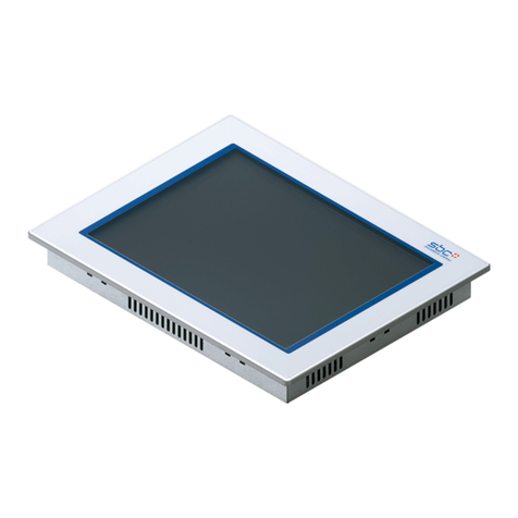
Digital Equipment Pro-face FP2500-T41 User manual

FP2500-T41
User Manual
Digital Electronics Corporation

FP2500-T41 User Manual i
1) It is forbidden to copy the contents of this manual, in whole or in part, except for
theuser'spersonaluse,withouttheexpresspermissionoftheDigitalElectronics
Corporation of Japan.
2) Theinformationprovidedinthismanualissubjecttochangewithoutnotice.
3) Thismanualhas been writtenwithcareandattention todetail;however,shouldyou
findanyerrorsoromissions,pleasecontactDigitalElectronicsandinformthemof
yourfindings.
4) Pleasebe awarethatDigital Electronicsis notresponsiblefor anydamages result-
ing from the use of our products, regardless of article 3 above.
5) Specificationsset out inthis manual are for overseas products only,and, as aresult,
somedifferencesmayexist betweenthespecficationsgiven hereandtheJapanese
ones.
AllCompany/Manufacturernamesusedin this manualaretheregisteredtrademarksof
theirrespectivecompanies.
© 2001,DigitalElectronics Corporation
<Note>
Preface
Thankyou forpurchasingDigital’sTFT typecolordisplay panel,the 'FP2500-T41'
(hereafter referred to as the FP unit).
TheFP unit isa TFTtype colorliquid crystal displaymonitor forIBM-PC compatible
personalcomputers(VGAmode).
Pleaseread thismanual completely to insure thecorrect useand completeunderstand-
ingofthe FPunit'sfunctions. The FP'sanalog interface isdesigned for usewith
standard VGA mode. Please be aware that this unit may not be able to be connected
with nonstandard VGA modes. For more details, please refer to this manual's "PC
ConnectivityNotes"section.
The term FP2500-T41 refers to the following unit:
FP2500-T41-24V (DC 24V type)

ii FP2500-T41 User Manual
Other Symbols Used In This Manual
The list below describes the symbols used in this manual.
Explains a situation that requires a moderate amount of caution.
Indicates a word or phrase that has an additional explanation.
A reference point. Describes the word or phrase marked by the as-
terisk (*) and the corresponding number.
Reference pages on related topics.
Thismanual describes safetyinstructions for correctuse of the FP unit. Please keep this
manual close at hand, and refer to it when necessary.
The following symbols are used throughout this manual to ensure the safe use of the FP
unit. Pleasemakesuretofollowallinstructionsgivensincetheyexplainimportantsafety
points.
For the Safe And Correct Use of this Unit:
*1
1),2) Operational steps. Please follow these numbered steps in order to
perform the desired operation.
This mark warns of a situation that could either seriously
injure a person or lead to death if the instruction is ignored
and/or the unit is used incorrectly.
This mark warns of a situation that could either injure a
person or damage property if the instruction is ignored and/
or the unit is used incorrectly.
Warning
Caution

FP2500-T41 User Manual iii
Safety Instructions
For the safe use of this unit, be sure to follow these guidelines:
Warning
Because of the ever present danger of electrical shock, be sure to unplug the power cable
fromtheFP unit beforepluggingthe cable's otherendinto thewall.
Donotusepower inexcessofthe unit's specifiedvoltagerangesince itmaycausea fireor
electricshock.
Because the FP unit contains high voltage parts, an electric shock can occur when disas-
semblingtheunit. Therefore,pleasebesuretoalwaysunplugtheunitbeforedisassembling
it.
Donot modify the FPunit in any way,since it maycause a fire or electric shock.
Whenchangingthebacklight,besuretoturnofftheunit'spowerfirst,inordertopreventan
electricshock.
Donotusetouchpanelkeystoperformlife-threateningorvitallyimportantsafetyfunctions.
Useseparate mechanical switchesfor suchkeys.
Ifsubstantialamountsofmetallicdust,waterorliquidsentertheFPunit,turnoffthepower
supplyimmediately, unplugthepowercord,andcontactyour local FPdistributor.
WheninstallingtheFPunit,besuretofollowtheinstructionsgivenin“Chapter3.Installation
andWiring,"toinsureitisdonecorrectly.
Donotusethe FP inanenvironmentwith flammablegassinceitmay causeanexplosion.

iv FP2500-T41 User Manual
Do not press the screen's touch surface too strongly with either your finger or a hard
object, since the touch surface may be damaged.
Whenthesurfaceofthedisplayscreenbecomesdirtyorsmudged,cleanthedisplay with
acloth soaked in a neutral detergent. Donot use paintthinner or organic solvent.
Donot presson the touchpanel's facewith sharpobjects, such asa mechanicalpencil or
screwdriver,since it might damagetheLCDpanel.
AvoidusingorstoringtheFPindirectsunlight,excessivelydustyordirtyenvironments,or
wherechemicals or their vaporsare present inthe air.
AvoidrestrictingtheFP'snaturalventilation,orstoringandusingtheFPinanenvironment
thatwillincreasetheFP'sinternaltemperature.
PleaseavoidusingtheFPinareaswheresudden,largechangesintemperaturemayoccur.
Thesechangescancausecondensationtoforminsidetheunit,possiblycausinganaccident.
TheFP'sLCDcontainsastrong irritant. If thepanelisevercrackedandthe LCD's liquid
contactsyourskin,be suretowashit withrunningwaterfor atleast15minutes. If anyof
thisliquidshouldenteryoureye,besuretoflushtheeyewithrunningwaterformorethan
15minutes, andsee adoctor immediately.
ThecurrentbrightnessoftheLCDscreenwilldependon the screen'scurrentdisplayand
theLCD'scontrastadjustment.Any brightness variationsthatresultarenormal for LCD
displays.
There are minute grid-points on the LCD surface. These points are not defects.
Sometimes crosstalk (shadows appearing on extended display lines) will appear on the
display. This phenomenon is a common attribute of LCD's and is not a defect.
Thedisplayedcolor will lookdifferentwhen viewedfroman angle outsidethespecified
viewangle.Thisisalsonormal.
Displaying a single screen image for long periods of time can cause an afterimage to
remain. To correct this, turn the unit OFF for 5 or 10 minutes, then ON again. This
phenomenonisacommonattributeoftheLCD's,andnotadefect. Topreventthiseffect,
youcan: - use the Display OFF feature, if the same image is to be displayed
for a long period of time.
-changethe screendisplayperiodically to preventthe displaying ofa
single image for along period oftime.
Safety Instructions
For the correct use of this unit, please follow these guidelines:
Notes on the FP's Liquid Crystal Display (LCD)
Caution


FP2500-T41 User Manual v
Table of Contents
Preface ........................................................................................................................i
For the Safe and Correct Use of this Unit..................................................................ii
Warning: Safety Instructions .......................................................................................iii
Caution: Safety Instructions ........................................................................................ iv
Table of Contents ........................................................................................................v
When Connecting to a PC...........................................................................................vii
FP2500-T41 Features..................................................................................................viii
Package Contents ....................................................................................................... ix
UL/c-UL (CSA) Application Notes ...........................................................................x
CE Making Notes........................................................................................................x
Chapter 1—Introduction
1-1 Connecting the FP to a PC .................................................................................. 1-1
1-2 Optional Equipment ...............................................................................................1-2
Chapter 2—Specifications
2-1 General Specifications (For DC24V) ................................................................... 2-1
1 Electrical Specifications ..............................................................................................2-1
2 Environmental Specifications .....................................................................................2-1
3 Structural Specifications.............................................................................................2-2
2-2 Functional Specifications (For DC24V) ..........................................................................2-3
2-3 Interface Specifications (For DC24V) ...........................................................................2-4
1 Analog RGB Interface .................................................................................................2-4
2 Serial Interface ............................................................................................................2-6
3 USB Interface ..............................................................................................................2-7
2-4 Cable Diagrams ...................................................................................................2-8
1 Pin Connections for the RGB Interface Cable............................................................2-8
2 Pin Connections for the SIO Interface Cable .............................................................2-9
3 Pin Connections for the USB Interface Cable ...........................................................2-9
2-5 Names and Functions of FP Parts.............................................................. 2-10
2-6 Flat Panel (FP) Dimensions........................................................................ 2-11
1 ExternalDimensions (DC24V) ............................................................................. 2-11
2 Installation Brackets ........................................................................................... 2-12
3 FP Installation Dimensions ................................................................................. 2-12

vi FP2500-T41 User Manual
Chapter 3—Installation and Wiring
3-1 Installation .................................................................................................................3-1
3-2 Wiring ........................................................................................................................3-5
1 Power Cable Connection ................................................................................................... 3-5
2 Precautions: Connecting the Power Supply...................................................................... 3-6
3 Precautions: Grounding .....................................................................................................3-7
4 Precautions: Input/Output Signal Lines............................................................................ 3-7
3-3 Operation Mode Setup and Display Positioning .......................................................3-8
1 Operation Mode Setup and Adjustment ..............................................................3-8
2 Front LED Option Mode Display .....................................................................................3-9
3 Display Position Compensation by OSD..........................................................................3-10
Chapter 4—Touch Panel Commands
4-1 Command List..........................................................................................................4-1
4-2 Boot-upInitialization ................................................................................................4-2
4-3 Touch Interface Data ..............................................................................................4-3
4-4 Touch Panel Commands..........................................................................................4-5
Chapter 5—Touch Panel Communication Programs
5-1 Bundled Software....................................................................................................5-1
5-2 Operation Environment............................................................................................5-2
5-3 Touch panel Input Drivers .......................................................................................5-3
1 FPATPH.EXE (Touch Panel Handler) ............................................................................... 5-3
2 FPCALIB.EXE (Touch Panel Data Calibration) ................................................................ 5-7
Chapter 6—Troubleshooting
6-1 Troubleshooting........................................................................................................6-1
1 Possible Device Problems ................................................................................................ 6-1
2 No Display ........................................................................................................................ 6-2
3 Touch Panel Does Not Work ............................................................................................ 6-4
Chapter 7—Maintenance
7-1 Regular Cleaning .....................................................................................................7-1
1 Cleaning the Display ........................................................................................................ 7-1
2 Installation Gasket Check/Replacement ........................................................................... 7-1
7-2 Periodic Check Points .............................................................................................7-2
7-3 Replacing the Backlight ...........................................................................................7-3
INDEX.............................................................................................i - iv

FP2500-T41 User Manual vii
• Changeover from horizontal 720 pixels to 640 pixels is done via DIP switch.
• When the horizontal 720 pixel signal is input;
- VGA Graphic & Text mode displays 640 pixels only and 80 pixels are not
displayed.
- VGA Graphic mode displays all pixels but images may be cut off if they do
not match the sampling.
• With vertical 350 pixels, 400 pixels, including 50 pixels at the top and at the
bottom of the screen will be enlarged and displayed at 480 pixels (1.2 times).
• When the unit is used in VGA text mode, the far right side's 80 dots are
not displayed.
• The display mode is designated using dip switch SW1-4.
SometypesofVGAequipmentmaynotbewithintherangesspecifiedabove,and,therefore,
cannot be connected to the FP.
Also, if the user changes his PC's VGA board, there is the possiblity that the new board
may not be able to be connected to the FP.
When Connecting to a PC
The FP unit's analog interface is designed for standard VGA mode. The number of dots
(pixels)displayedareasfollows:
Size H Sync. V Sync. Dot Clock Range
640X480 31.469±1KHz 60±1Hz 25.175MHz±1%
640X400 24.827±1KHz 56±1Hz 21.053MHz±1%
640X400 31.469±1KHz 70±1Hz 25.175MHz±1%
640X350 31.469±1KHz 70±1Hz 25.175MHz±1%
720X400 31.469±1KHz 70±1Hz 28.322MHz±1%
720X350 31.469±1KHz 70±1Hz 28.322MHz±1%

viii FP2500-T41 User Manual
High Quality TFT Color LCD Display
Thisunitis equippedwitha 10.4inchTFT typecolorLCD. Its superiorbrightnessand
wideviewingangle,notfoundinordinarylaptoptypeTFTLCD's,widensyourscopeof
applications.
Thescreen's maximum resolution is 640 x 480pixels, and candisplay 260,000 colors.
Easy Installation In User’s Cabinets and Panels
The FP2500-T41's slim, lightweight, and compact design make installation a snap. It
was designed specifically for use as your IA (Industrial Automation) or OA (Office
Automation)systemmonitor. Theflat,frontpanelprovidesprotectionequivalenttothe
rigorousIP65Fstandard,and,evenwithoutitsoptionalprotectivecover,thefrontpanel
ishighly resistant toboth wateranddust.
Panel can be used as a VGA Display
Since the FP2500-T41 is equipped with an analog RGB interface, it can be connected
to any PC with standard VGA mode. (The PC's clock frequency, however, must be
withinthestandardrange)
Easy to use Built In Touch Panel
TheFP2500-T41'sbuiltintouchpanelisstandardequipment,allowingtouchpaneldata
to be output to a host PC via input/output commands and an RS-232C cable and USB
cable.Thisisperfectforsystemsrequiringbothtouchpaneloperationanddatamonitoring.
FP2500-T41 Features
The features of the FP2500-T41 are as follows.

FP2500-T41 User Manual ix
The FP's packing box contains the items listed below. Please check to be sure each is
includedandis not damaged.
FP unit (FP2500-T41-24V)
FP2500/2600
User Manual(Contained in plastic case)
Installation Gasket (1)
Installation Brackets (4)
3.5 inch floppy disk
FP2500-T41/FP2600-T41
(ContainsTouchPanelprograms) Installation Guide (1)
Theseitemshaveallbeencarefullypackedwithspecialattentiontoproductquality.
However, should you find anything damaged or missing, please contact your local
distributor immediately for prompt service.
Package Contents
User Manual
Installation
Guide

xFP2500-T41 User Manual
The FP2500-T41-24V is a UL/c-UL (CSA) listed product. (UL file No.E182139)
This unit conforms as a product to the following standards:
UL508 IndustrialControlEquipment
UL1604ElectricalEquipmentforuseinClass1&2-Division2,orClass3Hazardous
Locations.
CAN/CSA-C22.2, No. 1010-1
MESUREMENT AND CONTROL EQUIPMENT
(Safetyrequirementsforelectricalequipmentformesurementandlaboratoryuse)
FP2500-T41-24V(UL Registration Model: 30B0003-01)
<Cautions>
UL/c-UL (CSA) Application Notes
The FP must be used as a built-in component of an end-use product.
Thisunitshouldbeinstalledinthe front faceofametalpanel.
Ifthisunit isinstalledso astocool itself naturally,be suretoinstall itina verticalpanel.
Also, be sure that the FP unit is mounted at least 100 mm away from any adjacent
structuresorequipment.Iftheserequirements arenotmet,theheatgeneratedby theFP
unit's internal components may cause the unit to fail to meet UL/c-UL standard
requirements.
UL1604Conditions of Acceptability andHandlingCautions:
1. Power, input and output (I/O) wiring must be in accordance with Class I,
Division 2 wiring methods-Article 501-4(b) of the National Electrical Code, NFPA
70 within the United States, and in accordance with Section 18-152 of the Canadian
ElectricalCode for unitsinstalled within Canada.
2. Suitable for use in Class I, Division 2, Groups A, B, C and D, Hazardous Locations.
3. WARNING:Explosionhazard-substitutionofcomponentsmayimpairsuitabilityfor
Class I, Division 2.
4. WARNING: Explosion hazard - when in hazardous locations, turn power OFF before
replacing or wiring modules.
5. WARNING: Explosion hazard - do not disconnect equipment unless power has been
switched OFF, or the area is known to be non-hazardous.
CE Marking Notes
The FP2500-T41 -24V is a CE marked product that conforms to EMC directives
EN55011 class A and EN61000-6-2.
*For detailed CE marking information, please contact your local FP distributor.

12345678901234567890123456789012
12345678901234567890123456789012
12345678901234567890123456789012
12345678901234567890123456789012
12345678901234567890123456789012
12345678901234567890123456789012
12345678901234567890123456789012
12345678901234567890123456789012
12345678901234567890123456789012
12345678901234567890123456789012
12345678901234567890123456789012
12345678901234567890123456789012
12345678901234567890123456789012
12345678901234567890123456789012
12345678901234567890123456789012
12345678901234567890123456789012
12345678901234567890123456789012
12345678901234567890123456789012
12345678901234567890123456789012
12345678901234567890123456789012
12345678901234567890123456789012
1-1 Connecting the FP to a PC
SIO Interface Cable (5m)
(FP61V-IS00-O)
(StraightCable:Dsub9-pinfemale)
AnalogRGBInterfaceCable
(FP-CV00<2.5m>,FP-CV01<5m>)
(VGAstandard:Dsub 15-pinmale)
1-1
FP2500-T41User Manual
The following diagram illustrates the connection between the FP unit and a PC.
Chapter 1
Introduction
1. Connecting the FP to a PC
2. Optional Equipment
FP2500-T41unit
13
2
23
1
B type
A type
PersonalComputer
(PC)
USBInterface Cable (5m)
(FP-US00)
(A-B type Cable)

Introduction
1-2 FP2500-T41User Manual
1-2 Optional Equipment
AlloptionalitemslistedbelowareproductsofDigitalElectronicsCorporation.
Model Description
SIO Cable FP61V-IS00-O
Serial interface cable (5m) used for touch
panel data transmission between the host
and the FP or command transmission to
the FP. This is a straight Dsub9 pin female
cable.
RGB Cable FP-CV00
FP-CV01
Analog RGB interface cable when image
signal is output to the FP from the host.
VGA specifications (Dsub15 pin male)
FP-CV00 (2.5m), FP-CV01 (5m)
USB Cable FP-US00
USB interface cable (5m) used for touch
panel data transmission between the host
and the FP or command transmission to
the FP.
A-B type cable.
Backlight
Bulbs GP577RT-BL00-MS Replacement Backlight bulbs .
Installation
Brackets GP070-AT01 Metal installation brackets for FP2500-T41
Rubber
Gasket GP-WP10-MS Replacement rubber gasket, used when
installing the FP. Same as the FP's
original gasket.
Cover
Sheet
(Hard type) PSL-DF00
Provides disposable screen protection from
dust and other elements. The touch panel
can be used with the Cover Sheet attached
(5 sheets / set)
Mouse
Emulator V2 PL-TD000 Mouse Emulator software for FP
Item
Interface
Maintenance
Parts
Optional
Parts
*Operationenvironment isWindows®95, WindowsNT®4.0,Windows®98,Windows®2000.
WhenyouusePL-TD000,hardwaresettingscannotbeautomaticallydetected.
As a result, select the FP unit's currently connected COM Port, and enter the
settingsgivenin theFPmanual fortheAllocated I/Oaddressand Interrupt.

123456789012345678901234567890121
123456789012345678901234567890121
123456789012345678901234567890121
123456789012345678901234567890121
123456789012345678901234567890121
123456789012345678901234567890121
123456789012345678901234567890121
123456789012345678901234567890121
123456789012345678901234567890121
123456789012345678901234567890121
123456789012345678901234567890121
123456789012345678901234567890121
123456789012345678901234567890121
123456789012345678901234567890121
123456789012345678901234567890121
123456789012345678901234567890121
123456789012345678901234567890121
123456789012345678901234567890121
123456789012345678901234567890121
123456789012345678901234567890121
123456789012345678901234567890121
Chapter 2
Specifications
1. General Specifications 4. Cable Diagrams
2. Functional Specifications 5. Names and Functions of FP Parts
3. Interface Specifications 6. Flat Panel (FP) Dimensions
FP2500-T41 User Manual
2-1-2 Environment Specifications
2-1
*1 (See the next page's note)
2-1 General Specifications (For DC24V)
2-1-1 Electrical Specifications
DC24V (FP2500-T41)
Operating Temperature 0oCto 50 oC
Storage Temperature -10oC to 60 oC
Humidity 30to85%RH(non-condensing)
Vibration Endurance 19.8m/s2-10to25Hz(X,Y,Zdirections-30minuteseach)
Noise Immunity Noisevoltage: 1000Vp-p
Pulselength:1µs
Rise time (rise/fall): 1 ns
Pollution Level Notimmuneto corrosivegas
Grounding Lessthan100Ω,oryourcountry'sapplicablestandard
Protection*1 EquivalenttoIP65f(JEM1030)
Rated Voltage DC24V
Rated Voltage Range DC19.2VtoDC28.8V
Power Consumption 50Worless
In-Rush Current 30Aorless
Voltage Endurance AC1000V20mAfor1minute
(betweenchargingandFGterminals)
Insulation Resistance 10MΩorhigheratDC500V
(betweenchargingandFGterminals)

FP2500-T41 User Manual
Specifications
2-2
2-1-3 Structural Specifications
The front face of the FP unit, installed in a solid panel, has been tested using
conditions equivalent to the standard shown in the specification . Even though
the FP unit’s level of resistance is equivalent to the standard, oils that should
have no effect on the FP can possibly harm the unit. This can occur in areas
where either vaporized oils are present, or where low viscosity cutting oils are
allowed to adhere to the unit for long periods of time. If the FP’s front face
protection sheet becomes peeled off, these conditions can lead to the ingress of
oil into the FP and separate protection measures are suggested. Also, if non-
approved oils are present, it may cause deformation or corrosion of the front
panel’s plastic cover. Therefore, prior to installing the FP be sure to confirm the
type of conditions that will be present in the FP’s operating environment.
If the installation gasket is used for a long period of time, or if the unit and its
gasket are removed from the panel, the original level of the protection cannot be
guaranteed. To maintain the original protection level, you need to replace the
installation gasket regularly.
*1 (Continued from previous page)
DC24V (FP2500-T41)
External Dimensions 317Wx243Hx58Dmm
Weight 3.5 kgorless
CoolingSystem Naturalaircirculation

FP2500-T41 User Manual
Specifications
2-3
2-2 Functional Specifications (For DC24 V )
Display Media TFT ActivematrixcolorLCD
Display Size 26cm (type 10.4) Opposite angle
Display Area (mm) 221.2W×158.4H
Resolution 640(H)×480(V)pixels(1pixel=R+G+Bpixel)
Display Colors 262,144 colors (R/G/B Sixbits each)
Brightness 240cd/m2(typ)*1
Dot Pitch (mm) 0.33H×0.33W
Resolution: 1024×1024
Method : Resistive Film (Analog)
Analog RGBInterface
SIO Interface(touch Interface)
USB Interface(touch Interface)
Backlightcan be changed.
Lifetime :50,000 hourswhen continuouslylit(*2)at25 oC.
VGAgraphic &Textmode
640X480,640X400,640X350 mode displayavailable.
720X400,720X350 mode are also available,however,
the 720X400,720X350 screenswill displayonlyat640 pixelsand the rightside’s
horizontal80 pixelsdo notdisplay.
VGAGraphic mode (DIPSW4 isON.)
640X480,640X400,640X350 mode displayavailable.
In thiscase,the resolution 720X400,720X350 displays ashorizontal 640 pixels,
butthe imagesmaybe cutiftheydo notmatch sampling.
However,allmodes400 linesand 350 linesare centerdisplayed.
With 350 pixels,400 pixels,including 50pixelsatthe top and bottom willbe
enlarged and displayed as 480 pixels(1.2 times).
Backlight
Touch Panel
Interfaces
Display Mode
*1 Thebrightness at central part of the screenwhen displaying allwhite.
*2 2.5 times decreased brightness may be the life span, but this value is only for
reference and not a guaranteed value.

FP2500-T41 User Manual
Specifications
2-4
2-3-1 Analog RGB Interface
2-3 Interface Specifications (For DC 24V)
Inputsignal type Analog RGB
Input signal characteristic Image signal: analog RGB
Synchronous signal: TTL level, negative true or
positive true
Scanning type: non-interlase
Setting by OSD (On Screen
Display) Contrast Adjustment
Sub Contrast Adjustment
Brightness Adjustment
Horizontal Display Position Adjustment
Vertical Display Position Adjustment
Horizontal Adjustment
Phase Adjustment
Dimmer Adjustment
Default Setting (All Clear Function)
Size H Sync. V Sync. Dot Clock Range
640X480 31.469±1KHz 60±1Hz 25.175MHz±1%
640X400 24.827±1KHz 56±1Hz 21.053MHz±1%
640X400 31.469±1KHz 70±1Hz 25.175MHz±1%
640X350 31.469±1KHz 70±1Hz 25.175MHz±1%
720X400 31.469±1KHz 70±1Hz 28.322MHz±1%
720X350 31.469±1KHz 70±1Hz 28.322MHz±1%
• Changeoverfrom horizontal720 pixelsto 640pixels is done via DIPswitch.
• Whenthehorizontal720pixelsignalisinput;
- VGA Graphic & Text mode displays 640 pixels only and 80 pixels are not
displayed.
- VGAGraphic mode displays all pixelsbut images maybe cutoff if theydo
notmatch the sampling .
• With vertical 350 pixels, 400 pixels including 50 pixels at the top and at the
bottomofthescreenwillbeenlargedanddisplayedat 480pixels(1.2times).
• In VGA Graphic & text mode, the far right side's 80 pixels do not
display.
• Selection of display mode is done via switch SW1-4.

FP2500-T41 User Manual
Specifications
2-5
Pin
No. Signal Name Condition Pin Location
1 Analog R R signal input
2 Analog G G signal input
3 Analog B B signal input
4 Reserved NC (spare for input)
5 Digital grounding Digital signal GND
6 Return R R signal GND
7 Return G G signal GND
8 Return B B signal GND
9 Reserved NC (spare for input)
10 Digital grounding Digital signal GND
11 Reserved NC (spare for input)
12 Reserved NC (spare for input)
13 H. SYNC Horizontal synchronous
signal input
14 V. SYNC Vertical synchronous
signal input
15 Reserved NC (spare for input)
Pin Assignments and Signal Names for Analog RGB
Connector: MiniDsub15 pintype
Connectorset screw:Inch type(4-40)
11
15
1
5

FP2500-T41 User Manual
Specifications
2-6
Pin
No. Signal
Name Condition Pin Location
1 CD Carrier Detect (FP->Host)
2 RD Receive Data (FP->Host)
3 SD Send Data (FP<-Host)
4 DTR Data Terminal Ready (FP<-Host)
5 GND Ground
6 DSR Data Set Ready (FP->Host)
7 RS Request to Send (FP<-Host)
8 CS Clear to Send (FP->Host)
9 NC No connection
Concerning Signal Names
Signalnames used forthe serialinterface onFPunits aredesigned tomatch
the pin order used on most PC serial interfaces, so that a straight cable can
be used to connect the two. Therefore, connect each pin's signal to the same
signalname on thePC side.
For example, pin #2 'RD' should be connected to the 'RD' input terminal on
the PC's connector.
Refer to section "2-4 Cable Diagrams" for each signal's direction.
2-3-2 Serial Interface
Pin Assignments and Signal Names for Serial Interface
Connector: Dsub9pinfemale
Connector set screw: Inch type (4-40)
Serial Interface
Baud rate: 9600 bps
Data length: 8 bits
Parity: none
Stop bit: 1
6
9
1
5

FP2500-T41 User Manual
Specifications
2-7
2-3-3 USB Interface
Pin Assignments and Signal Names for USB Interface
Communication Low speed Device
Connector: Btypeconnector
Pin
NO. Signal
Name Condition Pin Location
1 USB1-5V +5VIN
2 USBD1(-) USBdata(-)
3 USBD1(+) USBdata(+)
4 GND Ground
12
43
Table of contents
Other Digital Equipment Industrial Monitor manuals
Popular Industrial Monitor manuals by other brands

Siemens
Siemens INOX PRO SIMATIC IFP1900 Compact operating instructions

Bartec
Bartec Polaris Remote 15" user manual

Austin Hughes
Austin Hughes RP-F821 user manual

Eaton
Eaton Cutler-Hammer PanelMate ePro PS 7685T-12... Replacement Procedures

ESA
ESA XM7W7 installation manual

Element4
Element4 LCD8000-97C user manual

Delta Electronics
Delta Electronics Terminal Panels Series TP02G-AS1 instruction sheet

KERR
KERR AMSL6A100 Operation and maintenance manual

Hope Industrial Systems
Hope Industrial Systems HIS-RL15- ***D Series user manual

Hitachi
Hitachi P50X901/DW3D Service manual

Acnodes
Acnodes APW5130 user manual

Advantech
Advantech FPM-3060G Series user manual