C.P. Electronics EBR-4SC User manual
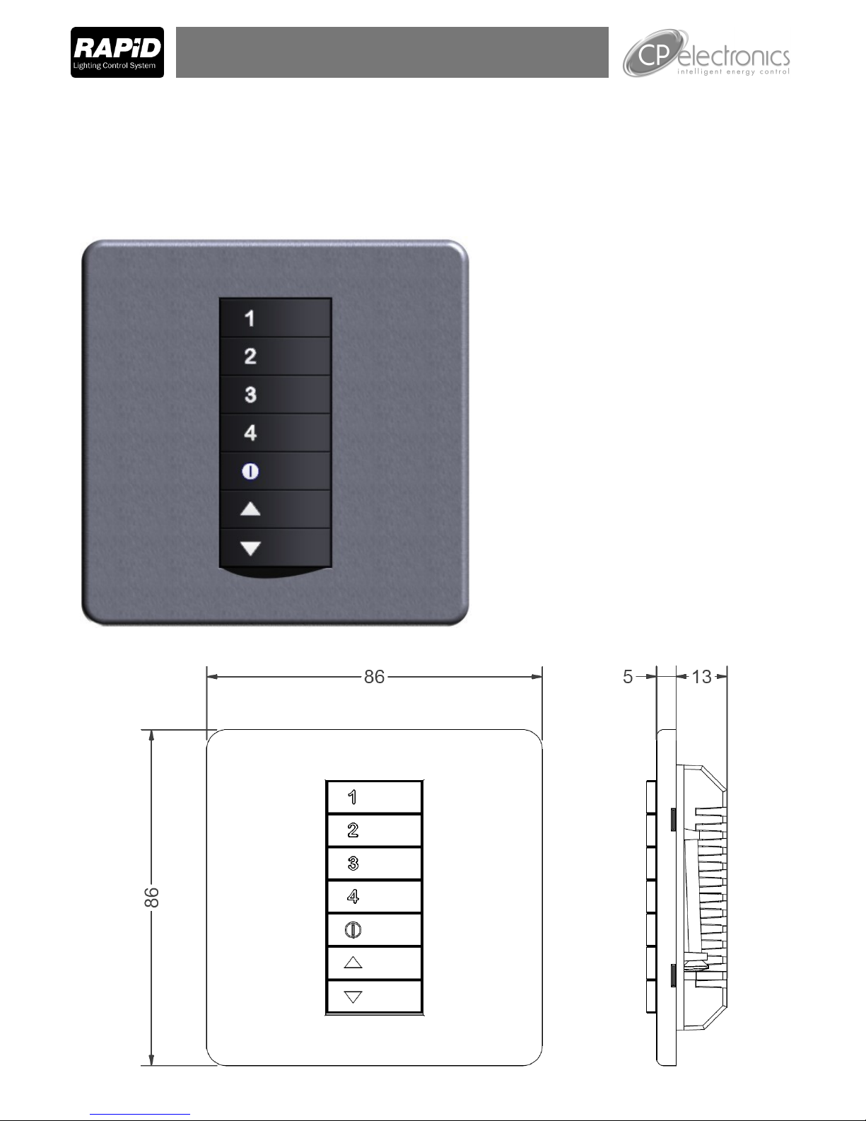
RAPID Scene Select Plate
Product Guide
EBR-4SC
Install the scene plate in a British standard flush box with a depth of at least 25mm.
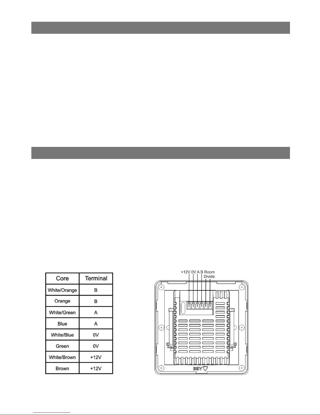
Wire the plate using a CAT5 cable with the one end stripped and wired as per the diagram below.
If required wire the room divide terminals to a switch (see Room Divide section)
Connect the other end of the CAT 5 cable via an RJ45 plug into port 3 or port 4 of the nearest LCM.
Screw the assembly to the wall and clip on the cover plate.
Commission using the notes overleaf.
Installation and Wiring
The EBR-4SC provides advanced scene setting functions for the Rapid Lighting Control System. When
used in conjunction with Rapid dimming LCMs and suitable dimming luminaires, complex dimming can
be achieved to suit applications from conference rooms to individual offices. This product provides for
the selection of scenes and the programming of LCMs to provide set dimming levels. The EBR-4SC
provides the following features:
Up to 8 scenes selectable using 4 buttons, plus a separate off scene
Up/down override
Adjustable fade rates up to 99 minutes, individually selectable for each scene
Room divide
Support for up to 99 individual dimming circuits
IR support for scene selection and programming
Keypad scene programming
Description and Operation

Operation
To select scenes 1-4, press the scene button. The LED in the button will illuminate.
To select scenes 5-8, press and hold the scene button for more than 1 second—the LED will flash.
The button assignments are:
scene 5 = button 1
scene 6 = button 2
scene 7 = button 3
scene 8 = button 4
When a new scene is selected, the desired light level be selected in the time determined by the fade
rate. Double clicking the button will override the fade rate and achieve this level immediately.
Scene 0 is reserved as the “off” scene, but can be programmed to leave a background lighting effect.

Commissioning will normally be performed by our trained commissioning engineers.
Please note that prior to commissioning, it is the responsibility of the installing contractor to ensure the
following:
The LCMs must be connected and installed
Mains power must be available
Luminaires must be plugged in
The scene plate must be wired correctly and plugged into the LCM
The LCMs are factory set to a preset scene level as follows:
Commissioning is performed using the LCD programming handset. The following relates to the com-
missioning of all scenes accessible by the plate.
1. Assign a Scene ID to the plate
2. Ensure that the required LCM channel has an interface dependency on the Scene ID
3. Program the Scene ID of the nearest plate to be the LCM master ID
4. Assign the LCM channel to a circuit and give it the circuit ID. A circuit is any group of luminaires
that need to have the same brightness level.
5. Select the scene on the scene plate. If it is scene 5-8, press and hold the button. If it is a room
divide scene, then ensure that the room divide contact is made.
6. From the scene menu of the handset, select the circuit ID to be programmed.
7. Adjust the brightness using the up/down buttons.
8. When completed, press the scene button to store the value.
9. Repeat above for all circuits and scenes.
10. Any other parameter, such as fade time can be directly programmed from the handset by se-
lecting the scene first and sending the command.
The scene values can also be programmed using the keys for all scenes and circuits 1-8. See the users
guide for details.
Scene Level
0 Off
1 100%
2 75%
3 50%
4 25%
5 50%
6 50%
7 50%
8 50%
Commissioning

Detectors and Interfaces
The scene plate can be used in conjunction with detectors, groups of detectors and clock interfaces to
select scenes. For example a presence detector can be used to select scene 1 when it detects, and
select scene 0 when the room is vacant.
To work in this mode dependencies on the relevant devices need to be entered on to the scene plate.
Note: dependencies should not be entered onto the LCM in this case. The LCM will only need to be
dependent on the scene plate, unless daylight linking is required.
Use the “Scene on” command to determine which scene is selected when an on message is received
from a detector, group or interface. In the case of a detector dependency, selected an on scene of 0 will
ignore the on message, so acting as an absence detector.
Use the “Scene off” command to determine which scene is selected when an off message is received.
Where a group dependency is added, a group off delay can be specified. The off scene will be selected
after the delay time, starting from when the last detector in the group was off.
Scene 1 can be used as a daylight linking scene. To achieve this the detector dependency should be
added to the LCM and the scene plate. When scene 1 is selected, daylight linking will occur. Any other
scene will disable this. This mode can be permanently disabled by removing the detector dependency
or disabled daylight linking on the LCM channel.

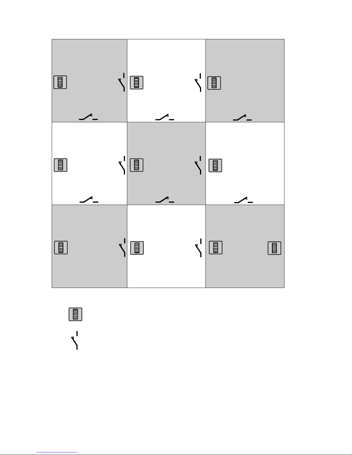
Room Divide
Any combination of connecting rooms can be automatically controlled using a combination of scene
plates and room divide switches.
Using the example overleaf:
All rooms will operate independently if the room divide switches are closed.
If, for example, switch 151 is opened between room 1 and 2, then the two scene plates will operate
together and the LCM will output the room divide scene.
Opening switch 153 will then cause rooms 1,2 and 3 to operate together.
To program this, follow the steps below:
1. Connect the room divide switches to the nearest LCM input—note the switches must be iso-
lated and must be closed when the room divide is closed.
2. Set the LCM interface ID and set the type to “Room divide”.
3. Add a dependency to the local LCM channels of the local scene plate ID. Only add the local
scene plate, do not add the ID for any adjacent rooms. Set the master ID to the local scene
plate.
4. Now each scene plate must be associated with scene plates in the adjacent rooms. To achieve
this, add dependencies to the scene plate: the adjacent scene plate ID and the adjacent room
divide ID. Repeat this for each adjacent room. For example, in the example opposite the fol-
lowing dependencies would be added to scene plate 101 (all interface dependencies) in this
exact order:
102, 151 (adds adjacent room 2)
104, 152 (adds adjacent room 4)
And for scene plate 102:
101, 151 (adds adjacent room 1)
103, 153 (adds adjacent room 3)
105, 154 (adds adjacent room 5)
This needs to be repeated for every room.
5. Note: when entering the dependencies, the room divide entry must immediately follow the
scene plate entry.
6. If an error is made in the entry, or the order is not followed exactly, simply repeat the entry of
the scene plate dependency and follow immediately with the room divide.
7. In a room where two scene plates are required to operate together (room 9 opposite), still only
one scene plate dependency should be entered on the LCM. The scene plates must be made
dependent on each other, using a dummy room interface ID of 999. So the entry for scene plate
109 would be:
108, 162 (adds adjacent room 8)
106, 160 (adds adjacent room 6)
110, 999 (adds same room second plate)
plate 110 would be:
109, 999 (adds same room first plate)
note: the adjacent rooms only need to be added to one plate in the room
Note: to retain backward compatibility, the room divide can still be attached to the scene plate using the
terminals provided. In this case a room divide dependency does not have to be added to the LCM,
however the LCM must be dependent on all secondary scene plates. The room divide switch in this
case must be open when the room divide is closed.
Room 1 Room 2 Room 3
Room 4 Room 5 Room 6
Room 7 Room 8 Room 9
ID
101
ID
151
ID
101
ID
201
Scene plate
Room divide switch
ID
152
ID
102
ID
153
ID
154
ID
103
ID
155
ID
104
ID
156
ID
157
ID
105
ID
158
ID
159
ID
106
ID
160
ID
107
ID
161
ID
108
ID
162
ID
109
ID
110

Ref: #WD242 Issue 2
LOAD
See datasheet for RAPID LCM
SUPPLY VOLTAGE 12VDC
TEMPERATURE -10°C to 35°C
CONFORMITY EMC-89/336/EEC
LVD-73/23/EEC
Specification
Part Numbers
EBR-4SC Eight scene, five button scene plate
C.P. Electronics Ltd
Brent Crescent
London
NW10 7XR
United Kingdom
Tel: + 44 (0) 333 900 0671
Fax: + 44 (0) 333 900 0674
www.cpelectronics.co.uk
IMPORTANT NOTICE!
This device should be installed by a qualified electrician in
accordance with the latest edition of the IEE wiring regulations.
Due to our policy of continual product improvement CP Electronics reserves the right
to alter the specification of this product without prior notice.
FM 45789 EMS 534520
Table of contents
Popular Lighting Equipment manuals by other brands


B-K lighting
B-K lighting Union Bollard installation instructions

LEF LIGHTING
LEF LIGHTING NEXTA RADIO TOUCH-LOCK4 manual

MaxLite
MaxLite HL-WP Series operating instructions

Titanium
Titanium TT-U-UX8 manual

American DJ
American DJ Electra 250 User instruction

numlighting
numlighting Dune Assembly instructions


