C.P. Electronics AT-BB-IN User manual
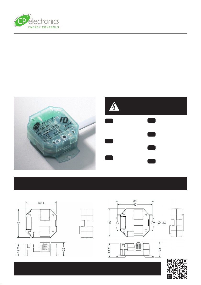
Dimensions (mm) | Abmessungen (mm) | Dimensiones (mm) | Dimensões (mm) | Dimensioni (mm) |
Dimensies (mm)
Warning | Warnung | Advertencia |
Aviso | Attention | Attenzione |
Waarschuwing
AT-BB-IN
Wireless, switch control interface
Kabellose, schaltergesteuerte Schnittstelle
Interfaz de control con conmutador, inalámbrico
Interface de controlo do interruptor sem os
Sans l, interface de commutateur de commande
Interfaccia di controllo interruttori wireless
Draadloze switch control-interface
EN This device should
be installed by a qualied
electrician in accordance with
the latest edition of the IEE
wiring regulations.
DE Dieses Gerät ist
ausschließlich von qualizierten
Elektrofachkräen zu
installieren.
ES Sólo un electricista
cualicado debe instalar este
dispositivo.
PT Somente um eletricista
qualicado deve instalar este
dispositivo.
FR Seul un électricien
qualié peut installer ce
dispositif.
IT Il dispositivo deve
essere installato da un
elettricista qualicato.
NL Dit apparaat moet
worden geïnstalleerd door een
gekwaliceerde elektricien.
Without bracket With bracket
WD371 Issue 5 Installation Guide
AT-BB-IN
Downloads and Videos | Downloads und Videos | Descargas y Videos | Descargas e Videos |
Téléchargements & Vidéos | Downloads e Video | Downloads en Video’s
cpelectronics.co.uk/cp/371
2
Installation | Instalación | instalação | Installazione | Installatie
EN The AT-BB-IN Input Unit can either
be mounted to any suitable solid surface or
concealed inside a backbox.
DE Die AT-BB-IN Eingabeeinheit kann
entweder auf einer geeigneten festen
Oberäche montiert oder in einer Backbox
verborgen werden.
ES La Unidad de entrada AT-BB-IN puede
montarse en cualquier supercie sólida
adecuada u ocultarse dentro de una caja de
conexiones.
PT A Unidade de Entrada AT-BB-I pode
ser montada em qualquer superfície sólida
adequada ou oculta no interior de uma
caixa traseira.
FR L’Unité d’entrée AT-BB-IN peut soit
être montée sur n’importe quelle surface
solide soit dissimulée à l’intérieur d’un
boîtier arrière.
IT L’unità AT-BB-IN può essere installata
su una supercie resistente idonea oppure
alloggiata all’interno di una backbox.
NL De AT-BB-IN-invoereenheid kan
worden gemonteerd op elk geschikt vast
oppervlak of verborgen in een inbouwdoos.
1
2
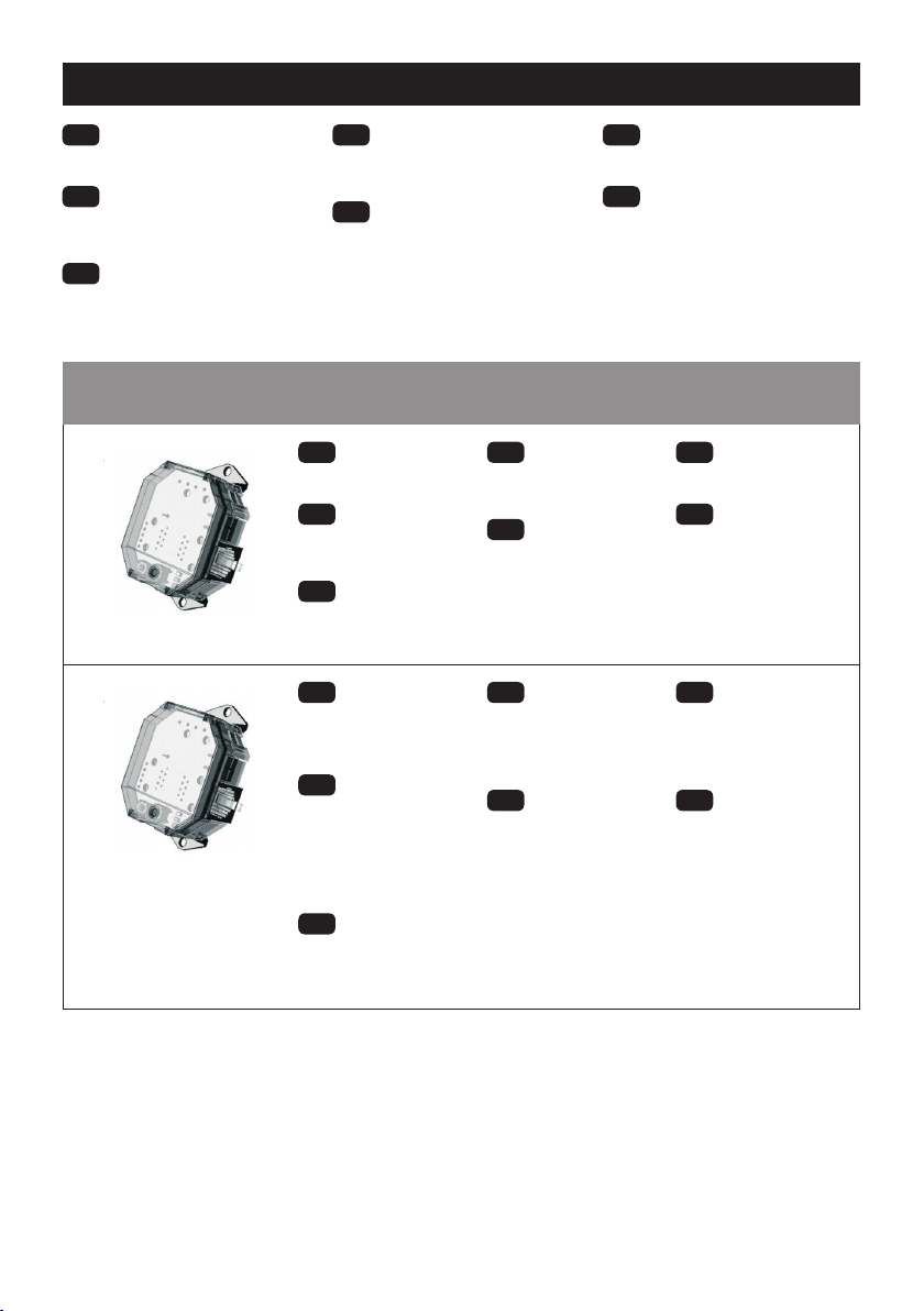
Surface mounting | Oberächenmontage | Montaje en supercie | Montagem de superfície |
Fixation en applique | Installazione su supercie | Montage
EN Fit the two snap-on
mounting brackets on the
back side of the unit.
DE Montieren Sie
die beiden Einschnapp-
Montagebügel auf der
Rückseite des Geräts.
ES Instale los dos
soportes de montaje de
retención en la parte trasera
de la unidad.
PT Ajuste os dois
suportes de montagem de
encaixe na parte traseira da
unidade.
FR Installez les deux
crochets de xation
encliquetables sur le côté
arrière de l’unité.
IT Posizionare i due
supporti di montaggio a
scatto sul retro dell’unità.
NL Bevestig
de twee opklikbare
bevestigingsbeugels aan de
achterzijde van de eenheid.
EN Use the holes in the
mounting brackets to ax
the unit to a wall or other solid
surface using suitable screw
xings.
DE Verwenden Sie
die Bohrungen in den
Montagebügeln, um das
Gerät mit geeigneten
Schraubbefestigungen
an einer Wand oder einer
anderen festen Oberäche zu
befestigen.
ES Utilice los oricios en
los soportes de montaje para
jar la unidad a una pared u
otra supercie sólida usando
tornillos adecuados.
PT Utilize os orifícios
nos suportes de montagem
para xar a unidade a uma
parede ou outra superfície
sólida, utilizando xações de
parafusos adequados.
FR Utilisez les trous des
crochets de montage pour
xer l’unité à un mur ou sur
une autre surface solide
au moyen de vis de xation
appropriées.
IT Utilizzare i fori nei
supporti di montaggio per
ssare l’unità a parete o su
una supercie resistente
utilizzando delle viti di
ssaggio adatte.
NL Gebruik de gaten in
de bevestigingsbeugels om
de eenheid op een wand
of ander vast oppervlak te
bevestigen met geschikte
schroeven.
2
Installation
The AT-BB-IN Input Unit can either be mounted to any
suitable solid surface or concealed inside a backbox.
Surface Mounting Method
Fit the two snap-on mounting brackets on the back side of
the unit as shown in opposite.
Use the holes in the mounting brackets to affix the unit to a
wall or other solid surface using suitable screw fixings.
Backbox Mounting Method
For unsecured fixing, the unit can be simply placed inside
a UK or European backbox (without fitting the snap-on
mounting brackets). This enables a proprietary switch
plate to be connected and screwed to the backbox.
Alternatively, for secured fixing, fit the two snap-on
mounting brackets on the front side of the unit as shown
opposite. The unit can then be secured to the backbox
using suitable fixing screws (up to M3.5).
NOTE: The mounting bracket holes are spaced to suit
either a UK (60.3mm pitch) or European (60mm pitch)
backbox.
CAUTION: Do not over tighten the fixing screws as
this may cause the brackets to split.
Mounting bracket location
for surface mounting.
Mounting bracket location for
secured backbox mounting.
Connections to the AT-BB-IN Input Unit are made via the
RJ45 lead supplied. The lead has 8 wires, comprising 7
switch inputs plus a common connection (see below).
Connect the lead wires to suitable push-buttons or switches
as required (see wiring examples on page 3).
Each input has two possible states:
Inactive when the input is unconnected
(i.e. open circuit), and
Active when the input is connected to common,
(i.e. during button or switch closure).
Each input can be configured (using the Switch Type
parameter) for use with either momentary or latching type
buttons and switches.
Momentary operation is the default, used for normally-
open push-buttons or centre-retractive type switches.
Latching operation is typically used for toggle type
switches that remain in either a closed or open state.
IMPORTANT NOTE: Latching Mode is not suited to battery
operation due to the continuous current drain while a switch
is closed. An external 12V power supply must, therefore,
Input connection identification
Electrical connection

3
Backbox mounting | Montage in Backbox | Método de montaje en caja de mecanismo | Método de montagem
da caixa traseira | Méthode de montage du boîtier arrière | Metodo di montaggio in una backbox |
Inbouwmethode
EN For unsecured xing, the unit can
be simply placed inside a UK or European
backbox (without tting the snap-on
mounting brackets). This enables a
proprietary switch plate to be connected
and screwed to the backbox. Alternatively,
for secured xing, t the two snap-on
mounting brackets on the front side of the
unit as shown opposite. The unit can then
be secured to the backbox using suitable
xing screws (up to M3.5).
NOTE: The mounting bracket holes are
spaced to suit either a UK (60.3mm pitch)
or European (60mm pitch) backbox.
CAUTION: Do not over tighten the xing
screws as this may cause the brackets
to split.
DE Für eine exible Montage kann
das Gerät einfach in einer britischen oder
europäischen Backbox platziert werden
(ohne die Einschnapp-Montagebügel).
So kann eine eigene Schalterplatte
angeschlossen und mit der Backbox
verschraubt werden. Alternativ können
Sie für eine dauerhae Befestigung
die beiden Einschnapp-Montagebügel
wie nebenstehend dargestellt an der
Vorderseite des Geräts anbringen.
Das Gerät kann dann mit geeigneten
Schrauben (max. M3,5) an der Backbox
befestigt werden.
HINWEIS: Die Bohrungen der
Montagebügel sind im passenden
Abstand für eine britische (60,3 mm)
oder eine europäische (60 mm) Backbox
angeordnet.
ACHTUNG: Ziehen Sie die
Befestigungsschrauben nicht zu fest an,
da dies zu einem Bruch der Montagebügel
führen kann.
ES Para una jación sin asegurar,
la unidad puede colocarse dentro
de una caja de conexiones de Reino
Unido o europea (sin instalar los
soportes de montaje de retención).
Esto permite conectar y atornillar una
placa conmutadora propia a la caja de
conexiones. Alternativamente, para una
jación segura, instale los dos soportes de
montaje de retención en el lado delantero
de la unidad, como se muestra. La unidad
puede jarse a la caja de conexiones
usando tornillos de jación adecuados
(hasta M3,5).
NOTA: Los oricios del soporte de
montaje están espaciados para adaptarse
a una caja de conexiones de Reino Unido
(inclinación de 60,3 mm) o europea
(inclinación de 60 mm).
PRECAUCIÓN: No apriete en exceso los
tornillos de jación ya que esto puede
causar que los soportes se rompan.
PT Para uma xação não segura, a
unidade pode ser simplesmente colocada
no interior de uma caixa traseira do
Reino Unido ou Europeia (sem ajustar os
suportes de montagem de encaixe). Isto
permite que uma placa de interruptor
patenteado seja ligada e aparafusada à
caixa traseira. Alternativamente, para uma
xação segura, ajuste os dois suportes
de montagem de encaixe na lateral da
unidade, conforme ilustrado do lado
oposto. A unidade pode ser xa à caixa
traseira utilizando parafusos de xação
adequados (até M3.5).
NOTA: Os orifícios do suporte de
montagem podem ser espaçados para
se adequar a uma caixa traseira do Reino
Unido (60,3 mm de passo) ou europeia
(60 mm de passo).
CUIDADO!: Não aperte demasiado os
parafusos de xação, visto que tal pode
resultar no ssuramento dos suportes.
FR Pour une xation peu sûre, l’unité
peut être simplement placée à l’intérieur
d’un boîtier du Royaume Uni ou de
l’Europe (sans les crochets de xation
encliquetables). Cette opération permet
la connexion et la xation d’une plaque
d’intérieure au boîtier arrière. Ou bien,
pour une xation sûre, installez les deux
crochets encliquetables sur le côté droit
de l’unité suivant l’illustration du côté
opposé. L’unité peut alors être sécurisée
sur le boîtier arrière au moyen des vis de
xation appropriées (jusqu’à M3,5).
NOTE : Les trous des crochets de xation
sont espacés de manière à convenir à un
boîtier arrière du Royaume Uni (pas de
60,3 mm) ou européen (pas de 60 mm).
AVERTISSEMENT : Do Ne serrez pas les
vis à l’extrême car cela risque d’entraîner la
rupture des crochets.
IT Se non si desidera ssare l’unità,
è possibile posizionarla all’interno di una
backbox per l’Europa o per il Regno Unito
(senza utilizzare i supporti di montaggio
a scatto). Questa soluzione consente di
collegare e ssare con viti una placca per
interruttori proprietaria alla backbox. In
alternativa, per ssare l’unità, posizionare
i due supporti di montaggio a scatto sulla
parte anteriore dell’unità come mostrato
nella pagina accanto. È possibile ssare
l’unità alla backbox utilizzando viti di
ssaggio apposite (no a M3.5).
NOTA: I fori dei supporti di montaggio
sono distanziati per consentire
l’installazione dell’unità in backbox per
il Regno Unito (passo 60,3 mm) o per
l’Europa (passo 60 mm).
ATTENZIONE: non serrare
eccessivamente le viti di ssaggio per non
danneggiare i supporti.
NL Op deze manier kan een
propriëtaire schakelplaat worden
aangesloten en op de inbouwdoos
worden geschroefd. Bevestig voor
montage met bevestiging de twee
opklikbare bevestigingsbeugels aan de
voorzijde van de eenheid zoals hiernaast
is aangegeven. De eenheid kan vervolgens
in de inbouwdoos worden bevestigd met
geschikte bouten (tot M3.5).
OPMERKING: De gaten in de
bevestigingsbeugels zodanig uit elkaar
geplaatst dat deze op een Britse (60,3
mm afstand) of Europese (60 mm
afstand) inbouwdoos passen.
WAARSCHUWING: Draai de bouten niet
te strak aan, omdat de beugels hierdoor
kunnen barsten.

4
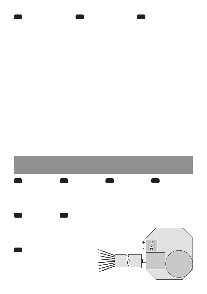
Electrical connection | Elektrischer Anschluss | Conexión eléctrica | Ligação elétrica | Raccordement
électrique | Collegamenti elettrici | Elektrische aansluiting
EN Connections to the AT-BB-IN Input
Unit are made via the RJ45 lead supplied. The
lead has 8 wires, comprising 7 switch inputs
plus a common connection (see below).
Connect the lead wires to suitable push-
buttons or switches as required (see wiring
examples on page 6).
Each input has two possible states:
• Inactive when the input is unconnected
(i.e. open circuit), and
• Active when the input is connected to
common,
(i.e. during button or switch closure).
Each input can be congured (using the
Switch Type parameter) for use with either
momentary or latching type buttons and
switches.
• Momentary operation is the default,
used for normally-open push-buttons or
centre-retractive type switches.
• Latching operation is typically used for
toggle type switches that remain in either
a closed or open state.
IMPORTANT NOTE: Latching Mode is
not suited to battery operation due to the
continuous current drain while a switch is
closed. An external 12V power supply must,
therefore, be wired in.
DE Der Anschluss der AT-BB-
IN Eingabeeinheit erfolgt mit dem
mitgelieferten RJ45-Kabel. Das Kabel
verfügt über 8 Drähte, bestehend aus 7
Signaleingängen und einem gemeinsamen
Anschluss (siehe unten).
Schließen Sie die Leitungen je nach Bedarf
an geeignete Taster oder Schalter an (siehe
Verdrahtungsbeispiele auf Seite 6).
Jeder Eingang hat zwei mögliche Zustände:
• Inaktiv, wenn der Eingang nicht
angeschlossen ist (d. h. oener
Schaltkreis), und
• Aktiv, wenn der Eingang mit Masse
verbunden ist, (z. B. beim Schließen von
Tasten oder Schaltern).
Jeder Eingang kann (unter Verwendung
des Parameters „Switch Type“) für die
Verwendung mit federnden oder rastenden
Tastern und Schaltern konguriert werden.
• Die Standardeinstellung ist die
Impulsbedienung, die für normal
geönete Drucktaster oder Wipptaster
verwendet wird.
• Der Verriegelungsmodus wird in der
Regel für Kippschalter verwendet, die
im geschlossenen oder im geöneten
Zustand verbleiben.
WICHTIGER HINWEIS: Der
Verriegelungsmodus ist aufgrund der
kontinuierlichen Stromaufnahme bei
geschlossenem Schalter nicht für den
Batteriebetrieb geeignet. Daher muss bei
Verwendung des Verriegelungsmodus
ein externes 12-V-Netzteil angeschlossen
werden.
ES Las conexiones a la unidad de entrada
AT-BB-IN se realizan mediante la conexión
RJ45. La conexión tiene 8 cables, que
comprenden 7 entradas del conmutador
además de una conexión común (ver a
continuación).
Conecte los cables de conexión a pulsadores
adecuados o conmutadores según sea
necesario (consulte los ejemplos de
cableado en la página 6).
Cada entrada tiene dos estados posibles:
• Inactiva cuando la entrada no está
conectada (es decir, circuito abierto), y
• Activa cuando la entrada está conectada
a común (es decir durante cierre de botón
o conmutador).
Cada entrada puede ser congurada
(usando el parámetro Tipo de conmutador)
para su uso con botones o conmutadores
temporales o de tipo pestillo).
• El funcionamiento temporal es el valor
predeterminado, usado para pulsadores
normalmente abiertos y conmutadores
de tipo retractivo central.
• La operación de pestillo se utiliza
normalmente para los conmutadores
de tipo alternar que permanecen en un
estado abierto o cerrado.
NOTA IMPORTANTE: El Modo de pestillo
no es adecuado para el funcionamiento
con batería debido al consumo continuo
de corriente mientras el conmutador está
cerrado. Debe usarse por tanto una fuente de
alimentación externa de 12V.
PT As ligações à Unidade de entrada AT-
BB-IN são efetuadas através do o condutor
RJ45 fornecido. O o condutor é composto
por 8 os que contam com 7 entradas de
interruptor e uma ligação comum (ver
abaixo).
Ligue os os condutores a botões adequados
ou interruptores conforme necessário (ver
exemplos de cablagem na pág. 6).
Cada entrada tem dois possíveis estados:
• Inativo quando a entrada está desligada
(ou seja, circuito aberto), e
• Ativo quando a entrada está ligada ao
comum, (ou seja, durante o encerramento
do botão ou interruptor).
Cada entrada pode ser congurada
(utilizando o parâmetro Tipo de interruptor)
para utilização com botões momentâneos
ou de trinco.
• A operação momentânea é a predenida,
utilizada para botões normalmente
abertos ou interruptores do tipo centro-
reativos.
• A operação de trinco é normalmente
utilizada para permutar interruptores
do tipo “toggle” que permanecem em
estado fechado ou aberto.
NOTA IMPORTANTE: O Modo de Trinco
não é adequado para a operação de bateria
devido à drenagem constante enquanto o
interruptor está fechado. Uma alimentação
de 12V externa deve, assim sendo.
5
Input connection identication | Identikation der Eingänge | Identicación de conexión de entrada |
Identicação da ligação de entrada | Identication de la borne d’entrée | Identicazione dei collegamenti agli
ingressi | Identicatie van ingangsverbindingen
EN Key
Switch 1 – Brown
Switch 2 – Blue
Switch 3 – Yellow
Switch 4 – Green
Switch 5 – Red
Switch 6 – Black
Switch 7 – Orange
Common (8) – Grey
DE Zeichenerklärung
Signal 1 – Braun
Signal 2 – Blau
Signal 3 – Gelb
Signal 4 – Grün
Signal 5 – Rot
Signal 6 – Schwarz
Signal 7 – Orange
Masse (8) – Grau
ES Leyenda
Conmutador 1 – Marrón
Conmutador 2 – Azul
Conmutador 3 – Amarillo
Conmutador 4 – Verde
Conmutador 5 – Rojo
Conmutador 6 – Negro
Conmutador 7 – Naranja
Común (8) – Gris
PT Legenda
Interruptor 1 – Castanho
Interruptor 2 – Azul
Interruptor 3 – Amarelo
Interruptor 4 – Verde
Interruptor 5 – Vermelho
Interruptor 6 – Preto
Interruptor 7 – Laranja
Comum (8) – Cinzento
FR Légende
Interrupteur 1 – Marron
Interrupteur 2 – Bleu
Interrupteur 3 – Jaune
Interrupteur 4 – Vert
Interrupteur 5 – Rouge
Interrupteur 6 – Noir
Interrupteur 7 – Orange
Commun (8) – Gris
IT Legenda
Interruttore 1 – Marrone
Interruttore 2 – Blu
Interruttore 3 – Giallo
Interruttore 4 – Verde
Interruttore 5 – Rosso
Interruttore 6 – Nero
Interruttore 7 – Arancione
Comune (8) – Grigio
NL Legenda
Schakelaar 1 – Bruin
Schakelaar 2 – Blauw
Schakelaar 3 – Geel
Schakelaar 4 – Groen
Schakelaar 5 – Rood
Schakelaar 6 – Zwart
Schakelaar 7 – Oranje
Algemeen (8) – Grijs
1
2
3
4
5
6
7
8
FR Les raccordements à l’Unité d’entrée
AT-BB-IN sont eectués au moyen du
plomb RJ45 fourni. Le plomb compte 8 ls
comprenant 7 entrées d’interrupteur plus un
raccordement commun (voir ci-dessous).
Connectez les ls de plomb aux boutons-
poussoirs ou aux interrupteurs suivant le cas
(voir des exemples de ls de branchement
à la page 6).
Chaque entrée a deux états possibles :
• Inactif lorsque l’entrée n’est pas
connectée (c’est-à-dire circuit ouvert), et
• Actif lorsque l’entrée est connectée
à commun, (c’est-à-dire pendant la
fermeture du bouton ou de l’interrupteur).
Il est possible de congurer chaque
entrée (au moyen du paramètre Type
d’interrupteur) pour utilisation avec
les boutons de type verrouillage ou
momentané et des interrupteurs.
• L’opération momentanée est
celle prévue par défaut, utilisée
normalement pour les boutons-
poussoirs normalement ouverts ou les
interrupteurs de type centre-rétractifs.
• L’opération de verrouillage est
habituellement utilisée pour les
interrupteurs de type bascule qui
restent dans un état fermé ou ouvert.
AVIS IMPORTANT : Le Mode verrouillage
n’est pas approprié au fonctionnement
de la batterie en raison du courant débité
en continu pendant que l’interrupteur est
fermé. Une fourniture de puissance 12V
doit, par conséquent.
IT I collegamenti all’unità AT-BB-IN
avvengono tramite il cavo RJ45 fornito in
dotazione. Il cavo presenta 8 derivazioni,
di cui 7 ingressi per interruttori e un
collegamento comune (vedere in basso).
Collegare le derivazioni ai pulsanti o agli
interruttori idonei secondo necessità
(vedere gli esempi di collegamento a
pagina 6).
Ciascun ingresso può essere:
• Inattivo, quando non è collegato (ovvero
circuito aperto)
• Attivo, quando è collegato al
collegamento comune (ovvero
durante la chiusura del pulsante o
dell’interruttore).
È possibile congurare ciascun ingresso
(servendosi del parametro del tipo di
interruttore) per utilizzare interruttori o
pulsanti di tipo bloccanti o momentanei.
• Il funzionamento momentaneo è
l’opzione predenita e viene utilizzata
per i pulsanti normalmente aperti o per
gli interruttori basculanti.
• Il funzionamento bloccante viene
utilizzato in genere per gli interruttori di
tipo attiva/disattiva che rimangono in
stato aperto o chiuso.
NOTA IMPORTANTE: la modalità
bloccante non è adatta al funzionamento
a batteria a causa della perdita continua
di corrente quando l’interruttore è chiuso.
In questo caso è necessario collegare un
alimentatore esterno da 12 V.
NL De aansluitingen op de AT-BB-
IN-invoereenheid worden gedaan met
behulp van de meegeleverde RJ45-kabel.
De kabel hee 8 draden, bestaande uit
7 schakelingangen en een algemene
aansluiting (zie hieronder).
Sluit de draden naar vereiste aan op
geschikte drukknoppen of schakelaars (zie
bedradingsvoorbeelden op pagina 6).
Elke ingang hee twee mogelijke statussen:
• Inactief wanneer de ingang niet is
verbonden (open circuit); en
• Actief wanneer de ingang is verbonden
met algemeen (bij sluiten van een knop
of schakelaar).
Elke ingang kan worden gecongureerd
(met behulp van de parameter
schakelaartype) voor gebruik met moment-
of vergrendelknoppen of -schakelaars.
• Momentwerking is standaard, wat
wordt gebruikt voor drukknoppen of
schakelaars met maakcontacten.
• Vergrendeling wordt gewoonlijk
gebruikt voor tuimelschakelaars die
geopend of gesloten blijven.
BELANGRIJK: De vergrendelingsmodus is
niet geschikt voor batterijvoeding vanwege
het voortdurende stroomverbruik wanneer
een schakelaar gesloten is. Er moet
daarom een externe 12 V voeding worden
gebruikt als de vergrendelingsmodus wordt
gebruikt.
6
Wiring | Verkabelung | Cableado | Ligações | Câblage | Cablaggio | Bedrading
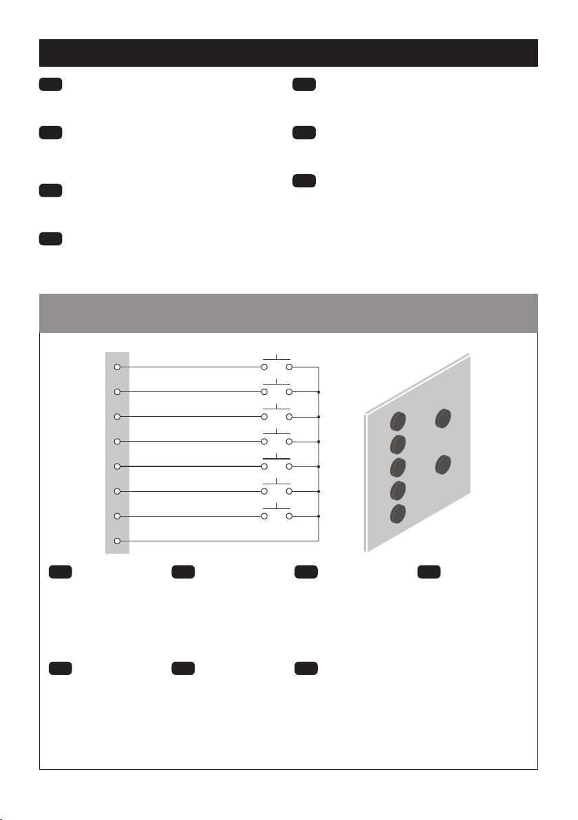
Individual push-buttons | Einzelnen Drucktasten | Pulsadores individuales | Botões individuais |
Boutons-poussoirs individuels | Singoli pulsanti | Afzonderlijke drukknoppen
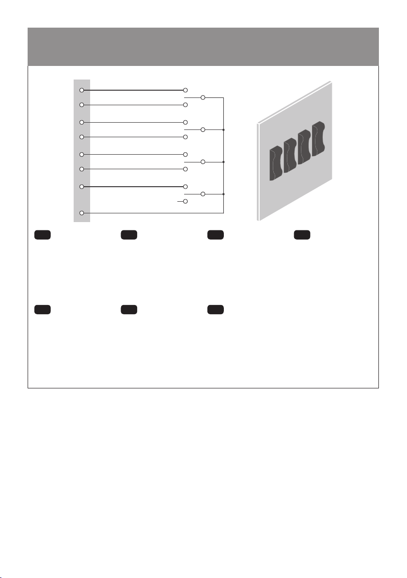
EN IMPORTANT NOTE: Latching modeis not suited to
battery operation due to the continuous current drain while a
switch is closed. An external 12V power supply must, therefore, be
connected if Latching Mode is used.
DE WICHTIGER HINWEIS: Der Verriegelungsmodus ist
aufgrund der kontinuierlichen Stromaufnahme bei geschlossenem
Schalter nicht für den Batteriebetrieb geeignet. Daher muss bei
Verwendung des Verriegelungsmodus ein externes 12-V-Netzteil
angeschlossen werden.
ES NOTA IMPORTANTE: El Modo de pestillo no es adecuado
para el funcionamiento con batería debido al consumo continuo
de corriente mientras el conmutador está cerrado. Debe usarse por
tanto una fuente de alimentación externa de 12V.
PT NOTA IMPORTANTE: O Modo de Trinco não é adequado
para a operação de bateria devido à drenagem constante enquanto
o interruptor está fechado. Uma alimentação de 12V externa deve,
assim sendo.
FR AVIS IMPORTANT : Le Mode verrouillage n’est pas
approprié au fonctionnement de la batterie en raison du courant
débité en continu pendant que l’interrupteur est fermé. Une
fourniture de puissance 12V doit, par conséquent.
IT NOTA IMPORTANTE: la modalità bloccante non è adatta al
funzionamento a batteria a causa della perdita continua di corrente
quando l’interruttore è chiuso. In questo caso è necessario
collegare un alimentatore esterno da 12 V.
NL BELANGRIJK: De vergrendelingsmodus is niet geschikt
voor batterijvoeding vanwege het voortdurende stroomverbruik
wanneer een schakelaar gesloten is. Er moet daarom een externe
12 V voeding worden gebruikt als de vergrendelingsmodus wordt
gebruikt.
EN Key
1. Input 1 – Brown
2. Input 2 – Blue
3. Input 3 – Yellow
4. Input 4 – Green
5. Input 5 – Red
6. Input 6 – Black
7. Input 7 – Orange
8. Common – Grey
DE Zeichenerklärung
1. Eingänge 1 – Braun
2. Eingänge 2 – Blau
3. Eingänge 3 – Gelb
4. Eingänge 4 – Grün
5. Eingänge 5 – Rot
6. Eingänge 6 – Schwarz
7. Eingänge 7 – Orange
8. Masse – Grau
ES Leyenda
1. Entrada 1 – Marrón
2. Entrada 2 – Azul
3. Entrada 3 – Amarillo
4. Entrada 4 – Verde
5. Entrada 5 – Rojo
6. Entrada 6 – Negro
7. Entrada 7 – Naranja
8. Común – Gris
PT Legenda
1. Entrada 1 – Castanho
2. Entrada 2 – Azul
3. Entrada 3 – Amarelo
4. Entrada 4 – Verde
5. Entrada 5 – Vermelho
6. Entrada 6 – Preto
7. Entrada 7 – Laranja
8. Comum – Cinzento
FR Légende
1. Entrée 1 – Marron
2. Entrée 2 – Bleu
3. Entrée 3 – Jaune
4. Entrée 4 – Vert
5. Entrée 5 – Rouge
6. Entrée 6 – Noir
7. Entrée 7 – Orange
8. Commun – Gris
IT Legenda
1. Ingressi 1 – Marrone
2. Ingressi 2 – Blu
3. Ingressi 3 – Giallo
4. Ingressi 4 – Verde
5. Ingressi 5 – Rosso
6. Ingressi 6 – Nero
7. Ingressi 7 – Arancione
8. Comune – Grigio
NL Legenda
1. Ingangs 1 – Bruin
2. Ingangs 2 – Blauw
3. Ingangs 3 – Geel
4. Ingangs 4 – Groen
5. Ingangs 5 – Rood
6. Ingangs 6 – Zwart
7. Ingangs 7 – Oranje
8. Algemeen – Grijs
1
2
3
4
5
6
7
8
7
Centre retractive switches | Einzugsschalter in der Mitte | Interruptores de retracción central |
Interruptores retractivos centrais | Interrupteurs centraux à rétraction | Interruttori retrattivi centrali |
Center retractieve schakelaars
EN Key
1. Input 1 – Brown
2. Input 2 – Blue
3. Input 3 – Yellow
4. Input 4 – Green
5. Input 5 – Red
6. Input 6 – Black
7. Input 7 – Orange
8. Common – Grey
9. Not connected
DE Zeichenerklärung
1. Eingänge 1 – Braun
2. Eingänge 2 – Blau
3. Eingänge 3 – Gelb
4. Eingänge 4 – Grün
5. Eingänge 5 – Rot
6. Eingänge 6 – Schwarz
7. Eingänge 7 – Orange
8. Masse – Grau
9. Nicht verbunden
ES Leyenda
1. Entrada 1 – Marrón
2. Entrada 2 – Azul
3. Entrada 3 – Amarillo
4. Entrada 4 – Verde
5. Entrada 5 – Rojo
6. Entrada 6 – Negro
7. Entrada 7 – Naranja
8. Común – Gris
9. No conectado
PT Legenda
1. Entrada 1 – Castanho
2. Entrada 2 – Azul
3. Entrada 3 – Amarelo
4. Entrada 4 – Verde
5. Entrada 5 – Vermelho
6. Entrada 6 – Preto
7. Entrada 7 – Laranja
8. Comum – Cinzento
9. Não conectado
FR Légende
1. Entrée 1 – Marron
2. Entrée 2 – Bleu
3. Entrée 3 – Jaune
4. Entrée 4 – Vert
5. Entrée 5 – Rouge
6. Entrée 6 – Noir
7. Entrée 7 – Orange
8. Commun – Gris
9. Pas connecté
IT Legenda
1. Ingressi 1 – Marrone
2. Ingressi 2 – Blu
3. Ingressi 3 – Giallo
4. Ingressi 4 – Verde
5. Ingressi 5 – Rosso
6. Ingressi 6 – Nero
7. Ingressi 7 – Arancione
8. Comune – Grigio
9. Non collegato
NL Legenda
1. Ingangs 1 – Bruin
2. Ingangs 2 – Blauw
3. Ingangs 3 – Geel
4. Ingangs 4 – Groen
5. Ingangs 5 – Rood
6. Ingangs 6 – Zwart
7. Ingangs 7 – Oranje
8. Algemeen – Grijs
9. Niet verbonden
1
2
3
4
5
6
7
8

8
Latching switches (for use with external 12Vdc supply only) | Verriegelungsschaltern (bei externer
12-V-Versorgung) | Conmutadores de pestillo (para su uso solo con fuente de alimentación de 12cd) |
Interruptores de trinco (apenas para utilização com uma alimentação de 12Vdc externa) | Interrupteurs de
verrouillage (uniquement pour utilisation avec une fourniture externe de 12V) | Teleruttori (solo per l’uso con
alimentatori esterni da 12 VCC) | Maakschakelaars (alleen voor gebruik met 12 VDC voeding)
EN Key
1. Input 1 – Brown
2. Input 2 – Blue
3. Input 3 – Yellow
4. Input 4 – Green
5. Input 5 – Red
6. Input 6 – Black
7. Input 7 – Orange
8. Common – Grey
DE Zeichenerklärung
1. Eingänge 1 – Braun
2. Eingänge 2 – Blau
3. Eingänge 3 – Gelb
4. Eingänge 4 – Grün
5. Eingänge 5 – Rot
6. Eingänge 6 – Schwarz
7. Eingänge 7 – Orange
8. Masse – Grau
ES Leyenda
1. Entrada 1 – Marrón
2. Entrada 2 – Azul
3. Entrada 3 – Amarillo
4. Entrada 4 – Verde
5. Entrada 5 – Rojo
6. Entrada 6 – Negro
7. Entrada 7 – Naranja
8. Común – Gris
PT Legenda
1. Entrada 1 – Castanho
2. Entrada 2 – Azul
3. Entrada 3 – Amarelo
4. Entrada 4 – Verde
5. Entrada 5 – Vermelho
6. Entrada 6 – Preto
7. Entrada 7 – Laranja
8. Comum – Cinzento
FR Légende
1. Entrée 1 – Marron
2. Entrée 2 – Bleu
3. Entrée 3 – Jaune
4. Entrée 4 – Vert
5. Entrée 5 – Rouge
6. Entrée 6 – Noir
7. Entrée 7 – Orange
8. Commun – Gris
IT Legenda
1. Ingressi 1 – Marrone
2. Ingressi 2 – Blu
3. Ingressi 3 – Giallo
4. Ingressi 4 – Verde
5. Ingressi 5 – Rosso
6. Ingressi 6 – Nero
7. Ingressi 7 – Arancione
8. Comune – Grigio
NL Legenda
1. Ingangs 1 – Bruin
2. Ingangs 2 – Blauw
3. Ingangs 3 – Geel
4. Ingangs 4 – Groen
5. Ingangs 5 – Rood
6. Ingangs 6 – Zwart
7. Ingangs 7 – Oranje
8. Algemeen – Grijs
1
2
3
4
5
6
7
8

9
Material (casing)
Humidity
Operational temp. ºC
Weight kg
Device
EN Technical Data
Flame retardant
polycarbonate
5 to 95% non-
condensing
0 to 35
0.025
AT-BB-IN
Material (Gehäuse)
Feuchtigkeit
Betriebstemperatur ºC
Gewicht kg
Device
DE Technische Daten
Flammwidriges
Polycarbonat
5 bis 95 % nicht
kondensierend
0 to 35
0.025
AT-BB-IN
Material (carcasa)
Humedad
°C de temperatura operativa
Peso (kg)
Dispositivo
ES Datos Técnicos
Policarbonato ignífugo
5-95% no
condensación
0 to 35
0.025
AT-BB-IN
Matériau (boîtier)
Humidité
Température de fonctionnement ºC
Poids (kg)
Device
FR Données Techniques
Polycarbonate ignifuge
5 à 95 % sans
condensation
0 to 35
0.025
AT-BB-IN
Materiale (rivestimento)
Umidità
Temperatura di esercizio ºC
Peso in kg
Dispositivo
IT Speciche Tecnichev
Policarbonato con
ritardante di fiamma
Da 5 a 95% senza
condensa
0 to 35
0.025
AT-BB-IN
Materiaal (behuizing)
Luchtvochtigheid
Operationele temperatuur (°C)
Gewicht kg
Apparaat
NL Technische data
Brandvertragend
polycarbonaat
5 tot 95%, niet
condenserend
0 to 35
0.025
AT-BB-IN
Material (caixa)
Umidade
Temperatura operacional (ºC)
Peso (kg)
Dispositivo
PT Dados Técnicos
Policarbonatos
retardantes de chamas
5 a 95% não
condensante
0 to 35
0.025
AT-BB-IN

10

11

12
WD371 Issue 5 Installation Guide, AT-BB-IN
18603
CP Electronics
A Business unit of Legrand Electric Limited,
Brent Crescent, London NW10 7XR, UK
t. +44 (0)333 900 0671
enquir[email protected]
www.cpelectronics.co.uk connect with us
Due to our policy of continual product improvement CP Electronics reserves the right to alter the specication of this product without prior notice.
Part Number | Artikelnummer |
Referencia | Referéncia | Référence |
Codice | Artikelnummer
Description | Beschreibung | Descripción | Descripção | Description |
Descrizione | Omschrijving
UNLCDHS
Universal LCD IR handset/commissioning handset | Fernbedienung und
Einstellwerkzeug | Mando profesional con pantalla LCD para programación y puesta en
marcha | Controle remoto LCD Universal | Outil universel de conguration / mise en
service avec écran LCD | Telecomando Universale LCD | Gevanceerde handset
Accessories & associated products | Zubehör | Accesorios y productos asociados | Acessórios e productos
associados | Accessoires et produits associés | Accessori e prodotti associati | Toebehoren
Other manuals for AT-BB-IN
1
Popular Recording Equipment manuals by other brands


Emerson
Emerson Bettis OM9-SCE300 Installation, operation and maintenance manual

Sony
Sony DEP-100 installation manual

TubeDepot
TubeDepot Tweed 5E3+ Assembly manual

Lutron Electronics
Lutron Electronics PAV6M-120 installation guide

Yamaha
Yamaha Midi XG MU90R Sound list

dbx
dbx DriveRack VENU360 owner's manual

Sony
Sony SRW5800/2 brochure

ALLEN & HEATH
ALLEN & HEATH AHM-16 Getting started guide

Murphy
Murphy CANdrive Module CDV100F Installation and operation manual

Yamaha
Yamaha QX-5FD owner's manual

Tema Telecomunicazioni
Tema Telecomunicazioni AA-11 Technical manual

Ingersoll-Rand
Ingersoll-Rand TRANE BCI-R Application guide