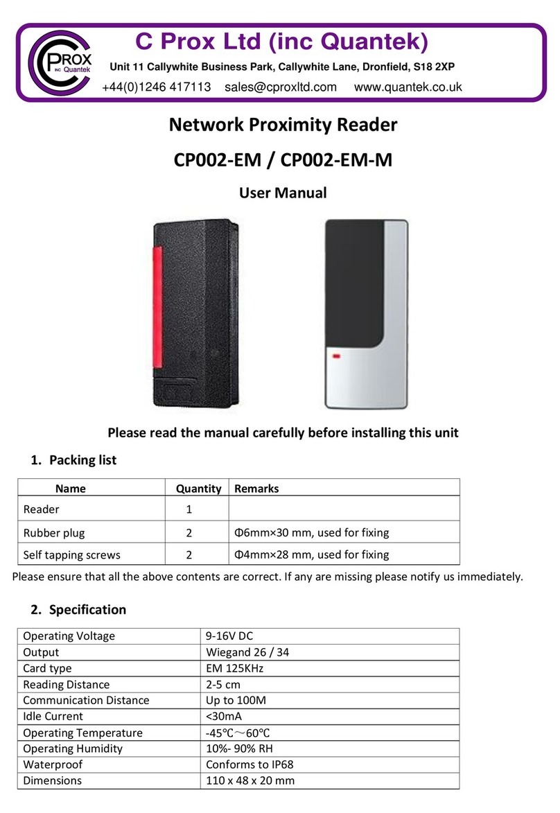
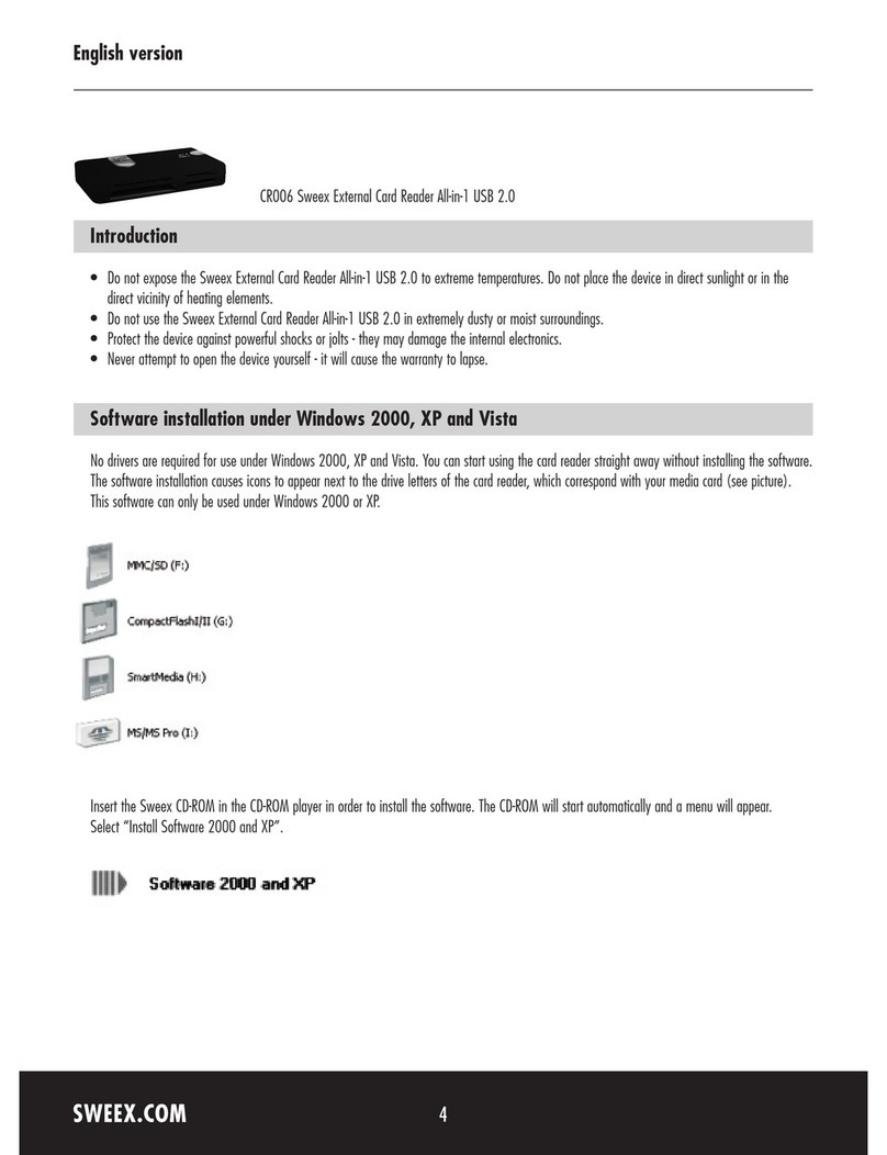
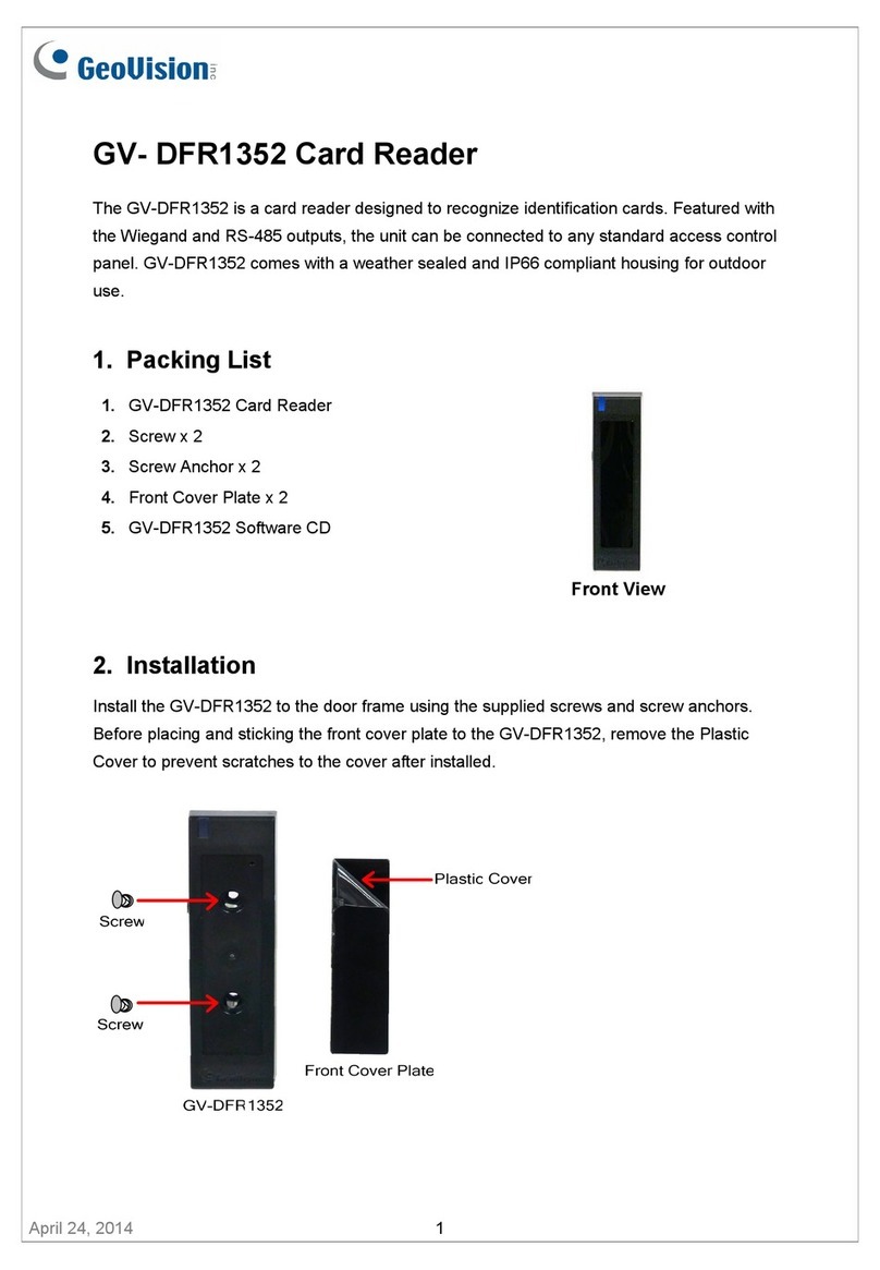
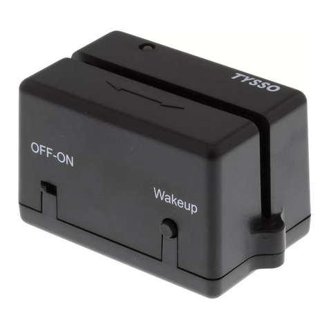
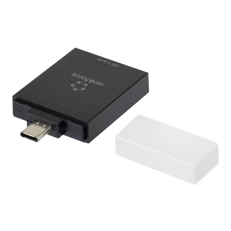
C Prox Quntek PN10 User manual

1
C Prox Ltd (inc Quantek)
Unit 11 Callywhite Business Park, Callywhite Lane, Dronfield, S18 2XP
Access Control Proximity Reader
PN10
User Manual
Please read the manual carefully before installing this unit

2
1. Packing list
Name
Quantity
Remarks
Proximity reader
1
PN10
Infrared remote
1
Admin add card
1
Admin delete card
1
User manual
1
Self-tapping screws
2
Φ3.5mm×27mm, used for fixing
Screw driver
1
Star
Please ensure that all the above contents are correct. If any are missing please notify us immediately
2. Description
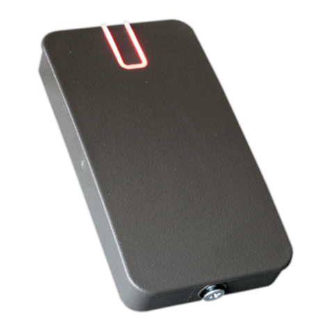
The PN10 is a waterproof standalone or Wiegand access control proximity reader. It uses an advanced
microprocessor with a high capacity flash memory for up to 10,000 users. Users can be added and deleted
via admin cards making it very simple to operate. The infrared remote control allows settings to be quickly
changed, including altering the relay time. It has low power consumption and door release button
connection, all these make it convenient, safe and reliable.
3. Features
•Zinc alloy, anti-vandal shell
•Waterproof, conforms to IP68
•Supplied with a 1 metre cable
•High capacity memory, 10,000 users
•Wiegand 26 output and Wiegand 26 input
•Besides standalone, it can connect to a controller as a slave reader
•Infrared remote control and manager cards for programming
•Red, yellow and green LEDs display the working status
•Adjustable door unlocking time
•Fast operating speed
4. Specification
Operating voltage
12-24Vdc
User capacity
10,000
Static consumption
<35mA
Operating consumption
<100mA
Card reading distance
3-5cm
Frequency
125KHz
Operating temperature
-35 to 60⁰C
Operating humidity
0% to 95%
Lock output load
1A
Waterproof
IP68
Dimensions
115 x 56 x 22 mm

3
5. Installation
•Remove back plate from the reader using security driver supplied, and use it (or the template) to
mark the two fixing holes and one cable hole.
•Drill the cable and fixing holes.
•Secure back plate to the wall using fixing screws provided.
•Thread cable through the hole and connect wires needed, wrap unused wires with insulating tape
to prevent short circuit.
•Fit the reader into the back plate and replace retaining screw.
6. Wiring
Colour
Function
Description
Green
D0
Wiegand input D0 (Wiegand output in reader mode)
White
D1
Wiegand input D1 (Wiegand output in reader mode)
Yellow
OPEN/BEEP
Exit button one end (Beeper input reader mode)
Red
12/24V +
12/24V + DC regulated power input
Black
GND
12/24V –DC regulated power input
Blue
NO
Relay normally open
Purple
COM
Relay common
Orange
NC
Relay normally closed
Standalone mode

4
Reader mode
7. Factory reset
Turn off power to the unit. Press and hold the exit button whilst powering the unit up. After hearing 2
beeps release the exit button. The admin code has now been reset to 999999, and factory default settings
are restored.
Note: User data will not be deleted when performing a factory reset.
8. Sound & light indication
Operation
LED indicator
Buzzer
Standby
Red
Operation successful
Green
One Long beep
Operation failed
Three short beeps
Admin card enter programming
Two short beeps
Admin card exit programming
One long beep
Press IR remote key
One short beep
Press * key
One long beep
On process of reading multi user cards
Red flashing slowly
Enter programming mode
Red flashing slowly
Enter setting status
Yellow
Door unlocked
Green
Buzzer alarm
Red flashing quickly
Alarming

5
9. Programming
9.1 Add and delete users by admin cards
It is highly advised to make a note of the User ID number and card number to allow for individual deletion of cards
in the future, see the last page.
Add users
Read admin add card Read 1st user card Read 2nd user card … Read admin add card
Note: The admin add card is used to add cards continuously and quickly. When you read the admin add card for the first time
you will hear 2 short beeps and the indicator light will turn yellow, this means you have entered programming mode. When you
read the admin add card the second time, you will hear one long beep and the indicator light will turn red, meaning you have
exited programming mode.
Delete users
Read admin delete card Read 1st user card Read 2nd user card … Read admin delete card
Note: The admin delete card is used to delete cards continuously and quickly. When you read the admin delete card for the first
time you will hear 2 short beeps and the indicator light will turn yellow, this means you have entered programming mode. When
you read the admin delete card the second time, you will hear one long beep and the indicator light will turn red, meaning you
have exited programming mode.
9.2 Add and delete users by remote control
To enter programming mode
*Admin code #
999999 is default admin code
To exit programming mode
*Must be pressed after completing programming
Note that to undertake the following programming the administrator must be logged in
To add a card user (Method 1)
User ID number is automatically generated.
1Read card #
Cards can be added continuously without exiting programming mode
To add a card user (Method 2)
In this method a user ID number is allocated to a
card. User ID number is any number between 1 &
10,000. Only one user ID number per card.
1User ID number #Read card #
Cards can be added continuously without exiting programming mode
To add a card user (Method 3)
In this method the card is added by the 8 or 10
digit card number printed on the card. User ID
number is auto generated.
1Card number #
Cards can be added continuously without exiting programming mode
To add a card user (Method 4)
In this method a user ID number is allocated to a
card number. Only one user ID number per card.
1User ID number #Card number #
Cards can be added continuously without exiting programming mode
To add sequential card numbers
7User ID number #First Card number #Card quantity #
To delete a card user by card
2Read card #
Cards can be deleted continuously without exiting programming mode
To delete a card user by user ID number
This option can be used when someone has lost
their card
2User ID number #
Cards can be deleted continuously without exiting programming mode
To delete a card user by card number
This option can be used when someone has lost
their card
2Card number #
Cards can be deleted continuously without exiting programming mode
To delete ALL users
20000 #

6
9.3 Admin settings
To enter programming mode
*Admin code #
999999 is default admin code
To exit programming mode
*Must be pressed after completing programming
Note that to undertake the following programming the administrator must be logged in
To change the admin code
0New code #New code #
The admin code is any 6 digits
To set admin add card
110001 #Read card
To set admin delete card
110002 #Read card
To delete admin add card
210001 #
To delete admin delete card
210002 #
To set the working mode
Standalone access control mode (default)
Reader mode
Set Wiegand bits output
311 #When a valid card is read, relay pulses for the time set in section 9.4
313 #If connecting to an access controller
3(26-58) #(Default 26 bits)
9.4 Advanced settings
To enter programming mode
*Admin code #
999999 is default master code
To exit programming mode
*Must be pressed after completing programming
Note that to undertake the following programming the administrator must be logged in
To set multi card access
Entry by single card (default)
Entry by multiple cards
30# (default)
32-10 #2-10 is the number of cards that must be read one after
another to gain access. Cards must be read within 5 seconds.
To set the relay pulse time
40-300 #0-300 is the time in seconds the relay switches for when a
valid card(s) is read. 0 equals 50mS
To set the relay to latching mode
312 #Readvalidcard,relayswitches.Readvalidcardagain,relayswitchesback
Device lockout and alarm settings
Normal mode (default)
Alarm mode
Locked out mode
80#No alarm or lockout (default mode)
81#The built-in buzzer will alarm if 5 consecutive invalid cards are read
82#Thedevicewillbelockedoutfor10minutesif5consecutiveinvalidcardsareread
To set alarm time
50-99 #0-99 is the alarm time in minutes (default = 0)
Light indicator setting
Disable red light indicator
Enable red light indicator (default)
83#Red LED indicator off in standby mode
84#Red LED indicator on in standby mode (default)
Buzzer setting
Disable buzzer
Enable buzzer (default)
85#No buzzer when card read
86#Buzzer sounds when card read (default)

7
10. User operation
To open the door:
Read valid card
To turn off alarm:
Read valid card or Enter admin code#
11. Issue record
It is highly advised to make a note of the User ID number and card number to allow for individual deletion in the
future. It is always best to keep a digital copy of the issue record, especially on installations with over 10 users.
Site
Door location
Card/fob number
User ID number
User name
Issue date
Table of contents
Other C Prox Card Reader manuals
