responsibility to verify whether the installation or use is carried out according to the instructions.
Please contact the manufacturer when in doubt.
Operator
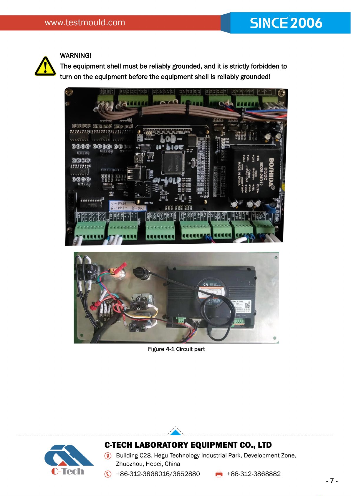
WARNING!
Only qualified personnel are allowed to use, transport, install, maintain,
dismantle and dispose of the equipment; this manual is specially written for
qualified operators and contains the necessary information for using the
equipment.
"Qualified operators" refer to personnel who have received training, conducted relevant tests, are
familiar with relevant standards, restrictions and measures, and are authorized by the factory safety
manager to identify and avoid any possible hazards.
The manufacturer recommends that users strictly follow the instructions, procedures,
recommendations and effective work safety regulations in this manual, and even use appropriate
protective equipment. Be familiar with and follow the instructions, safety warnings and hazards in
this manual in order to minimize the risks of installation, operation, management and maintenance.
Table 1: Responsibilities and Obligations of Factory Safety Managers
To know the functions, instructions, safety protection
devices, and possible dangers of the equipment, all the
detailed information in this manual, can be obtained
by carefully reading this manual.
Before using this equipment, proper training and
education should be carried out for "qualified
operators". Regarding equipment protect
careful training must be carried out.
In order to operate the equipment, it is necessary to
understand the current safety regulations in detail, and
to carry out transportation, handling, installation, use,
maintenance and disposal by qualified operators.
Ensure that the safety device of the equipment is not
damaged or disassembled, and check it every day.
Provide operators with appropriate personal protection
tools.
The manufacturer can explain and provide assistance and training for damages caused by improper use, errors
and negligence to people or persons caused by untrained personnel, but does not assume all responsibilities.
Warning and danger signs
This equipment is designed and manufactured according to current specifications, so it is equipped
with well-designed mechanical and electrical safety devices to protect operators or users from