GESTRA NRG 16-19 User manual

1
EN
English
Measuring electrode NRG 16-19
Measuring electrode NRG 16-27
Measuring electrode NRG 16-28
Test set VKE 16-1
Test set VKE 16 A
Test set VKE 26
NRG 16-19
NRG 16-27
NRG 16-28
VKE 16-1
VKE 16 A
VKE 26
Original Installation Instructions
818725-06

2
Usage for the intended purpose ..............................................................................................................4
Safety note .............................................................................................................................................4
PED (Pressure Equipment Directive)........................................................................................................5
ATEX (Atmosphère Explosible).................................................................................................................5
Note on the Declaration of Conformity / Declaration by the Manufacturer ..........................................5
Important Notes
Explanatory Notes
Scope of supply......................................................................................................................................5
Description .............................................................................................................................................6
Function .................................................................................................................................................6
Corrosion resistance...............................................................................................................................7
Sizing .....................................................................................................................................................7
NRG 16-19, NRG 16-27, NRG 16-28 .......................................................................................................7
Test chamber VKE 16-1, VKE 16-A ..........................................................................................................8
Test chamber VKE 26..............................................................................................................................8
Name plate / marking .............................................................................................................................9
Notice.....................................................................................................................................................9
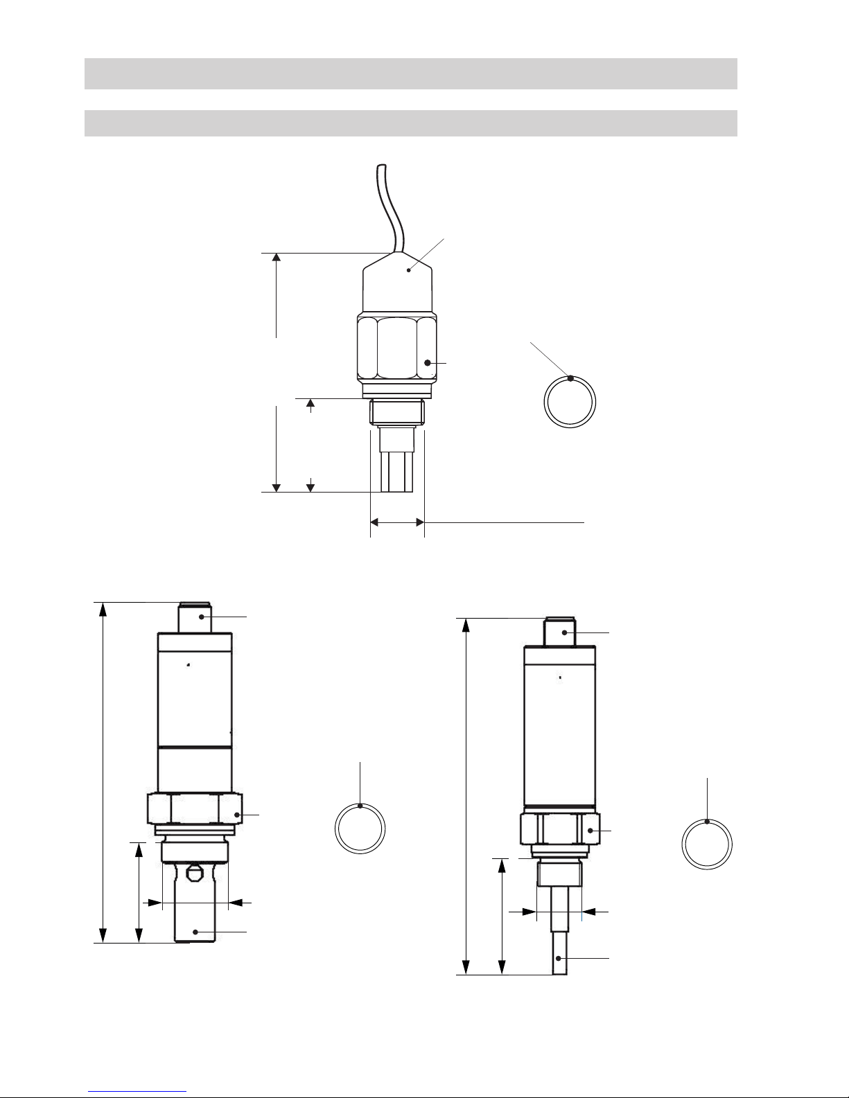
Dimensions of NRG 16-19, NRG 16-27, NRG 16-28 ..............................................................................10
Dimensions of test chamber VKE 16-1 .................................................................................................11
Dimensions of test chamber VKE 16 A ..................................................................................................12
Dimensions of test chamber VKE 26 .....................................................................................................13
Dimensions of NRG 16-28 for Rhombusline steam traps.......................................................................13
Technical Data
VKE 16-1, VKE 16-A, VKE 26 – Danger ..................................................................................................14
VKE 16-1, VKE 16-A..............................................................................................................................14
VKE 16-1, VKE 16 A Design with flanged ends.......................................................................................14
VKE 16-1 Design with screwed socket ends .........................................................................................14
VKE 16-1 Design with socket-weld ends...............................................................................................15
VKE 16-1 Design with butt-weld ends...................................................................................................15
Heat treatment of welds........................................................................................................................15
VKE 26..................................................................................................................................................15
NRG 16-19, NRG 16-27, NRG 16-28 .....................................................................................................16
Tools.....................................................................................................................................................16
Examples of installation NRG 16-19, NRG 16-27, NRG 16-28 ...............................................................17
Installation
Contents
Page

3
Wiring
Connecting cables for measuring electrodes.........................................................................................18
Wiring...................................................................................................................................................18
Tools.....................................................................................................................................................18
Measuring electrodes NRG 16-27, NRG 16-28 pin assignment..............................................................19
Commissioning
VKE 16-1, VKE 16-A, VKE 26 .................................................................................................................20
NRG 16-19, NRG 16-27, NRG 16-28 .....................................................................................................20
Applying mains voltage.........................................................................................................................20
Maintenance, removal and decommissioning
Maintenance interval ............................................................................................................................20
Removing and disposing of measuring electrode NRG 16-19, NRG 16-27 and NRG 16-2 ......................21
Contents – continued –
Page

4
Important Notes
Usage for the intended purpose
Use the electrodes NRG 16-19, NRG 16-27, NRG 16-28 and the test chambers VKE 16-1, VKE 16 A and
VKE 26 in conjunction with a suitable detector (e. g. test station NRA 1-3) only for monitoring steam
traps for banking-up of condensate and loss of live steam.
Danger
The measuring electrode, the test chamber and the steam trap are under pressure during
operation.
When loosening the measuring electrode, flanged connections and sealing plugs steam
or hot water might escape.
This presents the danger of severe scalds to the whole body.
Installation and maintenance work should only be carried out when the system is
depressurized (0 bar).
The equipment must be isolated and vented from both upstream and downstream
pressure.
The measuring electrode, test chamber and steam trap become hot during operation.
Touching the hot equipment presents the risk of severe burns to hands and arms.
Installation and maintenance work should only be carried out when the system is cold.
Before servicing the equipment or undoing flanged connections or sealing plugs make
sure that all connected lines are depressurized (0 bar) and cooled down to room tempe-
rature (20 °C).
Sharp edges on internal parts present the danger of cuts to hands.
Always wear industrial gloves when removing the strainer (steam trap).
Safety note
The equipment must only be installed and commissioned by qualified and competent staff.
Retrofitting and maintenance work must only be performed by qualified personnel who – through
adequate training – have achieved a recognised level of competence.
Attention
The name plate specifies the technical features of the equipment. Note that any piece of
equipment without its specific name plate must neither be commissioned nor operated.

5
Explanatory Notes
Scope of supply
NRG 16-19
1 Measuring electrode NRG 16-19
1 Joint ring D 17 x 21 to DIN 7603 (made from 1.4301), form D, bright annealed
1 Installation manual
NRG 16-27
1 Measuring electrode NRG 16-27
1 Joint ring D 17 x 21 to DIN 7603 (made from 1.4301), form D, bright annealed
1 Installation manual
NRG 16-28
1 Measuring electrode NRG 16-28
1 Joint ring D 24 x 29 to DIN 7603 (made from 1.4301), form D, bright annealed
1 Installation manual
VKE 16-1
1 Test chamber VKE 16-1
1 Installation manual
VKE 16 A
1 Test chamber VKE 16 A
1 Installation manual
VKE 26
1 Test chamber VKE 26
1 Installation manual
PED (Pressure Equipment Directive)
The equipment fulfils the requirements of the Pressure Equipment Directive (PED).
Applicable with fluids of group 2.
With CE marking (except for equipment according to section 4.3 of the PED).
ATEX (Atmosphère Explosible)
According to the European Directive the equipment must not be used in explosion-risk areas.
Important Notes – continued –
Note on the Declaration of Conformity / Declaration by the Manufacturer
For details on the conformity of our equipment according to the European Directives see our
Declaration of Conformity or our Declaration of Manufacturer.
The current Declaration of Conformity / Declaration of Manufacturer are available in the Internet under
www.gestra.com/documents or can be requested from us.

6
Explanatory Notes – continued –
Function
The following electrodes can be used for monitoring steam traps:
nMeasuring electrodes NRG 16-27, NRG 16-28 for detecting loss of live steam (electrode exposed)
and banking-up of condensate (by measuring the temperature of the condensate) or
nMeasuring electrode NRG 16-19 for detecting banking-up of condensate or loss of live steam
(electrode exposed or immerged).
The measuring electrode NRG 16-27, NRG 16-28 works according to the conductivity measurement
principle and detects steam loss (electrode exposed). The equipment is also equipped with a tempe-
rature sensing element PT 1000 for measuring the temperature of the condensate. The measuring
electrode is either screwed into the steam trap to be monitored or in the separate test chamber VKE
16-1 or VKE 16 A mounted upstream of the steam trap.
The measuring electrode NRG 16-19 works according to the conductivity measurement principle, too.
Depending on the installation the electrode detects either loss of live steam or banking-up of conden-
sate, see Fig. 11 (top). The measuring electrode is screwed into the test chamber VKE 16-1, VKE 16 A
(steam loss) or into the test chamber VKE 26 (banking-up of condensate).
The test chamber VKE 16-1, VKE 16 A can be installed upstream of any type or make of steam trap.
With float traps the test chamber VKE 26 is screwed on top into the vent hole. The air balance pipe is
connected to the test chamber.
The test station NRA 1-3 evaluates the signals coming from the measuring electrodes and indicates
banking-up of condensate, steam loss and malfunctions. The level switch NRS 1-2 can also be
connected to the measuring electrode NRG 16-19.
Description
A faulty steam trap can cause banking-up of condensate or steam loss.
The measuring electrode, which is screwed into the steam trap or a test chamber, detects malfunc-
tions in traps.
The test station NRA 1-3 evaluates the signals coming from the measuring electrodes and is designed
for the connection of up to max. 16 measuring electrodes.

7
NRG 16-19, NRG 16-27, NRG 16-28
Service pressure
PN 40, max. 32 barg at 238°C
Connection
NRG 16-19, NRG 16-27: screwed 3/8" to A ISO 228
NRG 16-28: screwed M 24 x 1.5
Materials
NRG 16-19
Screw-in body: 1.4301
Spacer disk: 1.4571
Electrode rod: 1.4571
Insulating disk: Gylon®
NRG 16-27, NRG 16-28
Screw-in body: 1.4571
Electrode rod: 1.4571
Insulation of electrode rod: PEEK
Sensitivity of response
> 1 μS/cm at 25°C
Electrode voltage
12 V
Electrical connection
NRG 16-19: Connecting line made from PTFE, 2 m long, 2 x 1.5 mm2
NRG 16-27, NRG 16-28: M 12 sensor connector, 5 poles, A coded
Protection
NRG 16-27, NRG 16-28: IP 65 to DIN EN 60529
NRG 16-19: IP 52 to DIN EN 60529
Ambient temperature at terminal box
Max. 80°C
Weight
Approx. 0.3 kg
Technical Data
Gylon®is a registered trademark of Garlock GmbH, Neuss
Corrosion resistance
When used for its intended purpose the safe functioning of the electrode will not be impaired by
corrosion.
Sizing
The body is not designed for pulsating loads. Dimensional allowances and anti-corrosive additives are
in accordance with the latest state-of-the-art.

8
Technical Data – continued –
Test chamber VKE 16-1, VKE 16 A
Designs
Electrode connection in flow direction to the left or to the right. Please state when ordering.
Pressure / temperature ratings
Service pressure barg 40 28.4 23.3 23.1
Related temperature °C 20 250 385 400
Materials VKE 16-1
Enclosure 1.0619
Flanges 1.0460
Connections
Flanges: DIN, PN 40
Screwed sockets: R and NPT thread
Nominal sizes: DN 15, 20, 25, ½", ¾", 1"
Available on request: DN 40, 50; 1½", 2"
Connection of electrode
Screwed 3/8" to ISO 228-1
Materials VKE 16 A
Enclosure 1.4571
Flanges 1.4571
Connections
Flanges: DIN, PN 40
Screwed sockets: R and NPT thread
Nominal sizes: DN 15, 20, 25, ½", ¾", 1"
Available on request: DN 40, 50; 1½", 2"
Connection of electrode
Screwed 3/8" to ISO 228-1
Test chamber VKE 26
Pressure / temperature ratings
Service pressure barg 40 28.4 23.3 23.1
Related temperature °C 20 250 385 400
Materials
Flanges 1.0460
Connections
Threaded standpipe: 3/8" BSP
Air-balance pipe: 3/8" BSP
Connection of electrode
Screwed 3/8" to ISO 228-1

9
Technical Data – continued –
Name plate / marking
Fig. 1 Equipment designation on hexagon part of electrode
Fig. 2 Name plate of NRG 16-27, NRG 16-28
Equipment designation
Manufacturer
Specification of
end connection
Protection
Equipment designation
Manufacturer
Specification of
end connection
Protection
Fig. 3 Name plate of test station
Notice
The body of test chamber VKE 16 A bears the stamp:
equipment number,
PN = 30 bar,
TN = 230 °C.

10
53.ac
621.ac
M24 x 1,5
Anschlussstecker
Messrohr
SW 30
Dichtring
ca. 45
ca. 137
G3/8, ISO 228-1
Anschlussstecker
Elektrodenstab
SW 27
Dichtring
Fig. 6 NRG 16-27
Technical Data – continued –
Dimensions of NRG 16-19, NRG 16-27, NRG 16-28
Fig. 5 NRG 16-19
Connector
3/8" to ISO 228-1
Joint ring
22 mm
A. F.
approx. 32
NRG 16-28
Connector
3/8" to ISO 228-1
Joint ring
30 mm
A. F.
approx. 126
approx. 35
Electrode tube
Measuring tube
approx. 80
approx. 45
approx. 137
27 mm
A.F.
Joint ring
Connector
M24 x 1.5

11
Technical Data – continued –
Dimensions of test chamber VKE 16-1
Dimensions Designs
Flanged to DIN Screwed sockets
Nominal size [mm] 15 20 25 40 50 15 20 25 40 50
[inch] ½ ¾ 1 1½ 2 ½ ¾ 1 1½ 2
Length
L 150 150 160
on request
95
on request
A~80 (NRG 16-19)
~130 (NRG 16-27)
~80 (NRG 16-19)
~130 (NRG 16-27)
Space required
for servicing S~40 (NRG 16-19)
~50 (NRG 16-27)
~40 (NRG 16-19)
~50 (NRG 16-27)
Height H1~93 ~93
H2~118 ~118
Fig. 7
L A S
H1
H2
Horizontal installation
(left) right

12
Technical Data – continued –
Dimensions of test chamber VKE 16 A
Dimensions Designs
Flanged to DIN
Nominal size [mm] 15 20 25 40 50
[inch] ½ ¾ 1 1½ 2
Length
L 160 160 160 200 230
A~90 (NRG 16-19)
~130 (NRG 16-27)
~100
~150
Space required
for servicing S~40 (NRG 16-19)
~50 (NRG 16-27)
Height H1~90 ~115
H2~143 ~186
Fig. 8
LA S
H1
H2

13
Technical Data – continued –
Dimensions of test chamber VKE 26
Fig. 9
Dimensions of NRG 16-28 for Rhombusline steam traps
Fig. 10
Electrode NRG 16-28
50 mm
Space required
for servicing
4072
27
84
37
10
2
70

14
Installation
VKE 16-1, VKE 16 A, VKE 26
VKE 16-1, VKE 16 A
Install test chamber only in horizontal pipes, see Fig. 7 and Fig. 8.
Risk of death, severe injuries, damage or destruction caused by the explosion of explosive
mixtures!
An electrically insulated installation between pipe flanges may result in electrostatic
charges.
If the equipment is used in explosion-risk areas make sure that any electrostatic charges
that may be generated will be discharged (earthing).
Danger
VKE 16-1, VKE 16 A Design with flanged ends
1. Observe correct position of installation.
2. Observe direction of flow. The flow arrow is on the trap body.
3. Consider space required for servicing. When the test chamber is installed a minimum space is
required for removing the measuring electrode (see table for Fig. 7 and Fig. 8).
4. Remove plastic plugs. They are only used as transit protection.
5. Clean seating surfaces of both flanges.
6. Install steam trap.
VKE 16-1 Design with screwed socket ends
1. Observe correct position of installation.
2. Observe direction of flow. The flow arrow is on the trap body.
3. Consider space required for servicing. When the test chamber is installed a minimum space is
required for removing the measuring electrode (see table for Fig. 7 and Fig. 8).
4. Remove plastic plugs. They are only used as transit protection.
5. Clean thread of screwed sockets.
6. Install steam trap.

15
Installation – continued –
VKE 16-1 Design with socket-weld ends
1. Observe correct position of installation.
2. Observe direction of flow. The flow arrow is on the trap body.
3. Consider space required for servicing. When the test chamber is installed a minimum space is
required for removing the measuring electrode (see table for Fig. 7 and Fig. 8).
4. Remove plastic plugs. They are only used as transit protection.
5. Clean socket-weld ends.
6. Apply arc welding processes 111 and 141 in accordance with ISO 4063.
Attention
nOnly qualified welders certified e. g. according to DIN EN 287 may weld the steam trap.
nDo not insulate the steam traps.
Heat treatment of welds
A subsequent heat treatment of the welds is not required.
VKE 16-1 Design with butt-weld ends
1. Observe correct position of installation.
2. Observe direction of flow. The flow arrow is on the trap body.
3. Consider space required for servicing. When the test chamber is installed a minimum space is
required for removing the measuring electrode (see table for Fig. 7 and Fig. 8).
4. Remove plastic plugs. They are only used as transit protection.
5. Clean butt-weld ends.
6. Apply arc welding processes 111 and 141 in accordance with ISO 4063 or gas welding
process 3 to ISO 4063.
VKE 26
1. Remove plastic plugs. They are only used as transit protection.
2. Screw test chamber into the vent hole of the float trap.
3. Connect the gas balance pipe laterally to the test chamber.
4. Make sure the gas balance pipe is ascending.
5. Consider space required for servicing. When the test chamber is installed a minimum space is
required for removing the measuring electrode (see Fig. 9).

16
Installation – continued –
NRG 16-19, NRG 16-27, NRG 16-28
The measuring electrode NRG 16-28 can be directly screwed into Rhombusline steam traps. For this
purpose unscrew the sealing plug and remove the strainer (see Fig. 10). Remove any residual grease
or lubricant.
The steam traps can be installed in horizontal pipes or in vertical pipes with downward flow.
Before screwing the measuring electrodes NRG 16-19, NRG 16-27 into the left or right side of the test
chamber VKE 16-1, VKE 16 A remove the sealing plug.
For the test chamber VKE 26 remove the top sealing plug and screw in the measuring electrode.
1. Check sealing surfaces of the steam trap and the test chamber.
2. Put joint ring onto the seating surface of the electrode. Use only the joint ring supplied with the
electrode.
3. Screw the measuring electrode into the steam trap or test chamber and tighten it.
The torques required for tightening when cold are:
NRG 16-19: 60 Nm,
NRG 16-27: 60 Nm,
NRG 16-28: 75 Nm.
Attention
nThe seating surfaces of the steam trap or the test chamber must be accurately
machined.
nDo not insulate the electrode thread with hemp or PTFE tape.
nObserve the specified torques for tightening.
Tools
nOpen-end spanner, 32 mm A. F.
nOpen-end spanner, 30 mm A.F.
nOpen-end spanner, 22 mm A. F.
Molykote®111 is a registered trademark of DOW Corning Corp., Midland Michigan, USA

17
Installation – continued –
Examples of installation NRG 16-19, NRG 16-27, NRG 16-28
Fig. 11
Remote Monitoring Rhombusline or UNA 45, 46, 46A
max. 16 Kondensat-
ableiter Typ Rhom-
busline,
z.B. MK 45 und
BK 45 oder UNA 45,
46, 46A
max. 100 m abgeschirmtes
Kabel
Prüfstation NRA 1-3
Alarm
oder CANBus
Elektrode NRG 16-19, NRG 16-27
Elektrode
NRG 16-28
Remote monitoring with Universal Test Chamber
Steam trap
e. g. UNA 14, UNA 16
Steam trap
Screened cable
max. 100 m
long
Electrode
NRG 16-19
NRG 16-27
Electrode
NRG 16-19
NRG 16-27
VKE 16-1
VKE 16-A
Test station NRA 1-3
VKE 26 with NRG 16-19, NRG 16-27
Optional
plant temperature
max. 16
test chambers
Alarm or CANBus

18
Connect the cables to the terminal strips of the test station according to the wiring diagram.
Wiring
Connecting cables for measuring electrodes
NRG 16-19
The measuring electrode comes with a 2 m long connecting cable and can be directly connected
to the test station NRA 1-3. To extend the cable use screened two-core cable, e. g. Ölflex 110 CH,
manufactured by LAPP, 2 x 0.5 mm2. Max. cable length between measuring electrode and test station
NRA 1-3: 100 m.
NRG 16-27, NRG 16-28
Use screened five-core cable, e. g. Ölflex 110 CH, manufactured by LAPP, 5 x 0.5 mm2. Max. cable
length between measuring electrode and test station NRA 1-3: 100 m. Please connect the screen to
the measuring electrode.
Pre-assembled connecting cables (with connector) of various lengths available as accessories.
Wiring
nScrewdriver, size 1 and 2
nScrewdriver, size 2.5, completely insulated to VDE 0680.
Tools

19
Wiring – continued –
Measuring electrodes NRG 16-27, NRG 16-28 pin assignment
Intermediate distributor may be fitted on site
Chassis (blue)
Approx. 2 m PTFE cable
Electrode NRG 16-19
4
4
3
3
F
F
1
1
F
F
5
5
F
F
2
2
Fig. 13
Test station NRA 1-3
Level switch NRS 1-2
Fig. 12
Coupler
Measuring electrode
Connector pin assignment
1Measuring electrode
2Temperature sensor
3Temperature sensor
4Temperature sensor
5Chassis
Connecting cable
Coupler

20
Commissioning
Apply supply voltage to the test station.
Before commissioning please check:
Are the measuring electrodes /temperature sensors wired in accordance with the wiring diagram?
NRG 16-19, NRG 16-27, NRG 16-28
Applying mains voltage
Maintenance, removal and decommissioning
Danger
Measuring electrode, test chamber and steam trap are under pressure during operation.
When loosening the measuring electrode, flanged connections or sealing plugs steam or
hot water might escape.
This presents the risk of severe scalding all over the body.
Do not install or service the equipment unless the plant pressure is verified to be zero.
Make sure that the lines upstream and downstream of the equipment are not under
pressure.
The measuring electrode, test chamber and steam trap are hot during operation. This
presents the danger of severe burns to hands and arms. Installation and maintenance
work must only be carried out when the system is cold.
Before servicing the equipment or undoing flanged connections or sealing plugs make
sure that all connected lines are depressurised (0 bar) and cooled down to room tempe-
rature (20 °C).
Sharp edges on internals present a danger of cuts to hands.
Always wear industrial gloves when removing the strainer in the steam trap.
We recommend to remove the measuring electrodes every 6 months and clean them with a wet cloth.
Maintenance interval
Make sure that the flanged connections of the test chamber are firmly bolted together and leakproof.
VKE 16-1, VKE 16 A, VKE 26
This manual suits for next models
5
Table of contents
Other GESTRA Test Equipment manuals
Popular Test Equipment manuals by other brands

Elma
Elma Elmasteam 4.5 Series instruction manual

Hioki
Hioki CLAMP ON LEAK HiTESTER 3283 instruction manual

Hanwei
Hanwei AT8801 Operation manual

PCE Health and Fitness
PCE Health and Fitness PCE-950 user manual

Tempo Communications
Tempo Communications SLS520 quick reference

SIGLENT
SIGLENT SDS5000X Series quick start

Hanna Instruments
Hanna Instruments Foodcare HI981036 instruction manual

Keysight Technologies
Keysight Technologies InfiniVision 6000L Series user guide

Fluke
Fluke 190-502/AM user manual

Duonix
Duonix Bike Scan Operation manual

Fluke
Fluke NX1 Pocket Toner user guide

Tektronix
Tektronix 1S1 instruction manual