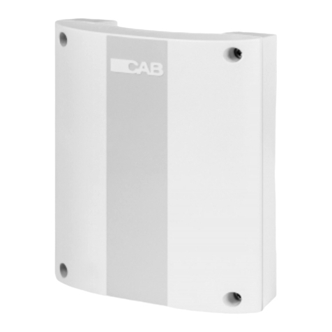
CAB CAB CL.ES.RR User manual

CL.ES.RR
CENTRALE DI COMANDO
CONTROL UNIT
CENTRALE DE COMMANDE
CENTRAL DE MANDO
Manuale istruzioni
Operating instructions
Livret d’instructions
Manual de instrucciones


F2,5A
R
A
D
I
O
ANT
WINDM
230Vac
50Hz
78910 11123456
91011
12 345678
L2 SP2
RESET
TR1
TR1
SW1
L1
L1
BZ
MOT
15
Km/h
1
Km/h
35
Km/h
abLN
a b
MOT
20
Km/h
1
Km/h
45
Km/h
Op. COMCOM Cl.Op.Cl.
LN
Op.COM
COM
Cl.Op. Cl.
WINDM
230Vac
50Hz
CL.ES.RR

AVVERTENZE
Questo manuale è destinato esclusivamente
a personale qualificato per l’installazione e la
manutenzione di aperture automatiche. Nessuna
informazione qui presente è di interesse o di utilità
per l’utente finale.
Conservare questo manuale per futuri utilizzi.
L’installatore deve fornire tutte le informazioni
relative al funzionamento automatico, manuale
e di emergenza dell’automazione, e consegnare
all’utilizzatore dell’impianto le istruzioni d’uso.
•Prevedere sulla rete di alimentazione un in-
terruttore/sezionatore onnipolare con distanza
d’apertura dei contatti uguale o superiore a 3 mm.
Verificare che a monte dell’impianto elettri-
co vi sia un interruttore differenziale e una
protezione di sovracorrente adeguati.
Alcune tipologie di installazione richiedono il colle-
gamento dell’anta ad un impianto di messa a terra
rispondente alle vigenti norme di sicurezza.
L’installazione elettrica e la logica di funzionamento
devono essere in accordo con le normative vigenti.
I conduttori alimentati con tensioni diverse, devono
essere fisicamente separati, oppure devono essere
adeguatamente isolati con isolamento supplemen-
tare di almeno 1 mm.
I conduttori devono essere vincolati da un fissaggio
supplementare in prossimità dei morsetti.
Durante gli interventi di installazione, manutenzio-
ne e riparazione, togliere l’alimentazione prima di
accedere alle parti elettriche.
Ricontrollare tutti i collegamenti fatti prima di dare
tensione.
Gli ingressi N.C. non utilizzati devono essere pon-
ticellati.
Le descrizioni e le illustrazioni presenti in questo
manuale non sono impegnative. Lasciando inal-
terate le caratteristiche essenziali del prodotto il
fabbricante si riserva il diritto di apportare qualsiasi
modifica di carattere tecnico, costruttivo o commer-
ciale senza impegnarsi ad aggiornare la presente
pubblicazione.
Dichiarazione CE di conformità
Dichiarazione in accordo alle Direttive 2004/108/CE(EMC); 2006/95/CE(LVD)
Fabbricante: Automatismi CAB Srl..
Indirizzo:Via della Tecnica,10 (z.i.) - 36010 Velo d’Astico (VI) - Italia
Dichiara che il prodotto: CL.ES.RR
è conforme alle condizioni delle seguenti Direttive CE:
• DIRETTIVA 2004/108/CE DEL PARLAMENTO EUROPEO E DEL CONSIGLIO del 15 dicembre 2004
concernente il ravvicinamento delle legislazioni degli Stati membri relative alla compatibilità elettromagnetica e
che abroga la direttiva 89/336/CEE, secondo le seguenti norme armonizzate:
EN 61000-6-2:2005, EN 61000-6-3:2007.
• DIRETTIVA 2006/95/CE DEL PARLAMENTO EUROPEO E DEL CONSIGLIO del 12 dicembre 2006
concernente il ravvicinamento delle legislazioni degli Stati membri relative al materiale elettrico destinato ad essere
adoperato entro taluni limiti di tensione, secondo le seguenti norme armonizzate:
EN 60335-1:2002 + A1:2004 + A11:2004 + A12:2006 + A2:2006 + A13:2008; EN 60335-2-103:2003.
se applicabile:
• DIRETTIVA 1999/5/CE DEL PARLAMENTO EUROPEO E DEL CONSIGLIO del 9 marzo 1999 riguardan-
te le apparecchiature radio e le apparecchiature terminali di telecomunicazione e il reciproco riconoscimento della
loro conformità, secondo le seguenti norme armonizzate: ETSI EN 301 489-3 V1.4.1 (2002) + ETSI EN 301 489-1
V1.4.1 (2002) + ETSI EN 300 220-3 V1.1.1 (2000) + EN 60950-1 (2001)
Benincà Luigi, Responsabile legale.
Velo d’Astico, 15/02/2010.

CENTRALE DI COMANDO CL.ES.RR
1) DESCRIZIONE
La centrale di comando CL.ES.RR è in grado di comandare 1 motore elettromeccanico tubolare per tende
da sole e tapparelle fino a 300W.
La centrale ha integrate le funzioni per la protezione in caso di vento eccessivo.
2) ACCESSORI
Alla centrale possono essere abbinati i seguenti accessori:
CL.W: anemometro completo di staffa per il fissaggio.
T4WV-C: trasmettitore 4 canali rolling-code (
NON UTILIZZARE T2WV-C
).
3) COLLEGAMENTI ELETTRICI
Morsetto Funzione Descrizione
4,6 Fase, Neutro Alimentazione centrale 230Vac 50Hz
7,8,9 Comando motore Comandi di apertura/chiusura motore:
- COM(9): comune comando;
- Op(8): contatto APRE;
- Cl(7): contatto CHIUDE.
Utilizzare esclusivamente pulsanti a ritorno automatico.
10,11 Sensore vento Collegamento sensore vento:
- a(10): comune sensori;
- b(11): segnale vento.
RADIO Modulo radio integrato frequenza di funzionamento 433,92 MHz.
ANT Antenna integrata Antenna a filo.
2,3,5 Collegamento motore Contatti per motore:
- COM(5): comune motore;
- Op(3): contatto motore APRE;
- Cl(2): contatto motore CHIUDE.
4) GESTIONE SENSORE VENTO
Nel caso in cui venga collegato alla centrale un sensore per il monitoraggio del vento proseguire come segue:
collegare il sensore(anemometro) all’ingresso prefissato(vedi schema) ed impostare tramite il trimmer TR1
la velocità del vento desiderata (vedi capitolo “FUNZIONE TRIMMER”).
Durante tutto il periodo dell’allarme vento e gli 8 minuti successivi, non è possibile muovere la tenda tramite
i pulsanti. Terminato tale tempo i comandi si ripristinano automaticamente.
5) FUNZIONE TRIMMER
Per la regolazione del sensore vento, selezionare la velocità desiderata
agendo sul trimmer TR1, come in figura:
6) FUNZIONAMENTO
Per il comando del motore si usano i pulsanti con ritorno automatico
oppure la trasmittente radio:
Funzionamento pulsanti: ad una pressione di 1 secondo la tenda si
muove nel verso richiesto, fino al termine della corsa determinato dal
finecorsa del motore. Nel caso si debba fermare la corsa prima del
tempo, premere il pulsante corrispondente al senso inverso del moto.
Funzionamento trasmittente:
alla pressione del tasto 1 il cancello si chiude; alla pressione del tasto 3 il cancello si apre. Nel caso si debba
fermare la corsa prima del tempo, premere il pulsante corrispondente al senso inverso del moto.
Priorità di intervento: nel caso in cui vengano dati più comandi contemporaneamente, ad esempio aper-
tura della tenda e allarme vento, le priorità sono le seguenti:
1° anemometro >> 2° trasmittente o pulsante.
F2,5A
R
A
D
I
O
ANT
WINDM
230Vac
50Hz
78910 11123456
91011
12 345678
L2 SP2
RESET
TR1
TR1
SW1
L1
L1
BZ
MOT
15
Km/h
1
Km/h
35
Km/h
abLN
a b
MOT
20
Km/h
1
Km/h
45
Km/h
Op. COMCOM Cl.Op.Cl.
LN
Op.COM
COM
Cl.Op. Cl.
WINDM
230Vac
50Hz

7) REGOLAZIONE SW1
Il ponte SW1 serve per regolare l’evantuale riapertura della tenda a seguito di un allarme vento:
Ponticello SW1 aperto: terminato l’allarme vento la tenda si riposiziona dove si trovava.
Se era aperta si riapre.
Ponticello SW1 chiuso: la tenda una volta chiusa, con allarme vento, rimane chiusa.
Per riaprirla si deve inviare un comando di apertura.
8) RESET INSTALLAZIONE
Alla prima installazione, dopo aver verificato il funzionamento dell’allarme vento, al raggiungimento della
velocità stabilita la tenda deve salire. Per eliminare il tempo di attesa di 8 minuti, è sufficiente togliere e
ridare tensione alla centrale.
9) PROGRAMMAZIONE TRASMITTENTE (max. 14 trasmet-
titori)
Per programmare il trasmettitore premere e rilasciare il tasto
SP2: il LED L2 si accende e il buzzer emette un suono conti-
nuo. Premere il tasto 1 del trasmettitore per circa 4 secondi
allo spegnimento del buzzer, rilasciare il tasto del trasmettitore
e ripremerlo nuovamente per 2 secondi: il LED L2 lampeggia
per tre volte ed il buzzer suona con intermittenza; il trasmetti-
tore è codificato nella scheda.
Se non si sente il suono intermittente per 15 secondi, ripete-
re le operazioni precedentemente descritte.
F2,5A
R
A
D
I
O
ANT
WINDM
230Vac
50Hz
78910 11123456
91011
12 345678
L2 SP2
RESET
TR1
TR1
SW1
L1
L1
BZ
MOT
15
Km/h
1
Km/h
35
Km/h
abLN
a b
MOT
20
Km/h
1
Km/h
45
Km/h
Op. COMCOM Cl.Op.Cl.
LN
Op.COM
COM
Cl.Op. Cl.
WINDM
230Vac
50Hz
F2,5A
R
A
D
I
O
ANT
WINDM
230Vac
50Hz
78910 11123456
91011
12 345678
L2 SP2
RESET
TR1
TR1
SW1
L1
L1
BZ
MOT
15
Km/h
1
Km/h
35
Km/h
abLN
a b
MOT
20
Km/h
1
Km/h
45
Km/h
Op. COMCOM Cl.Op.Cl.
LN
Op.COM
COM
Cl.Op. Cl.
WINDM
230Vac
50Hz
SW1
SW1
10) CANCELLAZIONE DELLA MEMORIA CENTRALE
Per cancellare dalla memoria della centralina tutte le trasmittenti codificate, è sufficiente tenere premuto il
tasto SP2 per 10-15 secondi, finchè il LED L2 rosso inizia a lampeggiare.
11) VISUALIZZAZIONE DEI LED (L1,L2)
LED rosso L2 lampeggiante c’è stato un allarme vento; la centrale manda immediatamente
un segnale di chiusura a tutti i motori, che si possono riaprire
dopo 10 minuti.
MOT
1
ON
16
F2,5A
MOT
2
MOT
3
MOT
4
M1ALL
JM1 JM2 JM3 ANT
LN Op. COM Cl.
Op.
COM
Cl.
Op. COM Cl. Op. COM Cl. Op. COM Cl.
Op. Cl. Op. Cl. Op. Cl. Op. Cl.
COMCOM COM
abcdefg
SP2
RT1
SW
COM
M2M3M4
R
A
D
I
O
0
Klux
8
Klux
12
Klux
25
Klux 32
Klux
45
Klux
50
Klux
DL1
DL2
Tasto 1
CHIUDE
Tasto 2
Tasto 4
Tasto 3
APRE
T4WV-C
DATI TECNICI
Alimentazione centrale di comando 230 Vac
Fusibile 2,5 A
Temperatura di esercizio -10°C / +60°C
Tempo di lavoro 2 minuti
Uscita motore 1 motore 230 Vac
Potenza massima motore 300W
Grado di protezione IP56
Ricevitore radio 433,92 MHz integrato

WARNINGS
This manual has been especially written to be use
by qualified fitters.
None of the information provide in this manual
can be considered as being of interest for the end
users.
Preserve this manual for future needs.
The technician has to furnish all the information
related to the step by step function, the manual
and the emergency function of the operator, and to
deliver the manual to the final user.
•Foresee on the supply net an onnipolar switch
or selector with distance of the contacts equal
or superior to 3 mms.
Verify that of the electrical system there is an awry
differential interrupter and overcurrent protection.
Some typologies of installation require the connec-
tion of the shutter to be link at a conductive mass of
the ground according to the regulations in force.
The electrical installation and the operating logic must
comply with the regulations in force.
The leads fed with different voltages must be physi-
cally separate, or they must be suitably insulated with
additional insulation of at least 1 mm.
The leads must be secured with an additional fixture
near the terminals.
During installation, maintenance and repair, interrupt
the power supply before opening the lid to access the
electrical parts
Check all the connections again before switching on
the power.
The unused N.C. inputs must be bridged.
The descriptions and the present illustrations in this ma-
nual are not binding. Leaving the essential characteristi-
cs of the product unchanged, the manufacturer reserves
himself the right to bring any change of technical, con-
structive or commercial character without undertaking
himself to update the present publication.
EC declaration of confirmity
Declaration pursuant to Directives 2004/108/EC(EMC); 2006/95/EC(LVD)
Manufacturer: Automatismi CAB Srl.
Address: Via della Tecnica,10 (z.i.) - 36010 Velo d’Astico (VI) - Italia
Declares that the product: CL.ER.RR
is compliant with the conditions of the following EC Directives:
• DIRECTIVE 2004/108/EC OF THE EUROPEAN PARLIAMENT AND COUNCIL of December 15 2004
regarding the approximation of the legislations of the member States relative to electromagnetic compatibility and
that repeals directive 89/336/CEE, according to the following concurred norms:
EN 61000-6-2:2005, EN 61000-6-3:2007.
• DIRECTIVE 2006/95/EC OF THE EUROPEAN PARLIAMENT AND THE COUNCIL of December 12
2006 concerning the approximation of the legislations of the member States relative to electrical material destined
to be used within certain voltage limits, according to the following concurred regulations:
EN 60335-1:2002 + A1:2004 + A11:2004 + A12:2006 + A2:2006 + A13:2008; EN 60335-2-103:2003.
if applicable :
• DIRECTIVE 1999/5/EC OF THE EUROPEAN PARLIAMENT AND THE COUNCIL of March 9 1999
regarding radio devices and terminal and telecommunications devices and the reciprocal recognisances of their
conformity, according to the following concurred regulations: ETSI EN 301 489-3 V1.4.1 (2002) + ETSI EN 301
489-1 V1.4.1 (2002) + ETSI EN 300 220-3 V1.1.1 (2000) + EN 60950-1 (2001)
Benincà Luigi, Legal manager.
Velo d’Astico, 15/02/2010.

CL.ES.RR CONTROL UNIT
1) DESCRIPTION
The CL.ES.RR control unit is able to control 1 electro-mechanical tubular motor for sun shade curtains and
rolling shutters.
The control unit features integrated functions for the protection in the event of excessive wind.
2) ACCESSORIES
The control unit can be equipped with the following accessories:
CL.W: anemometer complete with fixing bracket.
T4WV-C: 4-channel, rolling code transmitter (
DO NOT USE T2WV-C
).
3) WIRE DIAGRAM
Terminal Function Description
4,6 Phase, Neutral Control unit power supply, 230VAC 50Hz
7,8,9 Motor control Motor opening/closing controls:
- COM(9): command, common;
- Op(8): OPEN contact;
- Cl(7): CLOSE contact.
Use auto-default push buttons only.
10,11 Wind sensor Wind sensor connection:
- a(10): sensors, common;
- b(11): wind signal.
RADIO Integrated radio module Operating frequency: 433.92MHz
ANT Integrated antenna Wire antenna
2,3,5 Motor connection Motor contacts:
- COM(5): motor, common;
- Op(3): OPEN motor contact;
- Cl(2): CLOSE motor contact.
4) WIND SENSOR MANAGEMENT
If a wind sensor is connected to the control unit, proceed as follows:
connect the sensor (anemometer) to the preset input (see diagram) and set the desired wind speed by using
the TR1 trimmer (see section “TRIMMER FUNCTIONS”).
During the entire period of wind alarm and the following 8 minutes, the curtain cannot be operated by means
of the push-buttons. When this time has elapsed, the controls are reset automatically.
5) TRIMMER FUNCTIONS
To adjust wind speed, select the desired speed by using the TR1 trim-
mer, as shown in the figure:
6) OPERATION
To control the motor, use auto-default push buttons or buttons of the
stable type.
Operation of push buttons: if the buttons are pressed for one se-
cond, the sun shade curtain moves in the required direction until it
reaches the end of stroke set by the motor limit switch. If the stroke
must be stopped before time, press the button corresponding to the
reverse movement direction.
Transmitter operation:
Button1 = CLOSE / Button3 = OPEN. If the stroke must be stopped before time, press the button corre-
sponding to the reverse movement direction.
Triggering priorities: should more than one control signal be sent simultaneously, for example curtain
opening command and wind alarm, priorities are the following:
1st anemometer >> 2nd transmitter or push button.
F2,5A
R
A
D
I
O
ANT
WINDM
230Vac
50Hz
78910 11123456
91011
12 345678
L2 SP2
RESET
TR1
TR1
SW1
L1
L1
BZ
MOT
15
Km/h
1
Km/h
35
Km/h
abLN
a b
MOT
20
Km/h
1
Km/h
45
Km/h
Op. COMCOM Cl.Op.Cl.
LN
Op.COM
COM
Cl.Op. Cl.
WINDM
230Vac
50Hz

F2,5A
R
A
D
I
O
ANT
WINDM
230Vac
50Hz
78910 11123456
91011
12 345678
L2 SP2
RESET
TR1
TR1
SW1
L1
L1
BZ
MOT
15
Km/h
1
Km/h
35
Km/h
abLN
a b
MOT
20
Km/h
1
Km/h
45
Km/h
Op. COMCOM Cl.Op.Cl.
LN
Op.COM
COM
Cl.Op. Cl.
WINDM
230Vac
50Hz
F2,5A
R
A
D
I
O
ANT
WINDM
230Vac
50Hz
78910 11123456
91011
12 345678
L2 SP2
RESET
TR1
TR1
SW1
L1
L1
BZ
MOT
15
Km/h
1
Km/h
35
Km/h
abLN
a b
MOT
20
Km/h
1
Km/h
45
Km/h
Op. COMCOM Cl.Op.Cl.
LN
Op.COM
COM
Cl.Op. Cl.
WINDM
230Vac
50Hz
SW1
SW1
TECHNICAL DATA
Contol unit supply 230 Vac
Fuse 2,5 A
Operating temperature -10°C / +60°C
Time of work 2 minutes
Output supply 1 motor 230 Vac
Power maximum motor 300W
Protection level IP56
Radio receiver 433,92 MHz integrated
7) SW1 ADJUSTMENT
The SW1 jack adjusts the possible re-opening of the sun shade curtain after a wind alarm:
SW1 jack open:
when the wind alarm stops, the curtain moves again to the original position.
If the sun shade curtain was open, it will open again.
SW1 jack closed: when closed, the curtain remains closed when a wind alarm triggers.
To re-open it, an opening control signal must be sent.
8) INSTALLATION RESET
At first installation, after checking the good operation of the
wind alarm, when the wind speed is reached the sun shade
curtain must close. To avoid waiting for 8 minutes, power the
control unit on and off.
9) HOW TO PROGRAMME THE TRANSMITTER (14 tran-
smitters max)
To programme the transmitter, press and release the SP2
key: the L2 LED switches on and the buzzer makes a con-
tinuous sound. Press key 1 of the transmitter for around 4
seconds from the buzzer switching off. Release the transmit-
ter key and press it again for 2 seconds: the L2 LED flashes
three times and the buzzer makes an intermittent sound. The transmitter code is now stored in the memory
card.
If the intermittent sound is not heard for 15 seconds, repeat the above-mentioned steps.
10) HOW TO ERASE THE CENTRAL MEMORY
To erase all transmitter codes from the control unit memory, press the SP2 key and keep it pressed for 10-
15 seconds, until the red L2 LED starts flashing.
11) DISPLAY OF THE LEDs (L1, L2)
Red L2 LED flashes a wind alarm has triggered. The control unit sends a closing control signal to
all motors; they can start again for re-opening after 10 minutes.
MOT
1
ON
16
F2,5A
MOT
2
MOT
3
MOT
4
M1ALL
JM1 JM2 JM3 ANT
LN Op. COM Cl.
Op.
COM
Cl.
Op. COM Cl. Op. COM Cl. Op. COM Cl.
Op. Cl. Op. Cl. Op. Cl. Op. Cl.
COMCOM COM
abcdefg
SP2
RT1
SW
COM
M2M3M4
R
A
D
I
O
0
Klux
8
Klux
12
Klux
25
Klux 32
Klux
45
Klux
50
Klux
DL1
DL2
Tasto 1
CHIUDE
Tasto 2
Tasto 4
Tasto 3
APRE
T4WV-C

RECOMMENDATIONS GÉNÉRALES
Ce manuel est destiné exclusivement au personnel
qualifié pour l’installation et la maintenance des
ouvertures automatiques.
Aucune information donnée dans ce manuel ne sera
d’intérêt ou d’utilité a l’utilisateur final.
Conservez ce manuel pour de futures utilisations.
L’installateur doit donner tout renseignement relatif
au fonctionnement automatique, manuel e de se-
cours de l’automatisme, et consigner à l’utilisateur
du produit le livret d’instructions.
•Il faut prévoir dans le réseau d’alimentation
un interrupteur/sectionneur omnipolaire avec
une distance d’ouverture des contacts égale ou
supérieure à 3 mm.
Vérifier la présence en amont de l’installation électri-
que d’un disjoncteur différentiel et d’une protection
contre la surintensité adéquats. Si nécessaire,
raccorder la porte ou le portail motorisé à une instal-
lation de mise à la terre réalisée conformément aux
prescriptions des normes de sécurité en vigueur.
L’installation électrique et la logique de fonctionnement
doivent être conformes aux normes en vigueur.
Les conducteurs alimentés à des tensions différentes
doivent être séparés physiquement ou bien, ils doivent
être isolés en manière appropriée avec une gaine
supplémentaire d’au moins 1 mm.
Les conducteurs doivent être assurés par une fixation
supplémentaire à proximité des bornes.
Pendant toute intervention d’installation, maintenance
et réparation, couper l’alimentation avant de procéder
à toucher les parties électriques.
Recontrôler toutes les connexions faites avant d’ali-
menter la logique de commande.
Les entrées N.F. non utilisées doivent être shuntées
Les descriptions et les illustrations contenues dans ce
manuel ne sont pas contraignantes. Le fabricant se
réserve le droit d’apporter n’importe quelle modification
du coté technique, de construction ou commerciale,
en laissant inaltérées les caractéristiques essentielles
du produit sans être contraint à mettre au jours cette
publication.
Déclaration CE de conformité
Déclaration en accord avec les Directives 2004/108/CE (EMC); 2006/95/CE(LVD)
Fabricant:Automatismi CAB Srl..
Adresse:Via della Tecnica,10 (z.i.) - 36010 Velo d’Astico (VI) - Italie
Déclare que le produit: CL.ES.RR
est conforme aux conditions des Directives CE suivantes:
• DIRECTIVE 2004/108/CE DU PARLEMENT EUROPEEN ET DU CONSEIL du 15 décembre 2004 con-
cernant le rapprochement des législations des Etats membres relatives à la compatibilité électromagnétique et qui
abroge la directive 89/336/CEE, selon les normes harmonisées suivantes:
EN 61000-6-2:2005, EN 61000-6-3:2007.
• DIRECTIVE 2006/95/CE DU PARLEMENT EUROPEEN ET DU CONSEIL du 12 décembre 2006 concer-
nant le rapprochement des législations des Etats membres relatives au matériel électrique destiné à être utilisé dans
certaines limites de tension, selon les normes harmonisées suivantes:
EN 60335-1:2002 + A1:2004 + A11:2004 + A12:2006 + A2:2006 + A13:2008; EN 60335-2-103:2003.
si elle est applicable:
• DIRECTIVE 1999/5/CE DU PARLEMENT EUROPEEN ET DU CONSEIL du 9 mars 1999 concernant les
appareils radio et les équipements terminaux de communication et la reconnaissance réciproque de leur conformité,
selon les normes harmonisées suivantes: ETSI EN 301 489-3 V1.4.1 (2002) + ETSI EN 301 489-1 V1.4.1 (2002) +
ETSI EN 300 220-3 V1.1.1 (2000) + EN 60950-1 (2001)
Benincà Luigi, Responsable légal.
Velo d’Astico, 15/02/2010.

CENTRALE DE COMMANDE CL.ES.RR
1) DESCRIPTION
La centrale de commande CL.ES.RR est en mesure d’entrainer 1 moteur tubulaire électromécanique pour
volets roulants et stores bannes jusqu’à 300W.
La centrale intègre les fonctions pour la protection en cas de vent excessif.
2) ACCESSOIRES
La centrale peut être fournie avec les accessoires ci de suite:
CL.W: anémomètre avec bride de fixation.
T4WV-C: émetteur quadricanal rolling-code (
NE PAS UTILISER T2WV-C
).
3) BRANCHEMENTS ELECTRIQUES
Serre-joints Fonction Description
4,6 Phase, Neutre Alimentation centrale 230Vac 50Hz
7,8,9 Commande moteur Commandes ouverture/fermeture moteur:
- COM(9): commune commande;
- Op(8): contact OUVRE;
- Cl(7): contact FERME.
Utiliser exclusivement interrupteurs à position fixe ou
momentanée.
10,11 Capteur vent Branchement capteur vent:
- a(10): commun capteurs;
- b(11): signal vent.
RADIO Module radio intégré Fréquence de fonctionnement 433,92 MHz.
ANT Antenne intégrée Antenne à fil.
2,3,5 Branchement moteur Contacts pour moteur:
- COM(5): commun moteur;
- Op(3): contact moteur OUVRE;
- Cl(2): contact moteur FERME.
4) GESTION CAPTEUR VENT
Ci de suite le fonctionnement si à la centrale des capteurs pour le monitorage du vent:
brancher le capteur (anémomètre) à l’entrée préfixée (voir schéma) et saisir à l’aide du trimmer TR1 la vitesse
du vent désirée (voir chapitre “FONCTION TRIMMER”).
Durant toute la période de l’alarme vent et les 8 minutes qui suivent, impossible de déplacer le store banne
à l’aide des boutons pressoirs. Après ce temps les commandes sont restaurées automatiquement.
5) FONCTION TRIMMER
Pour le réglage du capteur vent, sélectionner la vitesse désirée en agissant sur le trimmer TR1, comme
dans la figure:
6) FONCTIONNEMENT
Pour commander le moteur utiliser des interrupteurs à position fixe
ou momentanée ou l’émetteur radio:
Fonctionnement des touches:
en appuyant sur la touche pendant 1
seconde le store banne avance dans le sens désiré, jusqu’à la fin de
la course déterminée par le fin de course du moteur. Si l’on désire ar-
rêter le store banne avant la fin de la course, appuyer sur l’interrupteur
correspondant au mouvement en sens inverse.
Fonctionnement émetteur:
Touche1 = FERME / Touche3 = OUVRE.
Si l’on désire arrêter le store
banne avant la fin de la course, appuyer sur l’interrupteur correspondant au mouvement en sens inverse.
Priorité d’intervention: si plusieurs commandes sont données simultanément, par exemple ouverture du
store banne et alarme vent, les priorités sont les suivantes:
1° anémomètre >> 2° émetteur ou bouton pressoir.
F2,5A
R
A
D
I
O
ANT
WINDM
230Vac
50Hz
78910 11123456
91011
12 345678
L2 SP2
RESET
TR1
TR1
SW1
L1
L1
BZ
MOT
15
Km/h
1
Km/h
35
Km/h
abLN
a b
MOT
20
Km/h
1
Km/h
45
Km/h
Op. COMCOM Cl.Op.Cl.
LN
Op.COM
COM
Cl.Op. Cl.
WINDM
230Vac
50Hz

7) REGLAGE SW1
Le pont SW1 sert pour régler l’éventuelle réouverture du store banne après une alarme vent:
Pontet SW1 ouvert:
Une fois l’alarme vent cessé le store banne regagne sa place.
S’il était ouvert il se rouvre
Pontet SW1 fermé:
Une fois fermé, suite à l’alarme vent, le store banne reste fermé.
Pour le rouvrir il faut envoyer une commande d0ouverture.
8) REMISE À ZÉRO INSTALLATION
Lors de la première installation, après avoir vérifié le fonctionnement de l’alarme vent, et une fois que la
vitesse préfixée est atteinte, le store banne doit remonter. Pour limiter le temps d’attente de 8 minutes, il
suffit de couper et de restaurer la tension à la centrale.
9) PROGRAMMATION EMETTEUR (max. 14 émetteurs)
Pour programmer l’émetteur appuyer et relâcher la touche
SP2: la LED L2 s’allume et le buzzer émet un son continu.
Appuyer sur la touche 1 de l’émetteur pendant environ 4
seconde lorsque le buzzer s’éteint, relâcher la touche de
l’émetteur et appuyer à nouveau pendant 2 secondes : la
LED L2 clignote pendant trois fois et le buzzer sonne avec
intermittence ; l’émetteur est encodé dans la carte .
Si l’on n’entend pas le son intermittent pendant 15 seconde,
répéter les opérations ci-dessus.
10) EFFACEMENT DE LA MÉMOIRE CENTRALE
Pour effacer de la mémoire de la centrale tous les émetteurs codifiés, il suffit de garder pressée la touche
SP2 pendant 10-15 secondes, jusqu’à ce que la LED L2 rouge commence à clignoter.
11) AFFICHAGES DES LED (L1,L2)
LED rouge L2 clignotante Il y a eu une alarme vent; la centrale envoi immédiatement un signal de
fermeture à tous les moteurs, qui peuvent se rouvrir après 10 minutes.
F2,5A
R
A
D
I
O
ANT
WINDM
230Vac
50Hz
78910 11123456
91011
12 345678
L2 SP2
RESET
TR1
TR1
SW1
L1
L1
BZ
MOT
15
Km/h
1
Km/h
35
Km/h
abLN
a b
MOT
20
Km/h
1
Km/h
45
Km/h
Op. COMCOM Cl.Op.Cl.
LN
Op.COM
COM
Cl.Op. Cl.
WINDM
230Vac
50Hz
F2,5A
R
A
D
I
O
ANT
WINDM
230Vac
50Hz
78910 11123456
91011
12 345678
L2 SP2
RESET
TR1
TR1
SW1
L1
L1
BZ
MOT
15
Km/h
1
Km/h
35
Km/h
abLN
a b
MOT
20
Km/h
1
Km/h
45
Km/h
Op. COMCOM Cl.Op.Cl.
LN
Op.COM
COM
Cl.Op. Cl.
WINDM
230Vac
50Hz
SW1
SW1
DONNÉES TECHNIQUES
Alimentation centrale de commande 230 Vac
Fusible 2,5 A
Température de fonctionnement -10°C / +60°C
Temps de travail 2 minutes
Sortie Moteur 1 moteur 230 Vac
Puissance maximale moteur 300W
Dégrée de protection IP56
Récepteur radio 433,92 MHz intégrée
MOT
1
ON
16
F2,5A
MOT
2
MOT
3
MOT
4
M1ALL
JM1 JM2 JM3 ANT
LN Op. COM Cl.
Op.
COM
Cl.
Op. COM Cl. Op. COM Cl. Op. COM Cl.
Op. Cl. Op. Cl. Op. Cl. Op. Cl.
COMCOM COM
abcdefg
SP2
RT1
SW
COM
M2M3M4
R
A
D
I
O
0
Klux
8
Klux
12
Klux
25
Klux 32
Klux
45
Klux
50
Klux
DL1
DL2
Tasto 1
CHIUDE
Tasto 2
Tasto 4
Tasto 3
APRE
T4WV-C

ADVERTENCIAS
Este manual está destinado exclusivamente a perso-
nal cualificado para la instalación y el mantenimiento
de aperturas automáticas.
Ninguna información de las aquí presentadas es de
interés o de utilidad para el usuario final.
Guardar este manual para futuras consultas.
El instalador debe proporcionar todas las informacio-
nes relativas al funcionamiento automático, manual
y de emergencia de la automatización y entregar al
usuario de la instalación las instrucciones de uso.
•Prever en la red de alimentación un interrup-
tor/cortacircuitos omnipolar con distancia de
apertura de los contactos igual o mayor que 3 mm.
Comprobar que entre el aparato y la red eléctrica
general haya un interruptor diferencial y una pro-
tección contra sobrecorriente adecuados.
Algunos tipos de instalación requieren que se co-
necte la hoja con una instalación de puesta a tierra
conforme a las vigentes normas de seguridad.
La instalación eléctrica y la lógica de funcionamiento
deben cumplir las normas vigentes.
Los conductores alimentados con tensiones distintas
deben estar físicamente separados, o bien deben estar
adecuadamente aislados con aislamiento suplementa-
rio de por lo menos 1 mm.
Los conductores deben estar vinculados por una fijación
suplementaria cerca de los bornes.
Durante las operaciones de instalación, mantenimiento
y reparación, cortar la alimentación antes de acceder a
las partes eléctricas.
Comprobar todas las conexiones efectuadas antes de
dar la tensión.
Las entradas N.C. no utilizadas deben estar puen-
teadas.
Las descripciones y las ilustraciones presentadas en
este manual no son vinculantes. Sin cambiar las ca-
racterísticas esenciales del producto, el fabricante se
reserva el derecho de aportar cualquier modificación de
carácter técnico,constructivo o comercial sin obligación
de actualizar la presente publicación.
Declaración CE de conformidad
Declaración según las directivas 2004/108/CE(EMC); 2006/95/CE(LVD)
Fabricante:Automatismi CAB Srl..
Domicilio:Via della Tecnica,10 (z.i.) - 36010 Velo d’Astico (VI) - Italie
Declara que el producto: CL.ES.RR
cumple con las condiciones estipuladas en la siguientes Directivas CE:
• DIRECTIVA 2004/108/CE DEL PARLAMENTO EUROPEO Y DEL CONSEJO del 15 de diciembre de 2004
con respecto a la aproximación de las legislaciones de estados miembros sobre la compatibilidad electromagnética
y se deroga la Directiva 89/336/CEE, de acuerdo con las siguientes normas armonizadas:
EN 61000-6-2:2005, EN 61000-6-3:2007.
• DIRECTIVA 2006/95/CE DEL PARLAMENTO EUROPEO Y DEL CONSEJO del 12. de diciembre de 2006
con respecto a la aproximación de las legislaciones de estados miembros sobre el material eléctrico destinado a
trabajar dentro de tales límites de tensión según las siguientes normas armonizadas:
EN 60335-1:2002 + A1:2004 + A11:2004 + A12:2006 + A2:2006 + A13:2008; EN 60335-2-103:2003.
si procede:
• DIRECTIVA 1999/5/CE DEL PARLAMENTO EUROPEO Y DEL CONCEJO del 9 de marzo 1999 con sobre
equipos de radio y equipos terminales de telecomunicación y reconocimiento mutuo de su conformidad, de acuerdo
con las siguientes normas armonizadas. ETSI EN 301 489-3 V1.4.1 (2002) + ETSI EN 301 489-1 V1.4.1 (2002) +
ETSI EN 300 220-3 V1.1.1 (2000) + EN 60950-1 (2001)
Benincà Luigi, Responsable legal.
Velo d’Astico, 15/02/2010.

CENTRAL DE CONTROL CL.ES.RR
1) DESCRIPCIÓN
La central de control CL.ES.RR es capaz de controlar 1 motor electromecánico tubular para toldos parasol
y persianas de hasta 300W.
La central tiene incorporadas las funciones para la protección en caso de fuerte viento.
2) ACCESORIOS
Con la central se pueden combinar los accesorios siguientes:
CL.W: anemómetro completo de soporte para su fijación.
T4WV-C: transmisor de 4 canales rolling-code (
NO UTILIZAR T2WV-C
).
3) CONEXIONES ELÉCTRICAS
Borne Función Descripción
4,6 Fase, Neutro Alimentación central 230Vca - 50Hz.
7,8,9 Mando motor Mandos de apertura/cierre motor:
- COM(9): común mando;
- Op(8): contacto ABRE;
- Cl(7): contacto CIERRA.
Utilizar exclusivamente pulsadores con vuelta automática
a la posición de partida.
10,11 Sensor de viento Conexión sensor de viento:
- a(10): común sensores;
- b(11): señal de viento.
RADIO Módulo radio integrado Frecuencia de funcionamiento 433,92 MHz.
ANT Antena integrada Antena de hilo.
2,3,5 Conexión motor Contactos para motor:
- COM(5): común motor;
- Op(3): contacto motor ABRE;
- Cl(2): contacto motor CIERRA.
4) GESTIÓN DEL SENSOR DE VIENTO
Si con la central se conecta un sensor para la monitorización del viento, actuar como sigue:
conectar el sensor (anemómetro) en la entrada preestablecida (véase el esquema) y configurar, mediante el
condensador de ajuste TR1, la velocidad del viento que se desea (véase el capítulo “FUNCIÓN TRIMMER”).
Durante todo el periodo de la alarma por viento y los 8 minutos siguiente, no es posible mover el toldo me-
diante los pulsadores. Terminado dicho tiempo los mandos se restablecen automáticamente.
5) FUNCIÓN TRIMMER
Para ajustar el sensor del viento, seleccionar la velocidad deseada
actuando sobre el condensador de ajuste (trimmer) TR1, como mos-
trado en la figura:
6) FUNCIONAMIENTO
Para controlar el motor se utilizan los pulsadores con vuelta automática a la
posición inicial o bien el transmisor radio:
Funcionamiento con pulsadores: con una presión de 1 segundo el
toldo se mueve en la dirección deseada, hasta el final de la carrera
determinado por el final de carrera del motor. Si se tiene que parar la
carrera antes del tiempo, apretar el pulsador correspondiente a la dirección contraria del movimiento.
Funcionamiento con transmisor:
Botón1 = CIERRA / Botón3 = ABRE.
Si se tiene que parar la carrera antes del tiempo, apretar el pulsador
correspondiente a la dirección contraria del movimiento.
Prioridad de actuación: en el caso de que se den varios mandos simultáneamente, por ejemplo de aper-
tura del toldo y de alarma por viento, las prioridades son las siguientes:
1° anemómetro >> 2° transmisor o pulsador.
F2,5A
R
A
D
I
O
ANT
WINDM
230Vac
50Hz
78910 11123456
91011
12 345678
L2 SP2
RESET
TR1
TR1
SW1
L1
L1
BZ
MOT
15
Km/h
1
Km/h
35
Km/h
abLN
a b
MOT
20
Km/h
1
Km/h
45
Km/h
Op. COMCOM Cl.Op.Cl.
LN
Op.COM
COM
Cl.Op. Cl.
WINDM
230Vac
50Hz

F2,5A
R
A
D
I
O
ANT
WINDM
230Vac
50Hz
78910 11123456
91011
12 345678
L2 SP2
RESET
TR1
TR1
SW1
L1
L1
BZ
MOT
15
Km/h
1
Km/h
35
Km/h
abLN
a b
MOT
20
Km/h
1
Km/h
45
Km/h
Op. COMCOM Cl.Op.Cl.
LN
Op.COM
COM
Cl.Op. Cl.
WINDM
230Vac
50Hz
F2,5A
R
A
D
I
O
ANT
WINDM
230Vac
50Hz
78910 11123456
91011
12 345678
L2 SP2
RESET
TR1
TR1
SW1
L1
L1
BZ
MOT
15
Km/h
1
Km/h
35
Km/h
abLN
a b
MOT
20
Km/h
1
Km/h
45
Km/h
Op. COMCOM Cl.Op.Cl.
LN
Op.COM
COM
Cl.Op. Cl.
WINDM
230Vac
50Hz
SW1
SW1
DATOS TÉCNICOS
Alimentación central de mando 230 Vac
Fusible 2,5 A
Temperatura de funcionamiento -10°C / +60°C
Tiempo de trabajo 2 minutos
Salida Motor 1 motor 230 Vac
Potencia máxima motor 300W
Grado de protección IP56
Receptor radio 433,92 MHz integrado
7) AJUSTE DE SW1
El puente SW1 sirve para ajustar la eventual reapertura del toldo después de una alarma por viento:
Puente SW1 abierto:
terminada la alarma por viento el toldo vuelve a posicionarse donde estaba.
Si estaba abierto vuelve a abrirse.
Puente SW1 cerrado:
el toldo una vez cerrado, con alarma por viento, queda cerrado.
Para volver a abrirlo se tiene que enviar un mando de apertura.
8) RESETEO DE LA INSTALACIÓN
Al efectuar la primera instalación, después de haber comprobado el funcionamiento de la alarma por viento,
al alcanzar la velocidad establecida el toldo tiene que subir. Para eliminar el tiempo de espera de 8 minutos,
basta quitar y volver a dar la tensión a la central.
9) PROGRAMACIÓN DEL TRANSMISOR (máx. 14 trans-
misores)
Para programar el transmisor apretar y soltar el botón SP2: el
LED L2 se enciende y el zumbador emite un sonido continuo.
Apretar el botón 1 del transmisor durante aproximadamente
4 segundos cuando se apaga el zumbador, soltar el botón
del transmisor y volver a apretarlo durante 2 segundos: el
LED L2 parpadea tres veces y el zumbador emite un sonido
intermitente; el transmisor está codificado en la tarjeta.
Si no se oye el sonido intermitente por 15 segundos, hay
que repetir las operaciones susodichas.
10) BORRADO DE LA MEMORIA DE LA CENTRAL
Para borrar de la memoria de la central todos los transmisores codificados, basta mantener apretado el
botón SP2 durante 10-15 segundos, hasta que el LED L2 rojo empieza a parpadear.
11) INDICACIÓN DE LOS LED (L1,L2)
LED rojo L2 intermitente ha habido una alarma por viento; la central envía inmediatamente una señal
de cierre a todos los motores, que pueden volver a abrirse transcurridos 10
minutos.
MOT
1
ON
16
F2,5A
MOT
2
MOT
3
MOT
4
M1ALL
JM1 JM2 JM3 ANT
LN Op. COM Cl.
Op.
COM
Cl.
Op. COM Cl. Op. COM Cl. Op. COM Cl.
Op. Cl. Op. Cl. Op. Cl. Op. Cl.
COMCOM COM
abcdefg
SP2
RT1
SW
COM
M2M3M4
R
A
D
I
O
0
Klux
8
Klux
12
Klux
25
Klux 32
Klux
45
Klux
50
Klux
DL1
DL2
Tasto 1
CHIUDE
Tasto 2
Tasto 4
Tasto 3
APRE
T4WV-C

AUTOMATISMI CAB Srl - Via della Tecnica,10 (z.i.) - 36010 Velo d’Astico (VI) (Italia) - Tel. 0445 741215 - Fax 0445 742094
CL8542711 02/2013 R2
Table of contents
Languages:
Other CAB Control Unit manuals