CAB SUBWAY SB.25AC Installer manual

APRICANCELLO OLEODINAMICO INTERRATO
UNDERGROUD OIL-HYDRAULIC AUTOMATION
HYDRAULISCHER UNTERFLUR TORANTRIEB
OUVRE PORTAIL OLEO-DYNAMIQUE ENTERRE’
ABRECANCELAS OLEODINÁMICO ENTERRADO
ELEKTROHYDRAULICZNY PODZIEMNY NAPĘD DO BRAM
SUBWAY
Manuale istruzioni e catalogo ricambi
Operating instructions and spare parts catalogue
Betriebsanleitung und Ersatzteilliste
Livret d’instructions et catalogue des pièces de rechange
Manual de instrucciones y catálogo de recambios
Książeczka z instrukcjami i katalog części wymiennych

1
2
3
11
8
9
10
6
12
7
13
14
15
4
2
3
16
17
5
C
2
3
1
23
Min 60 mm
B
RA
228 mm
100 mm
228 mm
400 mm
306 mm
320 mm
200mm
50 mm
Mod. A B
SB.SL 70mm 35mm
SB.KL 70mm 19mm
SB.BUSH 50mm 38mm

2
3
4
9
Min 60 mm
B
RA
228 mm
100 mm
228 mm
400 mm
306 mm
320 mm
200mm
50 mm
Mod. A B
SB.SL 70mm 35mm
SB.KL 70mm 19mm
SB.BUSH 50mm 38mm
5
Min 60 mm
B
RA
228 mm
100 mm
228 mm
400 mm
306 mm
320 mm
200mm
50 mm
Mod. A B
SB.SL 70mm 35mm
SB.KL 70mm 19mm
SB.BUSH 50mm 38mm
~ 40 cm
=
=
~
30 cm
~ 50 cm
6 7 8
100°
OPEN
100°
OPEN
SX DX

4
5
OPEN OPEN
100° 100°
10
SX DX
13 11
SX
OPEN
OPEN
DX
12
V
V
G B
14
15
GB
SX
OPEN
OPEN
DX

4
5
17 18
SUBWAY SX
SUBWAY DX
BY-PASS
OPEN
+
-
-
+
BY-PASS
CLOSE
BY-PASS
OPEN
+
-
-
+
BY-PASS
CLOSE
V
T
Sf
3
4
2
5
1
6
3x1,5 min
230Vac
2
1
2x1,5
2x1
2x1
4x1,5
4x1,5
4x1
RG 58
7
16
SUBWAY SX
SUBWAY DX
BY-PASS
OPEN
+
-
-
+
BY-PASS
CLOSE
BY-PASS
OPEN
+
-
-
+
BY-PASS
CLOSE

6
7
19
OPEN
CLOSE
T
T
SX DX
OPEN OPEN
CLOSE CLOSE
20 V
G
21
AB
BA
L

6
7
Dichiarazione CE di conformità per macchine
(Direttiva 89/392 CE, Allegato II, parte B) - Divieto di messa in servizio
Fabbricante: AUTOMATISMI CAB Srl.
Indirizzo: Via della Tecnica,10 (z.i.) - 36010 Velo d’Astico (VI) (Italia
Dichiara che: l’automazione per cancelli a battente modello SB.25AC - SB.35AC - SB.50.
• è costruita per essere incorporata in una macchina o per essere assemblata con altri macchinari per costituire una macchina con-
siderata dalla Direttiva 98/37 CE, come modicata;
• non è dunque conforme in tutti i punti alle disposizioni di questa Direttiva;
• è conforme alle condizioni delle seguenti altre Direttive CE:
Direttiva bassa tensione 73/23/CEE, 93/68/CEE.
Direttiva compatibilità elettromagnetica 89/336/CEE, 93/68/CEE.
e inoltre dichiara che non è consentito mettere in servizio il macchinario no a che la macchina in cui sarà incorporata o di cui diverrà
componente sia stata identicata e ne sia stata dichiarata la conformità alle condizioni della Direttiva 98/37 CE e alla legislazione
nazionale che la traspone, vale a dire no a che il macchinario di cui alla presente dichiarazione non formi un complesso unico con
la macchina nale.
Benincà Luigi, Responsabile legale.
Velo d’Astico, 10/09/2008.
E' vietato l'utilizzo del prodotto per scopi o con modalità
non previste nel presente manuale. Usi non corretti posso-
no essere causa di danni al prodotto e mettere in pericolo
persone e cose.
Si declina ogni responsabilità dall'inosservanza della buona
tecnica nella costruzione dei cancelli, nonché dalle defor-
mazioni che potrebbero vericarsi durante l'uso.
Conservare questo manuale per futuri utilizzi.
L'installazione deve essere effettuata da personale quali-
cato nel pieno rispetto delle normative vigenti.
I materiali dell'imballaggio non devono essere lasciati alla
portata dei bambini in quanto fonte di potenziale pericolo.
Non disperdere nell'ambiente i materiali di imballo, ma se-
parare le varie tipologie (es. cartone, polistirolo) e smaltirle
secondo le normative locali.
L’installatore deve fornire tutte le informazioni relative al
funzionamento automatico, manuale e di emergenza del-
l'automazione, e consegnare all’utilizzatore dell’impianto
le istruzioni d’uso.
AVVERTENZE
Prevedere sulla rete di alimentazione un
interruttore/sezionatore onnipolare con distanza
d’apertura dei contatti uguale o superiore a 3 mm.
Vericare che a monte dell’impianto elettrico vi sia un interrut-
tore differenziale e una protezione di sovracorrente adeguati.
Alcune tipologie di installazione richiedono il collegamento
dell'anta ad un impianto di messa a terra rispondente alle
vigenti norme di sicurezza.
Durante gli interventi di installazione, manutenzione e ri-
parazione, togliere l’alimentazione prima di accedere alle
parti elettriche.
Le descrizioni e le illustrazioni presenti in questo manuale
non sono impegnative. Lasciando inalterate le caratteristi-
che essenziali del prodotto il fabbricante si riserva il diritto
di apportare qualsiasi modica di carattere tecnico, co-
struttivo o commerciale senza impegnarsi ad aggiornare
la presente pubblicazione.

8
9
NOTIZIE GENERALI
Automazione oleodinamica con alimentazione monofase
230Vac per cancelli ad anta battente, disponibili nelle se-
versioni:
SB.25 AC:
per ante no a 2,5 m con blocco in apertura e chiusura
SB.35 AC:
per ante no a 3,5 m con blocco in apertura e chiusura,
per ante superiori a 2,5m è indispensabile l’installazione
dell’elettroserratura
SB.50:
per ante no a 5m, reversibile, richiede elettroserratura.
SUBWAY è una automazione oledinamica da installare in
posizione interrata all’interno della specica cassetta por-
tante art. SB.FB. Tutti i modelli possono essere installati
indiferentemente su anta destra e sinistra. Il motore esegue
un rallentamento idraulico in apertura e in chiusura. Il rallen-
tamento può essere regolato e, se necessario, escluso.
La corsa massima disponibile è pari a 100°.
Tutti i prodotti CAB sono coperti da polizza assicurativa che
risponde di eventuali danni a cose o persone causati da
difetti di fabbricazione, richiede però la marcatura CE della
“macchina” e l’utilizzo di componenti originali CAB.
VERIFICHE PRELIMINARI
Per un buon funzionamento delle automazioni in oggetto,
il cancello da automatizzare dovrà rispondere alle seguenti
caratteristiche:
- buona robustezza e rigidità.
- le cerniere devono presentare giochi minimi e permettere
che le manovre manuali siano dolci e regolari.
- in posizione di chiusura le ante devono combaciare fra
loro per tutta l’altezza.
DATI TECNICI SB.25AC SB.35 AC SB.50
Alimentazione 230V 50Hz
Potenza 250 W
Corrente assorbita 1.2 A
Velocità rotazione motore 1400 rpm
Cicli ora (a 20°C) 55 45 35
Portata pompa 1 l/min 0.75 l/min 0.5 l/min
Pressione max 30 bar
Temperatura funzionamento -20°C / +55°C
Grado di protezione IP 55
Coppia max 400 Nm
Protezione termica 150°C
Rumorosità < 70 db (a)
Condensatore 10 mF
Lunghezza anta max 2.5 m 3.5 m 4 m 5 m
Peso anta max 500 Kg 800 Kg 800 Kg 500 Kg
Velocità angolare 9°/s 6°/s 4.5°/s
Tempo apertura 90° (escluso rallentamento) 10 s 15 s 20 s
Olio BIO OIL
Regolazione della frenata Rallentamento idraulico in apre-chiude
Angolo rotazione frenatura chiusura Fisso 10°
Angolo rotazione frenatura apertura Compreso tra 80°÷100°
Angolo rotazione max utilizzabile 100°
Tipologia blocco Idraulico AC Idraulico AC* Reversibile
Elettroserratura No NO (anta max 2,5m) Si
Peso 15 kg
DESCRIZIONE COMPONENTI E ACCESSORI
FIG.1
1 Albero di uscita
2 Tappo di protezione vite regolazione rallentamento
3 Vite di sato
4 Pomello di sblocco idraulico
5 Tappo di protezione delle valvole by-pass
6 Tappo olio
7 Cavo di alimentazione
8 Rondella di protezione
9 Albero di collegamento
10 Bussola di collegamento
11 SB.BUSH piastra senza sblocco per versioni reversibili
12 SB.SL sblocco con leva standard
13 SB.KL sblocco con chiave personalizzata
14 Coperchio cassa SB.FB
15 Cassa portante SB.FB
16 Passaggio per cavi di collegamento
17 Drenaggio acqua
ARRESTI MECCANICI FIG.2
Nel caso non siano già presenti, è necessario predisporre
degli arresti meccanici in chiusura ed apertura, indipenden-
temente dal tipo di attuatore installato.
L'arresto meccanico in chiusura (rif. C), in particolare, è in-
dispensabile date le caratteristiche peculiari degli attuatori
oleodinamici. Vedi funzione “mantenimento blocco” nelle
istruzioni della centrale di comando.

8
9
DIMENSIONI
Fig.3: Dimensioni di ingmbro della cassa (mm)
Fig.4: Dimensioni di ingombro del motore (mm)
Fig.5: Dimensioni di installazione. La distanza minima tra
perno di rotazione e pilastro è di 60 mm.
Nella tabella di Fig.5 sono evidenziate le quote minime ne-
cessarie a cassa e il prolo inferiore dell’anta per le varie
versioni di sblocco. La quota B rappresenta lo spazio che
rimane tra sblocco e copertura.
INSTALLAZIONE
SCAVO E CEMENTAZIONE DELLA CASSA
Eseguire uno scavo di fondazione con le misure indicative
riportate in Fig.6.
Vericate che il centro dello scavo sia allineato con l’asse di
rotazione dell’anta (linea tratteggiata).
Prevedere un adeguato drenaggio per la fuoriuscita dell’ac-
qua (Fig.1 rif.17), e predisponete l’arrivo della canaletta per
i cavi (Fig.1 rif.16).
Evitare in ogni caso l’accumulo di acqua all’interno della
cassa, eventualmente predisporre un tubo drenante colle-
gato alla più vicina canaletta di smaltimento.
Vericare che l’asse di rotazione dell’anta (g.5 rif. R) sia
perfettamente a piombo e che la cassa sia perfettamente
livellata.
Procedere con la cementazione della cassa.
SALDATURA ANTA
Eseguire un’accurata saldatura alla staffa di rotazione su
tutto il prolo dell’anta (Fig.7).
E’ possibile evitare di saldare direttamente sull’anta rea-
lizzando una adeguata staffa a C da interporre tra anta e
staffa di rotazione (Fig.8).
Oltre all’installazione standard rappresentata in Fig. 9 è
possibile anche il posizionamento indicato in Fig. 10 nel
caso le ante siano installate internamente.
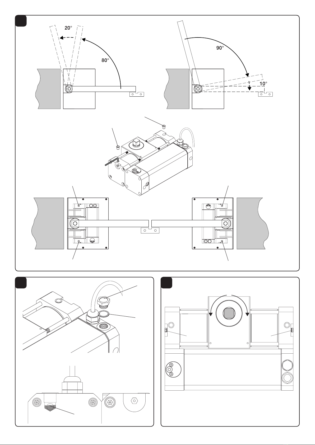
INSTALLAZIONE MOTORE
Prima di installare il motore tenere presente che:
Il motore può essere montato indiferentemente su anta
destra o sinistra.
Con riferimento alla Fig. 9 si denisce l’anta SX è quella
sinistra, l’anta DX è quella destra.
L’anta esegue un rallentamento idraulico di 10° in fase di
chiusura e di 20° in fase di apertura.
Predisposizone dei motori destro e sinistro.
Con riferimento alla Fig.11 per il motore sinistro:
1 Sbloccare idraulicamente il motore, svitando la vite di
sblocco V.
2 Ruotare completamente l’albero di uscita in senso orario
in modo da portarlo in posizione di chiusura.
Con riferimento alla Fig.12 per il motore destro :
1 Sbloccare idraulicamente il motore, svitando la vite di
sblocco V.
2 Ruotare completamente l’albero di uscita in senso antio-
rario in modo da portarlo in posizione di chiusura.
E’ possibile portare i motori in posizione di chiusura anche
elettricamente, collegandoli in modo provvisorio alla centra-
le di comando.
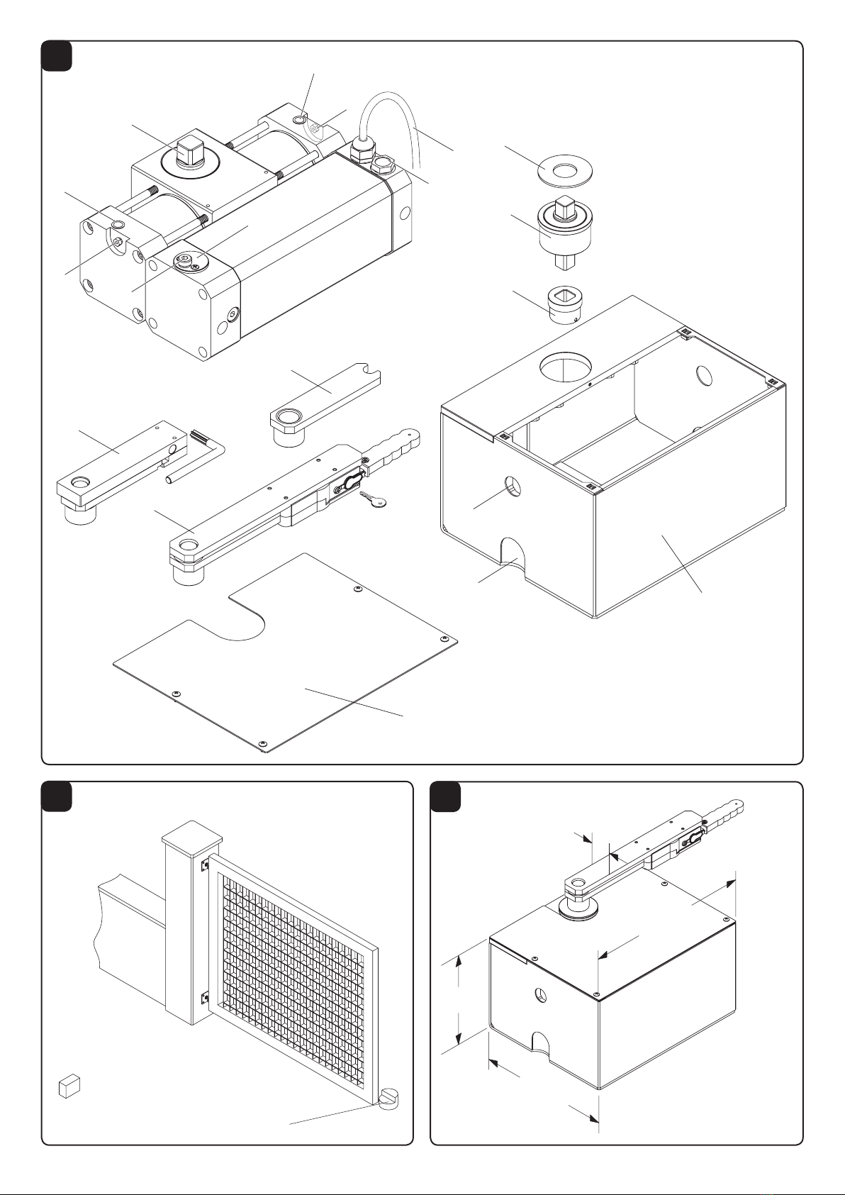
Inserimento dei motori nella cassa
Le operazioni sono le medesime per le due ante:
1 Portare l’anta in posizione di apertura in modo da rende-
re agevole l’accesso alla cassa.
2 Con riferimento all Fig.13, bloccare per mezzo del grano
G la bussola B sull’albero di trascinamento.
3 Inserire il motore all’interno della cassa.
Sul fondo della cassa è presente una guida che corri-
sponde alla scanalutara presente sul motore.
Facendo scorrere il motore su questa guida no all’arre-
sto, il motore si posiziona correttamente allinterno della
cassa.
4 Portare l’anta in posizione di completa chiusura sulla
battuta di arresto.
5 Allentare il grano G, la bussola scende sull’albero mo-
tore, collegando quest’ultimo all’albero di trascinamento
Fig.13b.
Può essere necessaria una piccola rotazione dell’albero
motore per il perfetto allineamento all’albero di trascina-
mento.
6 Fissare il grano G per bloccare la bussola nella posizione
di lavoro Fig.13c.
7 Riavvitare la vite di sblocco idraulico, se precedentemen-
te allentata.
COLLEGAMENTI ELETTRICI
Per il collegamento elettrico dell'automazione e per la regola-
zione delle modalità di funzionamento, consultate il manuale
istruzioni della centrale di comando.
Il motore è fornito con uno speciale cavo precablato a quat-
tro poli così contraddistinto:
NERO: MARCIA
GRIGIO: COMUNE
MARRONE: MARCIA
GIALLO/VERDE: GND
La Fig.16 riporta cablaggi da predisporre per una instal-
lazione standard. Prima di procedere con il passaggio dei
cavi vericate il tipo di cablaggio richiesto per gli accessori
effettivamente utilizzati.
Legenda componenti:
1 Motoriduttore SUBWAY
2 Fotocellule
3 Selettore a chiave o tastiera digitale
4 Lampeggiante
5 Antenna
6 Centrale di comando.
7 Elettroserratura *
*L'installazione dell'elettroserratura è indispensabile nei mo-
delli sprovvisti di blocco idraulico o comunque nelle ante di
lunghezza superiore a m. 2,5
IMPORTANTE: Tenere separati i cavi di potenza da
quelli ausiliari.
REGOLAZIONE FORZA DI SPINTA
L'attuatore è provvisto di un dispositivo antischiacciamen-
to (valvole by-pass) per la limitazione della forza di spinta
sull'anta in presenza di ostacolo. Una volta rimosso l'osta-
colo l'anta prosegue la sua corsa per il tempo di lavoro
impostato dalla centrale di comando.
Con Riferimento alla Fig.17:
- Rimuovere le due viti V
- Rimuovere il coperchio di protezione delle valvole
- Utilizzando una chiave a barra esagonale da 6 mm pro-
cedere alla regolazione della forza.
- Sono presenti due valvole regolabili una regola la spinta
in fase di apertura (Open), l'altra regola forza in fase di
chiusura (Close).
- A seconda del posizionamento del motore (SX-Sinistro/

10
11
DX-Destro) le valvole di apertura e chiusura risultano in-
vertite. Nella Fig.18 sono evidenziate le differenze tra due
le posizioni.
- Rotando la valvola in direzione + si aumenta la forza di
spinta dell'anta viceversa (direzione - ) la forza diminui-
sce.
ATTENZIONE! Questa regolazione inuisce sul grado di
sicurezza dell’automazione.
Vericare che la forza applicata sull’anta sia conforme
con quanto previsto dalle normative vigenti.
REGOLAZIONE RALLENTAMENTI
Tutti i modelli sono provvisti di regolazione del rallentamen-
to in fase di apertura e chiusura per un movimento più lento
dell’anta nella fase nale della manovra.
Nella Fig. 19 è rapresentato il comportamento dell’anta,
supponenedo per semplicità, l’utilizzo della corsa totale
disponibile (100°):
- Durante la fase di apertura l’anta inzia la manovra a piena
velocità e raggiunti gli 80° di apertura inzia la fase di rallen-
tamento che prosegue per altri 20°.
- Durante la fase di chiusura l’anta inzia la manovra a piena
velocità e, con 10° di anticipo rispetto alla battuta meccani-
ca di chiusura, inzia la fase di rallentamento.
Le regolazioni avvengono mediante due apposite viti di
regolazione protette da due tappi T (Fig.20).
Utilizzando una chiave a barra esagonale da 3mm:
- Allentare la vite per incrementare la velocità di rallenta-
mento.
- Fissare la vite per ridurre la velocità di rallentamento.
- A seconda del posizionamento del motore (SX-Sinistro/
DX-Destro) le viti di regolazione di apertura e chiusura
risultano invertite. Nella Fig.19 sono evidenziate le diffe-
renze tra due le posizioni.
Allentando al massimo la valvola si disattiva la funzione di
rallentamento.
Non forzare mai la valvola di regolazione.
RABBOCCO/SOSTITUZIONE OLIO
Tutti gli attuatori oleodinamici richiedono una verica perio-
dica del livello dell'olio.
Per il rabbocco è sufciente, dopo aver tolto alimentazione
di rete all'impianto, svitare il tappo evidenziato in Fig.20.
Sul fondo della sede della vite V (Fig.20) si deve vedere il
livello dell’olio, come rappresentato nella sezione (rif. L), se
così non fosse è necessario un rabbocco.
Utilizzare esclusivamente olio BIO OIL originale.
Vericare l’integrità della guarnizione G, nel caso risultasse
usurata o danneggiata provvedere alla sua sostituzione.
VITI DI SFIATO
Le due viti di sato (Fig.1 rif-3), consentono la fuoriscita
dell’aria dagli stantuf dell’attuatore.
L’attuatore viene fornito privo di aria nel circuito idraulico,
quindi normalmente non è richiesto nessun intervento.
Nel caso di manuntenzioni non ordinarie (smontaggio e
rimontaggio completo dell’attuatore) è necessario eseguire
l’operazione sato.
Per maggior praticità consigliamo di effettuare lo sato prima
di reinstallare l’attuatore, collegandolo provvisoriamente alla
centrale di comando:
- Dare un di apertura e portare a necorsa il martinetto e,
con il motore in spinta, aprire la vite di sato*.
- Fare uscire l’aria no alla comparsa di olio non emulsio-
nato.
- Fissare la vite di sato.
- Procedere in modo analogo nel senso di chiusura.
- Eseguire più volte tale operazione per entrambe le viti di
sato.
- Vercare il livello dell’olio, se necessario effettuare un
rabbocco.
* Per individuare le viti di sato di apertura e chiusura per le
versioni destra e sinistra, fate riferimento alla Fig.21:
Se il senso di rotazione è quello indicato dalla freccia A la
vite di sato su cui intervenire è la vite A, e viceversa, se il
senso di rotazione è quello indicato dalla freccia B la vite di
sato è la vite B.

10
11
EC Declaration of Conformity regarding machines
(Directive 89/392 CE, Annex II B) - No servicing
Manufacturer: AUTOMATISMI CAB Srl.
Address: Via della Tecnica,10 (z.i.) - 36010 Velo d’Astico (VI) (Italia)
We herewith declare that: the automatic system for swing gates, models SB.25AC - SB.35AC - SB.50..
• is intended to be incorporated into a machine or assembled together with other devices to form a machine in compliance with the
EC Directive 98/37, as amended;
• therefore, is not in every respect complying with this Directive;
• is complying with provisions set forth by the following other EC Directive:
EC Low voltage Directive (73/23/EEC, 93/68/EEC).
EC Directive of Electromagnetic Compatibility (89/336/EEC, 93/68/EEC)
Moreover, we herewith declare that the system shall not be put into service until the machine in which the same will be incorporated
or of which it will become a component, is acknowledged compliant with the EC Directive 98/73 and applicable national legislation
and a related declaration of conformity is drawn up. In other words, no servicing shall be carried out until the system under this
declaration does not form one single nal machine with other components.
Benincà Luigi, Legal responsible.
Velo d’Astico, 10/09/2008.
The product shall not be used for purposes or in ways
other than those for which the product is intended for and
as described in this manual. Incorrect uses can damage
the product and cause injuries and damages.
The company shall not be deemed responsible for the
non-compliance with a good manufacture technique of
gates as well as for any deformation, which might occur
during use.
Keep this manual for further use.
Qualied personnel, in compliance with regulations in force,
shall install the system.
Packaging must be kept out of reach of children, as it can
be hazardous. For disposal, packaging must be divided
the various types of waste (e.g. carton board, polystyrene)
in compliance with regulations in force.
The installer must supply all information on the automatic,
manual and emergency operation of the automatic system
and supply the end user with instructions for use.
WARNING
An omnipolar switch/section switch with remote
contact opening equal to, or higher than 3mm
must be provided on the power supply mains..
Make sure that before wiring an adequate differential
switch and an overcurrent protection is provided.
Pursuant to safety regulations in force, some types of in-
stallation require that the gate connection be earthed.
During installation, maintenance and repair, cut off power
supply before accessing to live parts.
Descriptions and gures in this manual are not binding.
While leaving the essential characteristics of the product
unchanged, the manufacturer reserves the right to modify
the same under the technical, design or commercial point
of view without necessarily update this manual.

12
13
GENERAL INFORMATION
The oil-hydraulic automatic system, single phase 230Vac
power supply, for swing gates, available in the following
versions:
SB.25 AC:
for leaves up to 2.5 m width, with lock in the opening and
closing phases
SB.35 AC:
For leaves up to 3.5 m width, with lock in the opening and
closing phases. For gate leaves wider than 2.5 m, the instal-
lation of an electric lock is required
SB.50:
For leaves up to 5m width, reversible model. An electric lock
is required.
SUBWAY is an oil-hydraulic system to be installed under-
ground, inside the special load-bearing box, Art. SB.FB. All
the models can be installed indifferently on right and left-hand
leaves. The motor performs a mechanical slowdown in both
opening and closing phases. Braking can be adjusted and,
if necessary, excluded.
The max stroke available is equal to 100°.
All CAB items are covered by an insurance policy for dam-
ages to objects or persons caused by manufacture defects.
This policy, however, requires that the machine is marked CE
and the components used for CAB are the original ones.
PRELIMINARY CHECKS
For a good operation of these automatic systems, the gate
shall full the following characteristics:
- good strength and stiffness.
- hinges shall have a minimum backlash and allow that the
manual operations be smooth and regular.
SPECIFICATIONS SB.25AC SB.35 AC SB.50
Power supply 230V 50Hz
Power 250 W
Absorbed current 1.2 A
Motor speed adjustment 1400 rpm
Cycles/hour (at 20°C) 55 45 35
Pump capacity 1 l/min 0.75 l/min 0.5 l/min
Max pressure 30 bar
Operation temperature -20°C / +55°C
Protection level IP 55
Max torque 400 Nm
Thermal protection 150°C
Noise < 70 db (a)
Capacitor 10 mF
Max gate leaf width 2.5 m 3.5 m 4 m 5 m
Max gate leaf weight 500 Kg 800 Kg 800 Kg 500 Kg
Angular speed 9°/s 6°/s 4.5°/s
90° opening speed (braking excluded) 10 s 15 s 20 s
Oil BIO OIL
Braking adjustment Hydraulic braking in opening/closing phase
Rotation angle of braking in closing phase 10° xed
Rotation angle of braking in opening phase Between 80° and 100°
Max usable rotation angle 100°
Type of bloc Hydraulic AC Hydraulic AC* Reversible
Electric lock No NO (leaf, 2.5m max) Yes
Weight 15 kg
- when closed, the gate leaves must match along the entire
height.
DESCRIPTION OF COMPONENTS
AND ACCESSORIES FIG.1
FIG.1
1 Output shaft
2 Protection cap for braking adjustment screw
3 Air bleed screw
4 Hydraulic release knob
5 Protection cap of by-pass valves
6 Oil cap
7 Power supply cable
8 Protection washer
9 Connection shaft
10 Connection bush
11 SB.BUSH plate without release for reversible versions
12 SB.SL release with standard lever
13 SB.KL release with customized key
14 Lid for SB.FB box
15 SB.FB self-bearing box
16 Duct for connecting cables
17 Water drain
MECHANIC STOPS - FIG.2
If they have not provided yet, closing and opening mechanic
stops must be provided, regardless from the type of opera-
tor installed.

12
13
The mechanic stop, in the closing phase (ref. C), is of key
importance due to the specic features of the oil-hydraulic
systems. See “lock maintenance” function in instructions
of the control unit.
DIMENSIONS
Fig.3: Box overall dimensions (mm)
Fig.4: Motor overall dimensions (mm)
Fig.5: Overall dimensions of the installation. The minimum
clearance between a rotation pin and the pier is 60 mm.
In the table of Fig.5, the minimum dimensions required for
the box and the lower prole of the door leaf are shown in
the various release versions. Dimension B is the clearance
between the release and the cover.
INSTALLATION
HOLE AND FITTING OF THE BOX
Dig a foundation hole with indicative dimensions shown in
Fig.6.
Make sure that the centre of the hole is aligned with the
rotation axis of the gate leaf (sectioned line).
Provide for an adequate water drain (Fig.1 ref.17), and pre-
pare the entrance of the cable duct (Fig.1 ref.16).
Water accumulating inside the box is however to be avoid-
ed. Possibly provide for a draining pipe connected to the
nearest drain.
Make sure that the rotating axis of the gate leaf (g.5 ref. R)
is perfectly vertical and that the box is perfectly at.
Fix the box with cement.
WELDING OF THE GATE LEAF
Carry out a careful welding of the rotation bracket onto the
entire prole of the gate leaf (Fig.7).
It is possible to avoid welding directly onto the gate leaf by
providing an adequate C bracket to be inserted between
the gate leaf and the rotation bracket (Fig.8).
In addition to the standard installation shown in Fig. 9, the
system can be also positioned as shown in Fig. 10, if the
gate leaves are installed internally.
MOTOR INSTALLATION
Before installing the motor, keep in mind that:
The motor can be assembled onto either right or left gate
leaf.
With reference to Fig. 9, a SX leaf is the leaf on the left,
while a DX leaf is the leaf on the right.
The gate leaf features a 10° hydraulic braking during clo-
sure and 20° hydraulic braking during opening.
Preparation of right and left motors.
With reference to Fig.11, for left motors:
1 Hydraulically release the motor by loosening the V re-
lease screw.
2 Completely turn the output shaft clockwise, until it reach-
es the closed position.
With reference to Fig.12, for right motors:
1 Hydraulically release the motor by loosening the V re-
lease screw.
2 Completely turn the output shaft anti-clockwise, until it
reaches the closed position.
The motors can be also electrically moved to the closed po-
sition by temporarily connecting them to the control unit.
Placing the motors in the box
The operations are similar for either gate leaves:
1 Open the gate leaf so as to facilitate the access to the
box.
2 By referring to Fig.13, lock the bush B on the drive shaft
by means of the grain G.
3 Place the motor inside the box.
On the bottom of the box, a track matching the grove on
the motor is provided.
The motor is correctly positioned inside the box by sliding
the motor onto this track until it clicks.
4 Close the gate leaf until it reaches the gate stop.
5 By loosening the grain G, the bush slides on the motor
shaft, thus connecting the motor shaft to the drive shaft,
Fig.13b.
To perfectly align the drive shaft, the motor shaft might
be slightly rotated.
6 Fix the grain G to lock the bush in the working position,
Fig.13c.
7 Tighten the hydraulic release screw, if previously backed
off.
WIRE CONNECTIONS
For the electric connections of the automatic system and to
adjust the operating modes, see the Operating Instructions
of the control unit.
The motor is supplied with a special pre-cabled, four pole
cable marked as follows:
BLACK: RUN
GREY: COMMON
BROWN: RUN
YELLOW/GREEN: EARTH
Fig.16 shows cabling to be provided for a standard instal-
lation. Before laying the cables, check the type of cabling
required for accessories actually used.
Key of components:
1 SUBWAY geared motor
2 Photocells
3 Key selector or digital keypad
4 Flashing warning beacon
5 Antenna
6 Control unit
7 Electric lock *
*The installation of the electric lock is mandatory in models
with hydraulic lock or in any case for gate leaves wider than
2.5 m
IMPORTANT: Keep the power cable detached from the
auxiliary ones.
ADJUSTMENT OF THE THRUST FORCE
The operator is equipped with an anti-crash device (by-
pass valves) for the regulation of the thrust on the gate leaf
when it hits an obstacle. Once the obstacle has been re-
moved, the gate carries on its movement for the operating
time preset by the control unit.
With reference to Fig.17:
- Remove the two screws V.
- Remove the protection cap of valves.
- By using a 6mm Allen key, proceed to the thrust regula-
tion.
- There are two adjustable valves, one regulates thrust in
the opening phase (Open), the other regulates thrust in
the closing phase (Close).
- According to the motor positioning (SX-Left/DX-Right)
the opening and closing valves are reversed. Fig. 18
shows the differences between the two positions.
- By turning the valve towards +, the thrust force of the

14
15
gate leaf is increased. By turning it the opposite direction
(- ) thrust decreases.
WARNING! This adjustment inuences the safety level of
the automatic system.
Make sure that the thrust applied to the gate leaf is
compliant with provisions set out by regulations in
force.
ADJUSTMENT OF BRAKING
All the models are provided with braking adjustment in both
opening and closing phases for a slower movement of the
gate leaf in the nal phase of operation.
Fig. 19 shows the gate leaf performance, assuming, for
simplicity purposes, that the total thrust available (100°)
is used:
- During the opening phase, the gate leaf starts the opera-
tion at full speed and, after reaching 80° opening, it starts
braking and continues for other 20°.
- During closure, the gate leaf starts operation at full speed
and, with 10° advance with respect to the mechanic stop,
it starts braking.
Adjustments are carried out by means of two special regu-
lation screws protected by two caps T (Fig.20).
By using a 3mm Allen key:
- Loosen the screw to increase braking.
- Fix the screw to reduce braking.
- According to the motor position (SX-Left/DX-Right) the
opening and closing adjustment screws are inverted.
Fig.19 shows the differences between two positions.
By loosening the valve to the maximum, braking is deacti-
vated.
Never exercise force on the adjustment valve.
TOPPING UP/REPLACEMENT OF OIL
All oil-hydraulic operators require a periodic review of the
oil level.
To top up oil, after cutting off the mains power supply, un-
screw the cap shown in Fig.20.
At the bottom of the housing of screw V (Fig.20), the oil level
should be seen, as shown in section L. If the oil level cannot
be seen, a topping up is required.
Use original BIO OIL only.
Check the good conditions of the gasket G. If it is worn or
damaged, replace it.
AIR BLEED SCREWS
Two air bleed screws (Fig.1 rif-3) allow for air bleeding from
the operator pistons.
The operator is supplied without air in the hydraulic circuit,
therefore, no intervention is usually required.
However, in the event of extraordinary maintenance op-
erations (total de-assembly and assembly of the operator),
bleeding should be carried out.
For practical reasons, we advise to bleed air before reinstall-
ing the operator, by temporarily connecting to the control
unit:
- Send an opening control, until the jack is against the limit
switches and, with motor on, open the air bleed screw *.
- Bleed air until not emulsioned oil appears.
- Fix the air bleed screw.
- Carry out the same procedure for the closing phase.
- Perform this operation more than once, for both air bleed
screws.
- Check oil level, if required top up with oil.
* To nd the opening and closing air bleed screws for the
right and left versions, refer to Fig.21:
if the rotation direction is the one indicated by arrow A, the air
bleed screw which must be used is screw A, and viceversa,
if the rotation direction is indicated by arrow B, the air bleed
screw which must be used is screw B.

14
15
EG-Konformitätserklärung für Maschinen
(Richtlinie 89/392 EG, Anhang II, Teil B) – Inbetriebsetzen verboten
Hersteller: AUTOMATISMI CAB Srl.
Adresse: Via della Tecnica,10 (z.i.) - 36010 Velo d’Astico (VI) (Italia
Wir erklären, dass: die Torantriebe für Flügeltore Modell SB.25AC - SB.35AC - SB.50..
• hergestellt worden ist, um in Maschinen eingebaut oder in Verbindung mit anderen Maschinen verwendet zu werden, wodurch
die Maschine laut EG-Richtlinie 98/37 als umgeändert gilt;
• die Automation entspricht daher nicht allen Punkten der Vorschriften dieser Richtlinie;
• sie entspricht folgenden EG-Richtlinien:
Niederspannungs-Richtlinie 73/23/EWG, 93/68/EWG.
Richtlinie über die elektromagnetische Verträglichkeit 89/336/EWG, 93/68/EWG.
Wir erklären zudem, dass die Maschine/Anlage in welche oder in Verbindung mit welcher die Automation installiert wird, nicht in
Betrieb gesetzt werden darf, bis sie identiziert und laut EG-Richtlinie 98/37 sowie laut den nationalen Gesetzen, die zur Umsetzung
der EG-Richtlinie erlassen wurden, als konform erklärt worden ist. Die hier genannte Automation muss daher mit der Maschine als
ein Ganzes als konform erklärt werden.
Benincà Luigi, Rechtsvertreter
Velo d’Astico, 10/09/2008.
Das Produkt darf nicht für andere Zwecke oder auf andere
Weise verwendet werden, als in der vorliegenden Anlei-
tung beschrieben. Ein ungeeigneter Gebrauch kann das
Produkt beschädigen und eine Gefahr für Personen und
Sachen darstellen.
Wir übernehmen keinerlei Haftung für Schäden, die sich aus
einer unsachgerechten Montage der Tore und aus daraus
folgenden Verformungen ergeben können.
Bewahren Sie dieses Handbuch für Nachschlagzwecke
auf.
Die Installation darf nur von qualizierten Fachleuten laut
den geltenden Vorschriften vorgenommen werden.
Das Verpackungsmaterial fern von Kindern halten, da es
eine potentielle Gefahr darstellt. Das Verpackungsmaterial
nicht ins Freie werfen, sondern je nach Sorte (z.B. Pappe,
Polystyrol) und laut den örtlich geltenden Vorschriften
entsorgen.
Der Installateur hat dem Benutzer alle Informationen über
den automatischen, manuellen Betrieb sowie den Not-
Betrieb der Automatik zusammen mit der Bedienungsan-
leitung zu liefern.
HINWEISE
Das Stromnetz muss mit einem allpoligen
Schalter bzw. Trennschalter ausgestat-
tet sein, dessen Kontakte einen Öffnun-
gsabstand gleich oder größer als 3 aufweisen..
Kontrollieren, ob der elektrischen Anlage ein
geeigneter Differentialschalter und ein Über-
spannungsschutzschalter vorgeschaltet sind.
Einige Installationstypologien verlangen den Anschluss
des Flügels an eine Erdungsanlage laut den geltenden
Sicherheitsnormen.
Während der Installation, der Wartung und der Reparatur,
die Anlage stromlos machen bevor an den elektrischen
Teilen gearbeitet wird.
Die in diesem Handbuch enthaltenen Beschreibungen
und Abbildungen sind nicht verbindlich. Ausgenommen
der Haupteigenschaften des Produkts, behält sich der Her-
steller das Recht vor eventuelle technische, konstruktive
oder kommerzielle Änderungen vorzunehmen ohne dass
er vorliegende Veröffentlichung auf den letzten Stand
bringen muss.

16
17
ALLGEMEINE INFORMATIONEN
Hydraulischer Torantrieb mit einphasiger Speisung 230Vac
für Flügeltore, in folgenden Ausführungen erhältlich:
SB.25 AC:
für Torügel bis zu 2,5 m mit Anschlag für Tor-Auf und Tor-
Zu;
SB.35 AC:
für Torügel bis zu 3,5 m mit Anschlag für Tor-Auf und Tor-
Zu; für Torügel länger als 2,5 m muss ein Elektroschloss
installiert werden
SB.50:
für Torügel bis zu 5 m, umkehrbar, muss ein Elektroschloss
installiert werden.
SUBWAY ist ein hydraulisch betriebener Torantrieb zur Un-
terur Montage in dem entsprechenden Gehäuse Art. SB.FB.
Alle Modelle können beliebig am rechten oder linken Torügel
montiert werden. Durch den Motor erfolgt hydraulisch eine
Geschwindigkeitsabnahme beim Öffnen und Schließen. Die
Geschwindigkeitsabnahme kann nach Wunsch eingestellt
oder auch ausgeschlossen werden.
Der maximal zulässige Hub beträgt 100°.
Alle CAB Produkte sind gegen Schäden oder Unfälle ver-
sichert, die sich aus Produktionsmängeln ergeben sollten;
dazu müssen sie jedoch die CE-Markierung tragen und aus-
schließlich mit CAB Originalteilen ausgestattet sein.
VORBEREITENDE PRÜFUNGEN
Für den einwandfreien Betrieb des Torantriebs, muss das
Tor nachstehende Eigenschaften aufweisen:
- es muss robust sein und eine gute Festigkeit aufweisen;
- die Scharniere dürfen wenig Spiel haben und müssen ie-
ßende, ungehinderte Bewegungen im manuellen Betrieb
gestatten;
TECHNISCHE DATEN SB.25AC SB.35 AC SB.50
Speisung 230V 50Hz
Leistung 250 W
Stromaufnahme 1.2 A
Drehgeschwindigkeit des Motors 1400 rpm
Zyklen/Stunden (bei 20°C) 55 45 35
Pumpenleistung 1 l/min 0.75 l/min 0.5 l/min
Druck max 30 bar
Betriebstemperatur -20°C / +55°C
Schutzklasse IP 55
Drehmoment max 400 Nm
Temperaturschutz 150°C
Geräuschpegel < 70 db (a)
Kondensator 10 mF
Max. Torügellänge 2.5 m 3.5 m 4 m 5 m
Max. Torügelgewicht 500 Kg 800 Kg 800 Kg 500 Kg
Winkelgeschwindigkeit 9°/s 6°/s 4.5°/s
Öffnungsdauer 90°
(Geschwindigkeitsabnahme nicht inbegriffen) 10 s 15 s 20 s
Öl BIO OIL
Bremskraftregelung Hydraulische Geschwindigkeitsabnahme bei Öffnen/Schließen
Geschwindigkeitsabnahme beim Schließen ab
10° (fest Einstellung)
Geschwindigkeitsabnahme beim Öffnen zwischen 80° und 100°
Max. nutzbarer Drehbereich 100°
Blockierungsart Hydraulisch AC Hydraulisch AC* Umkehrbar
Elektroschloss Nein Nein (Torügel max 2,5m) Ja
Gewicht 15 kg
- im geschlossenen Zustand müssen die Torügel entlang
der gesamten Höhe miteinander übereinstimmen.
BESCHREIBUNG DER BESTANDTEILE UND
DES ZUBEHÖRS ABB. 1
1 Ausgangswelle
2 Verschluss Stellschraube Geschwindigkeitsabnahme
3 Entlüftungsschraube
4 Drehknopf hydraulische Entriegelung
5 Verschluss Bypass Ventil
6 Ölverschluss
7 Stromkabel
8 Schutzscheibe
9 Anschlusswelle
10 Verbindungsbuchse
11 SB.BUSH Platte ohne Entriegelung für umkehrbare Aus-
führungen
12 SB.SL Entriegelung mit Standardhebel
13 SB.KL Entriegelung mit kundenspezischem Schlüssel.
14 Gehäusedeckel SB.FB
15 Gehäuse SB.FB
16 Durchgang für Verbindungskabel
17 Wasserablass
MECHANISCHE ANSCHLÄGE ABB. 2
Falls solche Anschläge nicht vorhanden sein sollten, müssen
sie für das Schließen und Öffnen unabhängig vom installier-
ten Aktuator vorgesehen werden.
Der mechanische Anschlag für Tor-Zu (Ref. C) ist im Hin-

16
17
blick auf die Eigenschaften der hydraulischen Aktuatoren
besonders wichtig. Siehe Funktion „Blockierung“ in den
Anweisungen der Steuereinheit.
MASSE
Abb. 3: Außenmaße des Gehäuses (mm)
Abb. 4: Außenmaße des Motors (mm)
Abb. 5: Installationsmaße. Der Mindestabstand zwischen
Drehstift und Säule beträgt 60 mm
In der Tabelle der Abb. 5 sind die Mindestmaße aufgeführt,
die zwischen Gehäuse und dem unteren Flügelprol bei
den unterschiedlichen Entriegelungen eingehalten werden
müssen. Das Maß B bezieht sich auf den freien Abstand
zwischen Entriegelung und Abdeckung.
INSTALLATION
UNTERFLUREINBAU DES GEHÄUSES
Eine Ausschachtung mit den Maßen der Abb. 6 vorberei-
ten.
Die Schachtmitte muss mit der Drehachse des Flügels lot-
rech verlaufen (gestrichelte Linie).
Für das Wasser muss eine geeignete Drainage (Abb. 1, Ref.
17) und für die Kabel muss ein Schutzrohr vorgesehen wer-
den (Abb., Ref. 16).
Vermeiden Sie auf jeden Fall, dass sich Wasser im Gehäu-
se ansammelt und verlegen Sie ein Drainagerohr bis zum
nächsten Abwasserkanal.
Stellen sie sicher dass die Drehachse des Torügels (Abb.
5, Ref. R) lotrecht und das Gehäuse einwandfrei nivelliert
ist.
Das Fundament muss für das Gehäuse ausgehärtet sein.
SCHWEISSARBEITEN AM TORFLÜGEL
Den Drehstift entlang des gesamten Flügelprols anschwei-
ßen (Abb. 7).
Um die Schweißarbeiten nicht direkt am Torügel vorzu-
nehmen, kann ein C-förmiger Bügel zwischen Torügel und
Drehstift (Abb. 8) eingesetzt werden.
Abgesehen von der Standardmontage, wie sie in Abb. 9
dargestellt ist, besteht eine wietere Montagemöglichkeit
wie in Abb. 10 dargestellten, für den Fall dass die Torügel
nach Innen montiert sind.
MOTOR INSTALLIEREN
Vor der Installation des Motors, beachten Sie bitte Folgen-
des:
Der Motor kann sowohl am rechten als auch am linken
Torügel montiert werden.
Bezugnehmend auf Abb. 9: „SX“ und „DX“ bezeichnen
bzw. den linken und den rechten Torügel.
Die hydraulisch gesteuerte Torügelgeschwindigkeit nim-
mt beim Schließen um 10° und beim Öffnen um 20° ab.
Vorbereitung des rechten und linken Motors.
Bezugnehmend auf Abb. 11, linker Motor:
1 Den Motor hydraulisch durch abschrauben der Siche-
rungsschraube V entriegeln.
2 Die Ausgangswelle im Uhrzeigersinn bis zum Anschlag
bzw. bis in die geschlossene Position drehen.
Bezugnehmend auf Abb. 12, rechter Motor:
1 Den Motor hydraulisch durch abschrauben der Siche-
rungsschraube V entriegeln.
2 Die Ausgangswelle gegen den Uhrzeigersinn bis zum
Anschlag bzw. bis in die geschlossene Position drehen.
Die Motoren können auch elektrisch gesteuert in die ge-
schlossene Position gefahren werden, wenn sie vorüberge-
hend an die Steuereinheit geschlossen werden.
Motoren in das Gehäuse einbauen.
Die Vorgehensweise ist für beide Torügel dieselbe:
1 Den Torügel vollständig öffnen, um das Gehäuse leicht
zugänglich zu machen.
2 Bezugnehmend auf Abb. 13, mithilfe des Stifts G, die
Buchse B an der Antriebswelle blockieren.
3 Den Motor in das Gehäuse einsetzen.
Am Gehäuseboden bendet sich eine Schiene, die mit
der Nut des Motors übereinstimmt.
Schieben Sie den Motor auf dieser Schiene bis zum An-
schlag so dass der Motor richtig im Gehäuse positioniert
wird.
4 Den Torügel vollständig, bis zum Anschlag schließen.
5 Den Stift G lockern; dadurch sinkt di Buchse bis auf die
Motorenwelle so dass die Verbindung mit der Antriebs-
welle hergestellt wird - Abb. 13b.
Zur genauen Ausrichtung der beiden Wellen, die Moto-
renwelle etwas bewegen.
6 Den Stift G befestigen um die Buchse in der entgültigen
Betriebsposition zu sichern - Abb. 13c.
7 Hydraulische Entriegelungsschraube wieder festziehen.
ELEKTRISCHE ANSCHLÜSSE
Um die Automatik elektrisch anzuschließen und den Be-
triebsmodus einzustellen, siehe Gebrauchsanweisungen
der Steuereinheit.
Der Motor ist mit einem 4-poligen Kabel ausgestattet:
SCHWARZ: BETRIEB
GRAU: GEMEIN
BRAUN: BETRIEB
GELB/GRÜN: GND
Die Abb. 16 zeigt die Verkabelungen wie sie für eine Standar-
dinstallation benötigt werden. Bevor die Kabel durchgeführt
werden, kontrollieren ob der Kabeltyp für das verwendete
Zubehör geeignet ist.
Erläuterung der Komponenten:
1 Getriebemotor SUBWAY
2 Fotozellen
3 Schlüsselwähler oder digitale Tastatur
4 Blinkleuchte
5 Antenne
6 Steuereinheit
7 Elektroschloss*
* Ein Elektroschloss muss bei den Modellen mit hydraulischer
Blockierung und für Flügelbreiten von über 2,5 m zwingend
installiert werden.
WICHTIG: Stromkabel von den Hilfskabeln getrennt
verlegen.

18
19
DRUCKKRAFTEINSTELLUNG
Der Aktuator ist mit einer Sicherheitsvorrichtung gegen
Quetschgefahr (Bypass Ventil) ausgestattet, die die Druck-
kraft des Torügels in Gegenwart eines Hindernisses be-
schränkt. Nachdem das Hindernis entfernt worden ist, be-
wegt sich der Torügel weiter, bis die an der Steuereinheit
eingestellte Betriebszeit abgelaufen ist.
Bezugnehmend auf Abb. 17:
- Die beiden Schrauben V abschrauben
- Den Verschluss der Ventile entfernen
- Mit einem Sechskantsteckschlüssel zu 6 mm die Kraft
einstellen.
- Es sind zwei einstellbare Ventile vorhanden: Das erste
Ventil regelt den Druck beim Öffnen (Open), das andere
den Druck beim Schließen (Close).
- Je nach Motorposition (SX-links/DX-rechts) sind die Öff-
nungs- und Schließventile vertauscht. Die Abb. 18 zeigt
den Unterschied zwischen den beiden Positionen.
- Dreht man das Ventil in Richtung +, nimmt die Kraft zu;
dreht man es in die umgekehrte Richtung (-), nimmt die
Kraft ab.
ACHTUNG! Diese Einstellung hat Einuss auf die Siche-
rheit des Torantriebs.
Die für den Torügel angewendete Kraft muss den gel-
tenden Vorschriften entsprechen.
REGELUNG DER GESCHWINDIGKEITSABNAHMEN
Bei allen Modellen kann die Geschwindigkeitsabnahme
beim Öffnen und Schließen eingestellt werden, so dass sich
der Torügel gegen Ende langsamer bewegt.
Die Abb. 19 zeigt die Betriebsweise des Torügels. Der Ein-
fachheit halber bezieht sich das Beispiel auf den gesamten
Hub (100°):
- Beim Öffnen bewegt sich der Torügel bei maximaler
Geschwindigkeit. Wenn er einen Winkel von 80° erreicht,
nimmt die Geschwindigkeit für die restlichen 20° ab.
- Beim Schließen bewegt sich der Torügel bei maximaler
Geschwindigkeit. 10° vor dem mechanischen Anschlag,
nimmt die Geschwindigkeit ab.
Die Einstellung erfolgt über die beiden Stellschrauben die
durch einen Verschluss T geschützt sind (Abb. 20).
Mit einem Sechskantsteckschlüssel zu 3 mm:
- Die Schraube lockern, um die Geschwindigkeitsabnah-
me zu erhöhen.
- Die Schraube zudrehen, um die Geschwindigkeitsabnah-
me zu verringern.
- Je nach Motorposition (SX-links/DX-rechts) sind die
Stellschrauben für Öffnen und Schließen vertauscht. Die
Abb. 19 zeigt den Unterschied zwischen den beiden Po-
sitionen.
Wird das Ventil bis zum Endanschlag gelockert, wird die
Funktion der Geschwindigkeitsabnahme deaktiviert.
Auf das Regelventil niemals Kraft ausüben.
ÖL NACHFÜLLEN/AUSWECHSELN
An allen hydraulischen Aktuatoren, muss der Ölstand in
regelmäßigen Zeitabständen kontrolliert werden.
Um Öl nachzufüllen, genügt es die Anlage stromlos zu ma-
chen und den Ölverschluss (Abb. 20) abzuschrauben.
Im Inneren des Sitzes der Schraube V (Abb. 20) muss das
Öl sichtbar sein (siehe Ref. L). Sollte dies nicht der Fall sein,
muss Öl nachgefüllt werden.
Verwenden Sie dazu ausschließlich das original BIO OIL.
Prüfen Sie den Zustand der Dichtung G. Falls sie verschleißt
oder beschädigt ist, wechseln Sie diese aus.
ENTLÜFTUNGSSCHRAUBEN
Die beiden Entlüftungsschrauben (Abb. 1, Ref. 3) gestatten
es die Kolben des Aktuators zu entlüften.
Der hydraulische Aktuatorkreislauf enthält i.d.R. keine Luft,
weshalb keine Wartung vorgesehen ist.
Wenn aber außerordentliche Wartungsarbeiten vorgenom-
men werden (Aktuator abmontieren und erneut montieren)
muss der Kreislauf entlüftet werden.
Es ist empfehlenswert den Kreislauf vor der erneuten Mon-
tage des Aktuators zu entlüften und diesen dazu vorüber-
gehend an die Steuereinheit zu schließen:
- Einen Öffnungsimpuls geben und die Winde bis zum En-
danschlag führen. Wenn sich der Motor im Druckbetrieb
bendet, das Entlüftungsventil öffnen*.
- Das Entlüftungsventil erst wieder schließen, wenn das Öl
blasenfrei herausießt.
- Entlüftungsschraube wieder festschrauben.
- Denselben Vorgang für die Schließfunktion vornehmen.
- Diesen Vorgang mehrmals an beiden Entlüftungsschrau-
ben wiederholen.
- Den Ölstand prüfen und falls erforderlich, Öl nachfüllen.
* Um die Entlüftungsschrauben für das Öffnen und Schließen
an den rechten und linken Ausführungen zu identizieren,
beziehen Sie sich bitte auf Abb. 21.
Wenn die Drehrichtung dem Pfeil A entspricht, muss die
Entlüftungsschraube A betätigt werden; wenn die Drehri-
chtung dem Pfeil B entspricht, muss die Entlüftungsschraube
B betätigt werden.

18
19
Déclaration CE de conformité pour machines
(Directive 89/392 CE, Annexe II, partie B) – Interdiction de mise en service
Fabricant: AUTOMATISMI CAB Srl
Adresse: Via della Tecnica,10 (z.i.) - 36010 Velo d’Astico (VI) (Italia)
Déclare que:l’automatisme pour portails à battants modèle SB.25AC - SB.35AC - SB.50.
• est conçu pour être incorporé dans une machine ou pour être assemblé avec d’autres machines à n que le tout puisse constituer
une machine considérée par la Directive CE, comme modiée;
• donc elle n’est pas conforme point pour point à tous les termes de cette Directive;
• elle satisfait les conditions des autres Directives CE ci-dessous:
Directive basse tension 73/23/CEE, 93/68/CEE.
Directive compatibilité électromagnétique 89/336/CEE, 93/68/CEE.
et de plus le fabricant déclare qu’il est formellement interdit de mettre en service l’appareillage jusqu’à ce que la machine dans
laquelle il sera incorporé ou dont il deviendra une partie composante, n’ait été identiée et déclaré conforme à la Directive 98/37
CE et à sa transposition dans la législation nationale, c’est-à-dire jusqu’à ce que la machine dont à la présente déclaration ne forme
pas un complexe unique avec la machine nale.
Benincà Luigi, Responsable légal.
Velo d’Astico, 10/09/2008.
Il est interdit d’utiliser ce produit pour l’utilisation du pro-
duit ou avec des nalités ou modalités non prévues par le
présent manuel. Toute autre utilisation pourrait compro-
mettre l’intégrité du produit et présenter un danger pour
les personnes ou pour les biens.
Le fabricant décline toute responsabilité en cas d’utilisation
impropre ou d’inobservation de la bonne technique dans la
construction des portails, ainsi que de toute déformation
qui pourrait avoir lieu lors de son utilisation.
Toujours conserver la notice pour toute autre consultation
future.
L’installation doit être faite uniquement par un personnel
qualié dans le respect total des normes en vigueur.
Tenir à l’écart des enfants tous les matériaux d’emballage
car ils représentent une source potentielle de danger. Ne
pas disperser les matériaux d’emballage dans l’environne-
ment, mais trier selon les différentes typologies (i.e. carton,
polystyrène) et les traiter selon les normes locales.
L’installateur doit fournir toutes les informations relatives
au fonctionnement automatique, au déverrouillage d’ur-
gence de l’automatisme, et livrer à l’utilisateur les modes
d’emploi.
REGLES DE SECURITE’
Prévoir sur le réseau de l’alimentation un interrup-
teur / sectionneur omnipolaire avec distance d’ou-
verture des contacts égale ou supérieure à 3 mm..
Vérier la présence en amont de l’installation électrique
d’un interrupteur différentiel et d’une protection de sur-
courant adéquats.
Certains types d’installation requièrent le branchement du
vantail à une installation de mise à terre satisfaisant les
normes de sécurité e vigueur.
Avant toute intervention, d’installation, réparation et main-
tien, couper l’alimentation avant d’accéder aux parties
électriques.
Les descriptions et les illustrations présentées dans ce
manuel ne sont pas contraignantes. En laissant inaltérées
les caractéristiques essentielles du produit, le fabricant se
réserve le droit d’apporter toute modication à caractère
technique, de construction ou commerciale sans s’engager
à revoir la cette publication.

20
21
CARACTÉRISTIQUES GÉNÉRALES
Automation oléo-dynamique avec alimentation monophasé
230 Vac pour portails battants, disponibles dans les versions
suivantes:
SB.25 AC:
pour vantaux jusqu’à 2,5 m avec blocage en phase d’ouver-
ture et en phase de fermeture
SB.35 AC:
pour vantaux jusqu’à 3,5 m avec blocage en phase d’ouver-
ture et de fermeture, pour vantaux qui dépassent 2,5m il faut
installer la serrure électrique
SB.50:
pour vantaux jusqu’à 5m, réversibles, la serrure électrique
sera nécessaire.
SUBWAY est un automatisme oléo-dynamique à installer
en position souterraine à l’intérieur du caisson spécial selon
art. SB.FB. Tous les modèles peuvent être installés indiffé-
remment sur le vantail de droite et de gauche. Le moteur
suit un ralentissement hydraulique en phase d’ouverture et
de fermeture. Le ralentissement peut être réglé et, si néces-
saire, exclu.
La course maxi disponible est égale à 100°.
Tous les produits CAB sont couverts par une police d’as-
surance qui répond à d’éventuels dommages à objets ou
personnes provoqués par des défauts de fabrications, mais
à condition que la «machine» porte le marquage CE et les
composants utilisées sont tous originels CAB.
CONTRÔLES PRELIMINAIRES
Pour un bon fonctionnement des automatismes en objet,
le portail à automatiser devra posséder les caractéristiques
suivantes:
- bonne robustesse et rigidité.
DONNÉES TECHNIQUES SB.25AC SB.35 AC SB.50
Alimentation 230V 50Hz
Puissance 250 W
Puissance absorbée 1.2 A
Vitesse rotation moteur 1400 tours/min
Cycles/heure (à 20°C) 55 45 35
Débit de la pompe 1 l/min 0.75 l/min 0.5 l/min
Pression max 30 bar
Température de fonctionnement -20°C / +55°C
Degré de protection IP 55
Couple max 400 Nm
Protection thermique 150°C
Bruyance < 70 db (a)
Condensateur 10 mF
Longueur vantail max 2.5 m 3.5 m 4 m 5 m
Poids vantail max 500 Kg 800 Kg 800 Kg 500 Kg
Vitesse angulaire 9°/s 6°/s 4.5°/s
Temps d’ouverture 90° (sauf ralentissement) 10 s 15 s 20 s
Huile BIO OIL
Réglage du freinage Ralentissement hydraulique en ouvre-ferme
Angle de rotation freinage fermeture Fixe 10°
Angle de rotation freinage ouverture Compris entre 80°÷100°
Angle de rotation freinage max utilisable 100°
Typologie de blocage Hydraulique AC Hydraulique AC* Réversible
Serrure électrique No
NO (vantail max 2,5m)
Oui
Poids 15 kg
- les charnières doivent présenter des serrages maximales
et permettre des manœuvres manuelles douces et régu-
lières.
- en position de fermeture les vantaux doivent s’ajuster entre
eux tout le long de leur hauteur.
DESCRIPTION DES COMPOSANTS
ET ACCESSOIRES
FIG.1
1 Arbre de sortie
2 Bouchon de protection vis de réglage ralentissement
3 Vis de purge
4 Pommeau de déblocage hydraulique
5 Bouchon de protection des soupapes by-pass
6 Bouchon d’huile
7 Conducteur d’alimentation
8 Rondelle de protection
9 Arbre de raccordement
10 Douille de raccordement
11 SB.BUSH plaque sans déblocage pour les
versions réversibles
12 SB.SL déblocage avec levier standard
13 SB.KL déblocage avec clé personnalisée
14 Couvercle caisson SB.FB
15 Caisson porteur SB.FB
16 Passage pour câbles de raccordement
17 Drainage d’eau
This manual suits for next models
2
Table of contents
Languages: