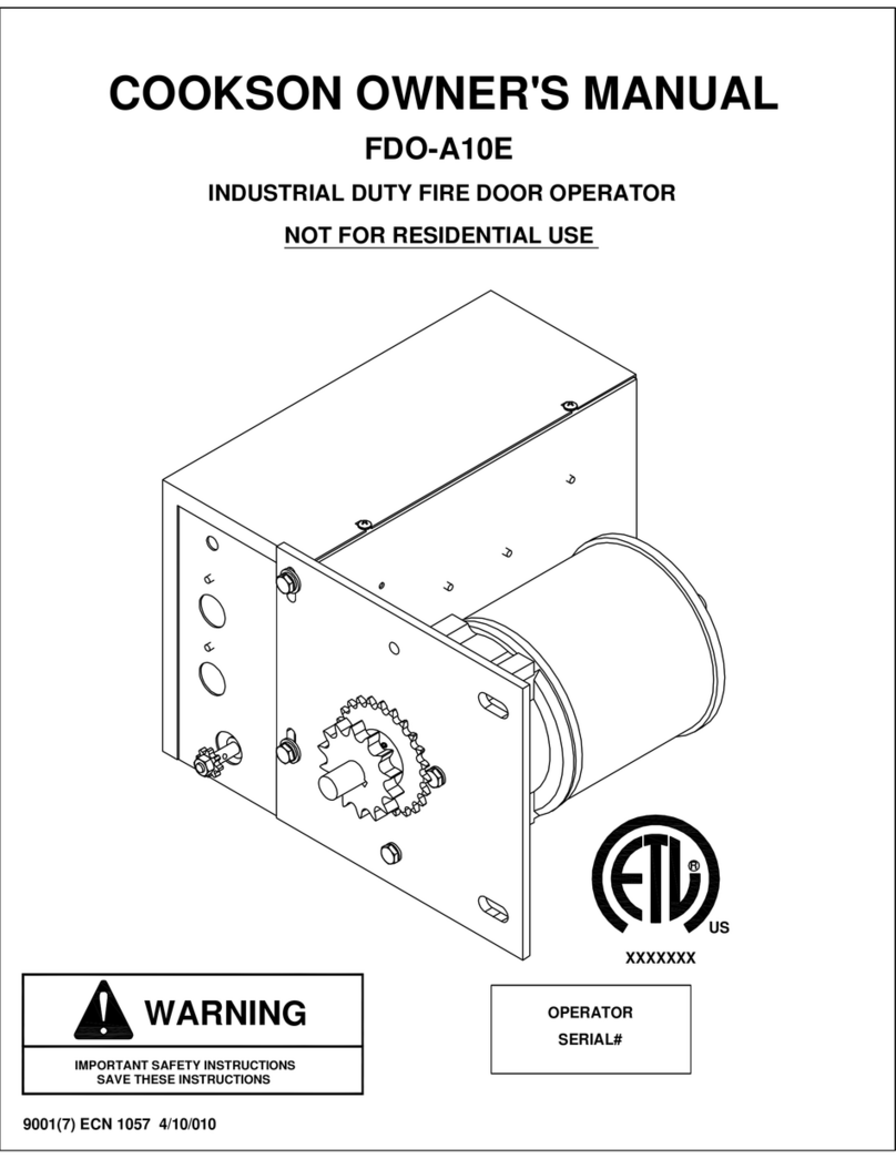
Cookson FDO-A10 User manual

COOKSON OWNER'S MANUAL
INDUSTRIAL DUTY FIRE DOOR OPERATOR
FDO-A10
9001.DWG ECN 0959 REV 4
3040233
R
L
I
S
T
E
D
US
CONTROL PANEL
SERIAL# SERIAL#
OPERATOR

SPECIFICATIONS
MOTOR ELECTRICAL
TYPE:.......................................INTERMITTENT
HORSEPOWER:......................1/8 H.P.
VOLTAGE:...............................115 SINGLE PHASE
CURRENT:...............................2.5 AMP
TRANSFORMER:.....................24VAC, 40VA
CONTROL STATION:..............NEMA 1 3 BUTTON STATION
OPEN/CLOSE/STOP
WIRING TYPE:.........................B2 (STANDARD)
LIMIT ADJUST:........................LINEAR DRIVEN, FULLY
ADJUSTABLE SCREW TYPE CAMS
MECHANICAL
DRIVE REDUCTION:..............43:1 REDUCTION IN LINE
GEAR REDUCED MOTOR
OUTPUT SHAFT SPEED:......29 R.P.M.
DOOR SPEED:........................12" PER SECOND
BRAKE:...................................SOLENOID ACTUATED
DISC BRAKE
DIMENSIONS
MOUNTING DIMENSIONS
2

THEORY OF OPERATION
GENERAL DESCRIPTION:
The Fire Door Operator, FDO-A10, is an integrated fire door control system. It is designed to
interface with a normally closed (NC) alarm system to control the operation of a fire door.
1. FDO-A10 MODEL:
1.1 UNIT HAS AC POWER & NO ALARM CONDITION:
NOTICE
THIS OPERATOR IS NOT A FIRE ALARM SYSTEM.
IT CAN NOT DETECT A FIRE CONDITION
The B2 control station is used to operate the door
electrically.
Activation of the safety edge while door is closing
will cause it to reverse to full open limit.
1.2 ALARM CONDITION W/ AC POWER:
Door begins powered closure (No Delay)
If obstruction is encountered, door will reverse to open
position and attempt closure again. The door will cycle
up to 3 attempts before resting on the obstruction. If the
obstruction is removed the door will continue to the fully
closed position. (At any time the open button will raise the
door to the fully open position and begin closing immediately).
(The cycle timer will not reset).
1.3 UNIT HAS NO AC POWER:
The unit is not functional and the brake is released.
Door will close without delay.
3
The control station is the standard B2 wiring.
TO REDUCE THE RISK OF INJURY TO PERSONS,
USE THIS OPERATOR ONLY WITH ROLLING DOORS.
WARNING

OPERATOR MOUNTING
Before your operator is installed, be sure the door has been properly aligned and is working
smoothly. Refer to the Door Installation Instructions for proper operator installation. This
motor operator is an integral part of the door system. The motor operator and governor (if
provided) controls door descent speed under power outage conditions.
WARNING
THE FIREDOOR CONTROLLER WILL NOT CLOSE A BALANCED DOOR IN THE ABSENCE OF AC
POWER. THE DOOR SYSTEM MUST BE ABLE TO GENERATE A MINIMUM BACKDRIVING TORQUE
OF 50 IN/LBS. AT THE OPERATOR OUTPUT SHAFT. STICKING OR BINDING DOORS MUST BE
REPAIRED. DOORS, DOOR SPRINGS, BRACKETS AND THEIR HARDWARE MAY BE UNDER
EXTREME TENSION AND CAUSE SERIOUS PERSONAL INJURY. CALL A PROFESSIONAL DOOR
SERVICEMAN TO MOVE OR ADJUST DOOR SPRINGS OR HARDWARE.
1) Find a convenient location within 25' of door to mount controller.
2) Mount controller with (4) provided fasteners.
WALL MOUNTED CONTROLLER MOUNTING
1) Wire controller to motor limit switch enclosure per wiring diagram. Use 16 GA copper
WALL MOUNTED CONTROLLER WIRING
conductors.
DO NOT CONNECT POWER TO CONTROLLER AT THIS TIME
OPERATOR AND CONTROLLER MUST BE WIRED IN ACCORDANCE WITH LOCAL
ELECTRICAL CODES.
ALARM INPUTS
1) Alarm inputs (Terminal A1 & A2) are used for electronic alarm devices such as smoke detectors
or similar alarm systems. The alarm activation circuit must be normally closed (NC) and must
open in an alarm condition.
AN ALARM DEVICE MUST BE CONNECTED TO THE ALARM INPUT BEFORE
INSTALLATION IS COMPLETE.
DURING INITIAL SETUP MAKE SURE A CLOSED CIRCUIT IS CONNECTED TO ALARM
INPUT. FAILURE TO DO SO MAY CAUSE THE OPERATOR TO ACTIVATE SUDDENLY
WITHOUT WARNING.
4

DO NOT INSTALL ANY WIRING OR ATTEMPT TO RUN THE OPERATOR WITHOUT
BEFORE INSTALLING POWER WIRING OR CONTROL STATIONS BE SURE TO FOLLOW
INSTALL POWER WIRING & CONTROL STATION
CONSULTING THE WIRING DIAGRAM. INSTALL THE REVERSING EDGE BEFORE
ALL SPECIFICATIONS AND WARNINGS DESCRIBED BELOW. FAILURE TO DO SO MAY
RESULT IN SEVERE INJURY TO PERSONS AND/OR DAMAGE TO OPERATOR.
PROCEEDING WITH THE CONTROL STATION INSTALLATION.
IMPORTANT SAFETY NOTES
THE DOOR. FAILURE TO INSTALL A REVERSING EDGE UNDER THESE CIRCUMSTANCES
ACTIVATE THE DOOR, A REVERSING EDGE MUST BE INSTALLED ON THE BOTTOM OF
VISIBLE, OR IF ANY DEVICE OTHER THAN THE CONTROL STATION IS USED TO
THE OPERATOR. IF CONTROL STATION CANNOT BE INSTALLED WHERE DOOR IS
DOOR AND IT'S HARDWARE. DO NOT INSTALL CONTROL STATION DIRECTLY BENEATH
INSTALL THE CONTROL STATION WHERE THE DOOR IS VISIBLE, BUT AWAY FROM THE
MAY RESULT IN SERIOUS INJURY OR DEATH TO PERSONS TRAPPED BENEATH DOOR.
FUNCTIONAL, INSTALL AN INTERLOCK SWITCH.
SECURE LOCK(S) IN "OPEN" POSITION. IF THE DOOR LOCK NEEDS TO REMAIN
TO AVOID DAMAGE TO DOOR AND OPERATOR, MAKE ALL DOOR LOCKS INOPERATIVE.
OUT THE POWER VIA THE MAIN DISCONNECT SWITCH. UPON COMPLETION OF
NOT BE PERFORMED UNTIL DISCONNECTING THE ELECTRICAL POWER AND LOCKING
ANY MAINTENANCE TO THE OPERATOR OR IN THE AREA NEAR THE OPERATOR MUST
MAINTENANCE THE AREA MUST BE CLEARED AND SECURED. AT THAT TIME THE UNIT
MAY BE RETURNED TO SERVICE.
OF ADEQUATE CAPACITY. ALL ELECTRICAL CONNECTIONS MUST BE MADE BY A
ELECTRICAL CODES. NOTE: THE OPERATOR SHOULD BE ON A SEPERATE FUSED LINE
PROPERLY GROUNDED AND PERMANENTLY WIRED IN ACCORDANCE WITH LOCAL
DISCONNECT POWER AT THE FUSE BOX BEFORE PROCEEDING. OPERATOR MUST BE
QUALIFIED INDIVIDUAL.
AND SERIOUS INJURY.
FAILURE TO PROPERLY GROUND THIS UNIT COULD RESULT IN ELECTRIC SHOCK
ELECTRICAL BOX FOR CONNECTION OF THE POWER SUPPLY GROUND WIRE.
THE UNIT MUST BE PROPERLY GROUNDED. A GROUND SCREW IS SUPPLIED IN THE
1) Wire power and control stations to motor controller per control connection diagrams.
5
ENTRAPMENT PROTECTION ACCESSORIES
THE OPERATOR MUST BE USED ON A DOOR WITH A SENSING EDGE
SENSING EDGES: All types of sensing edges with a normally open (N.O.) output are compatible
with your operator. The operator has been pre-wired to accept connection of a reversing edge
device. Connect the normally open contacts to terminals 10 & 11 in the wall mounted controller
The auxiliary limit switch will deactivate the safety device during the last few inches in the door's
downward travel. NOTE: For wiring connections refer to wiring diagram.
IMPORTANT NOTES:
1) Proceed with Limit Switch Adjustments before making any sensing edge wiring connections
to operator as described below.
2) Verify that alarm terminal A1 & A2 are connected to a normally closed circuit before applying
power to operator controller.

LIMIT SWITCH ADJUSTMENT
MAKE SURE THE LIMIT NUTS ARE POSITIONED BETWEEN THE LIMIT SWITCH ACTUATORS
BEFORE PROCEEDING WITH ADJUSTMENTS. MAKE SURE OPENING AND THE AREA NEAR
DOOR/OPERATOR AND MECHANISMS ARE CLEAR OF OBSTRUCTIONS AND PERSONNEL.
1) To adjust limit nuts depress retaining plate to allow nut to spin freely. After adjustment,
ELECTRIC POWER BEFORE MANUALLY MOVING LIMIT NUTS.
TO AVOID SERIOUS PERSONAL INJURY OR DEATH FROM ELECTROCUTION, DISCONNECT
WARNING
release plate and ensure it seats fully in slots of both nuts.
2) To increase door travel, spin nut away from actuator. To decrease door travel, spin limit
nut toward actuator.
3) Adjust open limit nut so that door will stop in open position with the bottom of the door
even with top of door opening.
4) Repeat Steps 1 and 2 for close cycle. Adjust close limit nut so that actuator is engaged
as door fully seats at the floor.
5) Connect sensing edge to controller terminals 10 & 11 and test operation.
6

7
ADJUSTING DOOR SPRING BALANCE
1) Tension door as per Door Installation Instructions.
WARNING
IF PROPER DOOR BALANCE CANNOT BE OBTAINED, STOP IMMEDIATELY AND CALL
TECHNICAL SUPPORT.
4) If door closes too rapidly follow Step 3 except ADD 1/5 turn of tension then redo Step 2.
2) With the door in the fully open position, remove power from the door controller either by
activating the optional keyed test station or by turning the circuit breaker off. The door should
close via gravity with the door speed controlled by the motor and governor (if provided). The door
should descend at an average rate of at least 6 in/sec not to exceed 24 in/sec.
3) If door closes too slowly or not at all, restore power and fully open door. Remove 1/5 turn of
tension (See Door Installation Instructions for tensioning procedure). Repeat Step 2 until door
descent rate is adequate. NOTE: Never back wind the spring.
1) LOSS OF LINE POWER
a) With door fully open, remove power by activating optional test switch or by circuit breaker.
Door should fully close as defined in "Adjusting Door Spring Balance" section.
AUTOMATIC CLOSING TESTING
b) Restore power and press the open button to reset.
2) ALARM ACTIVATION W/AC POWER PRESENT
a) With the door in the fully open position simulate an alarm condition. The door will power
down to the fully closed position.
b) Clear alarm and press the open button to reset.
c) Test-A-Fire cycling function: Repeat Step a) but this time activate the safety edge before the
door reaches closed position. The door will reverse to the fully open position and will
door reaches immediately begin closing. On the 3rd closing cycle the door will stop and not
reverse when the safety edge is activated. The door will continue to close when the safety
edge is deactivated. Clear alarm and press the open button to reset. If the door does not
cycle 3 times adjust the cycle timer as follows: On the controller panel turn timer knob
clockwise to increase the number of cycles and counter-clockwise to decrease the number
of cycles. Repeat procedure to verify the correct number of closing cycles.
CYCLE TIMER
IN CONTROLLER
I
N
C
R
E
A
S
E
D
E
C
R
E
A
S
E
A B C D B1E14 15 16
A1NL1 211A2 10 65 34 1

FDO-A10 COVER
WARNING
A COVER MUST BE INSTALLED OVER DOOR BRACKET & MOTOR SPROCKETS
8
WHEN MOVING PARTS ARE EXPOSED LESS THAN 8 FT FROM THE FLOOR

FDO-A10 WIRING DIAGRAM
9
CONTROL/POWER/ALARM CONNECTIONS
MOTOR OPERATOR CONNECTIONS

FDO-A10 WIRING DIAGRAM
10

11
CONTROL CONNECTION DIAGRAM
IMPORTANT NOTES:
1) The 3-Button Control Station provided must be connected for operation.
ATTENTION ELECTRICIAN : USE 16 GAUGE OR HEAVIER WIRE FOR ALL CONTROL
CIRCUIT WIRING
3 BUTTON STATION OR 3 POSITION KEYSWITCH W/SPRING RETURN
STANDARD
TO CENTER AND STOP BUTTON
2 OR MORE
1234
OPEN
CLOSE
STOP STOP
CLOSE
OPEN
21 34
STOP
CLOSE
OPEN
EXTERNAL INTERLOCK
(FOR DOOR LOCKS ONLY)
45 54
ONE 2 OR MORE
REMOVE JUMPER
WHEN INTERLOCK IS USED
ALL CONTROL WIRING TYPES ALL CONTROL WIRING TYPES
ALL CONTROL WIRING TYPES
TO REVERSE OR STOP
SENSING DEVICE
11 10
SENSING DEVICE
ALL CONTROL WIRING TYPES
OPTIONAL KEYED TEST STATION
A1 A2 A1 A2
LINK SWITCH
OPTIONAL FUSIBLE
KEYED TEST STATION
N/C ALARM
CIRCUIT
N/C FUSIBLE
LINK SWITCH
CIRCUIT
N/C ALARM

MAINTENANCE SCHEDULE
CHECK AT THE INTERVALS LISTED IN THE FOLLOWING CHART.
ITEM PROCEDURE EVERY EVERY EVERY
3 MONTHS 6 MONTHS 12 MONTHS
Drive Chain Check for excessive slack.
Check & adjust as required.
Lubricate.* X X
Sprockets Check set screw tightness X X
Fasteners Check & tighten as required X
Bearings/Shafts Check for wear & lubricate X X
Gearbox - The gearbox on the motor operator is factory sealed, and non vented, and should not
require service for the life of the operator.
Brake Friction Material - The electromagnetic brake on the motor operator is factory adjusted,
and should not require service for the life of the operator. Should service be
required, the entire unit should be replaced.
* - Use SAE 30 Oil (Never use grease or silicone spray)
Do not lubricate motor. Motor bearings are lubricated and sealed at the factory.
Inspect and service whenever a malfunction is observed or suspected.
CAUTION: BEFORE SERVICING, ALWAYS DISCONNECT OPERATOR FROM POWER SUPPLY.
WHEN ORDERING REPAIR PARTS PLEASE SUPPLY THE FOLLOWING INFORMATION:
PART NUMBER - DESCRIPTION - MODEL NUMBER - JOB NUMBER
ADDRESS ORDER TO:
COOKSON ROLLING DOORS
2417 S. 50TH AVE
PHOENIX, AZ. 85043
(602) 272-4244
ATTN: CUSTOMER SERVICE
MOTOR OPERATOR MAINTENANCE
Operators require practically no special maintenance other than periodic checking to see that
mechanical parts where necessary are lubricated and the electrical components are free of dirt.
The Service Technician should familiarize himself/herself with the proper sequence of operation
and all related controls. Power to operator must be disconnected when removing or replacing
covers on electrical components, making adjustments, or performing maintenance.
12

MOTOR OPERATOR MAINTENANCE
MOTOR OPERATOR TROUBLE SHOOTING GUIDE
14. Check motor amperage draw for a full open and close cycle. Compare readings to those
9. Inspect the electrical enclosure for debris, arcing and moisture. Check for and tighten
8. Verify that all conduit connections are tight and have no exposed wires.
7. Generally inspect the motor mounting, and tighten the fasteners and bracing.
6. Inspect roller chain and drive sprockets. Align, lubricate the sprockets, and tighten the set screws.
1. Check wire connections for tightness and wire insulation for defects or abrasions.
listed on the motor nameplate.
13. Test the operation of the safety edge.
12. Examine safety edge, coil cord and take up reel for damage.
11. Check limit switch settings.
10. Test motor operation through all control stations.
loose wiring connections.
5. Inspect gearbox for leaks.
4. Inspect operation of brake.
3. Check wires to safety edge or photo-eyes.
2. Check to see that all conduit connections are secure.
SYMPTOM POSSIBLE CAUSE REPAIR
Motor does not run when
OPEN or CLOSE button is Circuit breaker tripped or power
fuse blown Check circuit breaker, power
fuses, safety switch, check cause
Thermal overload tripped Reset; check cause
Secondary transformer fuse blown Check fuse, check cause
pushed
External interlock open. (if supplied) Close interlocks
Motor runs but door
does not move Sprocket key missing or drive chain
broken. Check drive train for operation
Intermediate shaft or key damaged. Close & lock off door, remove
motor and inspect; check cause
Motor hums but does
not run Door jammed. Drive train jammed. Check door. Try to operate
manually
Brake does not release. Check power to brake coil.
Open motor winding Check all motor connections.
Operator runs in wrong
direction and limits do
not function
Motor leads are reversed Interchange any 2 power leads
to unit.
Note: All units are checked for proper rotation at factory. Limit switch
adjustment instructions in electrical enclosure indicates proper
direction of travel for OPEN and CLOSE limit nuts.
Limit switches do not
hold their settings. Drive chain loose, allows chain to
jump sprocket teeth. Adjust chain to proper tension.
Limit nut retainer not engaging
slots in limit nuts. Be sure retainer is in slots of
BOTH units
Limit nuts binding on screw threads
which allows them to jump
position on retainer.
Lubricate screw thread. Limit nuts
should turn freely.
Door "drifts" when motor
shuts off. Brake inoperative or worn Check brake operation.
Operator does not shut
off at full OPEN or at full
CLOSE position
Limit nuts not adjusted properly. Adjust (See above)
Sprocket on limit shaft loose
or limit drive chain broken Inspect limit chain & sprocket.
Adjust chain tension, replace
sprocket & chain if required.
Defective limit switch Operate limit switch manually
to determine.
13

Table of contents
Other Cookson Door Opening System manuals