Erreka PREMIS 200 User manual

AUTOMATIC SWING DOOR
INSTALLATION GUIDE
www.erreka.com
PREMIS 200


English
PREMIS 200 INST-ENG_TOC.fm - 29/4/21
Automatic swing door PREMIS 200 3
ÍNDEX
General safety instructions 4
Symbols used in this guide ____________________________________ 6
Importance of this guide ______________________________________ 6
Envisaged use _______________________________________________ 6
Installer's qualifications _______________________________________ 6
Operator safety elements _____________________________________ 6
Dangers in the closing edges __________________________________ 6
Manual review ______________________________________________ 6
Operator description 7
Elements of the complete installation ___________________________ 7
Operator characteristics_______________________________________ 7
Operator parts ______________________________________________ 9
Installation 11
Tools and materials _________________________________________ 11
Initial conditions and checks __________________________________ 11
Unpacking_________________________________________________ 11
Contents __________________________________________________ 11
Operator installation ________________________________________ 12
Operator assembly on bracket profile __________________________ 21
Pull slide arm (APR01) installation _____________________________ 21
Push articulated arm (APR02) installation _______________________ 23
Operator adjustments - door close mode _______________________ 24
Cables - cover______________________________________________ 25
Installation - Electrical 26
Electronic plate_____________________________________________ 26
Network connections________________________________________ 26
Vista general de la placa de control ____________________________ 27
Operator side switch and side reset button _____________________ 28
Digital selector _____________________________________________ 28
Rotary selector _____________________________________________ 29
Accessory connections_______________________________________ 30
Installation - door configuration 37
Single swing door __________________________________________ 37
Double swing door _________________________________________ 37
Interlock __________________________________________________ 38
User menu ________________________________________________ 39
Tech. support menu ________________________________________ 40
Troubleshooting ____________________________________________ 52
Warnings / errors ___________________________________________ 53
Annexes 56
Maintenance_______________________________________________ 56
Warranty __________________________________________________ 56

330-Advertencias.fm - 29/4/21
4Installation guide
GENERAL SAFETY INSTRUCTIONS
CAUTIONS
This actuator together with a swing door
constitute a machine which can be used by
children, the elderly and people with reduced
physical, sensory or mental capacities, or lack
of experience and knowledge, if they have
been given adequate supervision or training.
Children should not play with the device.
Cleaning and maintenance of the appliance
must be carried out by qualified personnel.
A disconnection must be incorporated into the
fixed installation, with a contact separation at
all poles that provides a total disconnection
under category III overvoltage, in accordance
with the installation regulations. Their specific
characteristics (nominal intensity, voltage,
etc.) must be appropriate to the installation
and the elements used.
The device will be fixed as described in this
manual.
The commercial name of the appliance is
indicated on the cover of this manual. The
manufacturer's complete address is indicated
on the back cover of this manual.
The model or type of the actuator reference is
indicated in the "Operator characteristics"
section of this manual.
The proper use of the device is indicated in the
section "Intended use". Any use other than
that described in the manual is considered
improper and is prohibited, as it could cause
personal and material damage.
The designation of the device is indicated in
the "Operator characteristics" section of this
manual.
WARNING: Important safety instructions. It is
important for the safety of people to follow
these instructions. Keep these instructions.
WARNING: The operator must be
disconnected from its power source during
cleaning, maintenance and when replacing
parts.
Do not allow children to play with the device
or its controls, including remote controls.
The explanation of the mode indicators is
indicated in the section "Door types and
normal operation modes" of this manual.
The readjustment of the controls must be
done by a qualified professional.
The A-weighted emission sound pressure level
of the device is equal to or less than 70 dB (A):
LpA <= 70dB (A).

GENERAL SAFETY INSTRUCTIONS
Automatic swing door PREMIS 200 5
INSTALLATION WARNINGS
WARNING: Important safety instructions.
Follow all instructions because improper
installation may entail the risk of serious injury.
The weight of this device is less than 20Kg and
therefore, it is not necessary to use handling
devices.
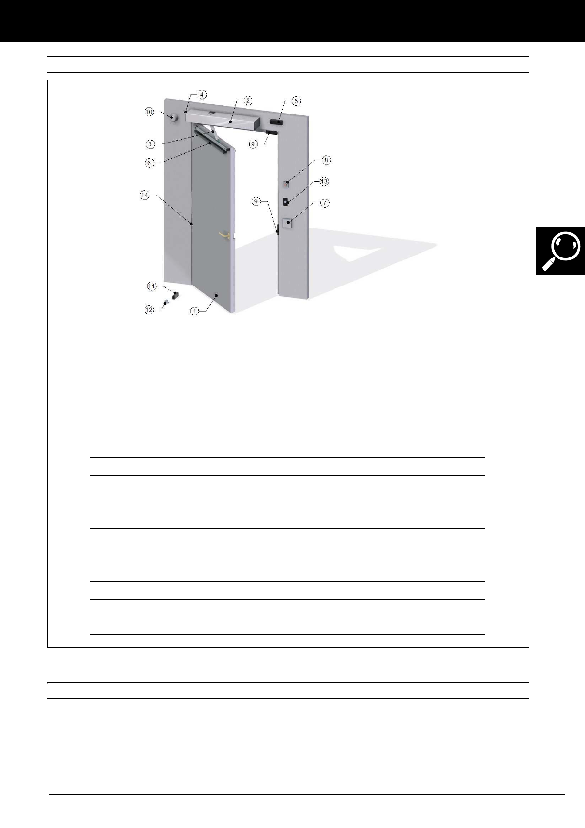
The necessary installation components are
indicated in the section "Elements of the
complete installation". The details and
instructions of all the components are
available on the web www.erreka.com.
Before installing the device, verify that the
door is in good mechanical condition, that it is
correctly balanced and that it opens and closes
correctly.
The operator is intended to be installed at a
height bellow 3 m above ground level or
another level of access.
Ensure that entrapment between the driven
part and the surrounding fixed parts is
prevented due to the opening movement of
the driven part except in the LOW ENERGY
mode.
In FULL ENERGY operation, safety sensors
must be installed in order to comply with
Standard EN 16005.
In LOW ENERGY operation, it is not
mandatory to use safety sensors as long as it is
not used by children and the elderly. It is
advisable to protect the area of the hinges to
avoid entrapment.
The details for the installation of the device are
indicated in the "Installation" chapter of this
manual. If you install protective devices not
supplied with this device, refer to the
instructions for those components.
Details on how to regulate the controls are
indicated in the section "Installation - Door
Configuration" of this manual.
After installation, make sure that the
mechanism is properly regulated and that the
protection system and any manual release
devices work correctly.
The list of all the components included in the
device is indicated in the section "Unpacking
and contents" of this manual.
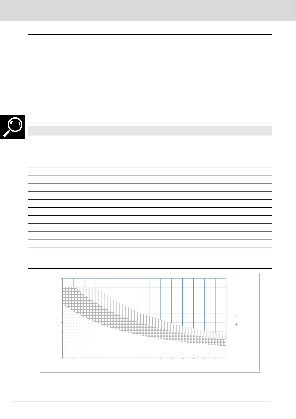
The specification of the type of door, gate or
window for which the appliance is intended,
size and mass of the activated part and
required torque are indicated in the "Operator
characteristics" section.
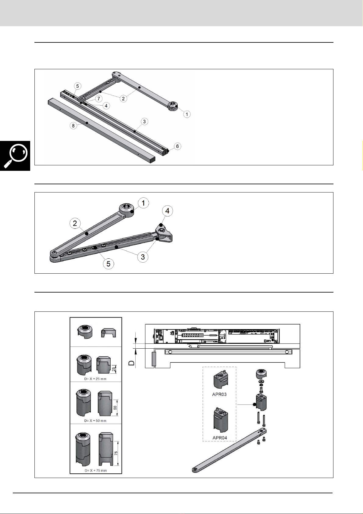
The position or positions the device can be
installed in can be seen in the "Operator
Installation" section of this guide.
WARNINGS FOR THE DISPOSAL
When this product reaches the end of its
useful life, it must be dismantled by qualified
personnel.
This product is made up of diverse materials,
some can be recycled and others must be
disposed of. It is necessary to find out about
the recycling and disposal systems provided by
the local regulations in force.
Some parts of this product may contain
polluting or hazardous substances that, if
released to the environment, could damage it
and human health.
It is forbidden to dispose of this
device together with household
waste. Carry out selective collection
according to local regulations.

GENERAL SAFETY INSTRUCTIONS
6Installation guide
1
SYMBOLS USED IN THIS GUIDE
This guide uses symbols to highlight specific texts. The
functions of each symbol are explained below:
Failure to respect the safety warnings could
lead to accident or injury.
Important details which must be respected for
correct assembly and operation.
Additional information to help the installer.
}Information on care for the environment.
2
IMPORTANCE OF THIS GUIDE
Read this guide in its entirety before carrying
out the installation, and obey all instructions.
Failure to do so may result in a defective
installation, leading to accidents and failures.
Moreover, this guide provides valuable information
which will help you to carry out installation more ef-
ficiently.
This guide is an integral part of the product. Keep
for future reference.
3
ENVISAGED USE
This operator has been designed exclusively to
automate swing doors in dry environments.
This operator is not suitable for installation in
inflammable or explosive environments.
Failure to install or use as indicated in this
guide is inappropriate and hazardous and
could lead to accidents or failures.
The installer shall be responsible for ensuring
the installation is set up for its envisaged use.
4
INSTALLER'S QUALIFICATIONS
Installation should be completed by a professional installer, complying with the following
requirements:
• He/she must be capable of carrying out
simple electrical installations in line with the
low voltage regulations and applicable
standards.
• He/she must be able to perform simple
mechanical installations.
Installation should be carried out taking into
account Standards EN16005.
5
OPERATOR SAFETY ELEMENTS
This operator meets all current safety standards.
However, the complete system comprises, apart from
the operator referred to in these instructions, other
elements which should be acquired separately.
The safety of the complete installation depends on
all the elements installed. Install only Erreka
components in order to guarantee proper
operation.
Respect the instructions for all the elements
used in the installation.
Installing safety elements is recommended.
For further information, see “Fig. 1 Elements of the
complete installation” on page 7".
6
DANGERS IN THE CLOSING EDGES
There may be a risk of crushing, trapping,
collision and dragging in the different closing
edges of the automatic doors.
7
MANUAL REVIEW
Manual review: 0.3. • Hardware Review: 2.1.
• Software version: 1.1.3.

English
330-Descripcion sw113.fm - 29/4/21
Automatic swing door PREMIS 200 7
OPERATOR DESCRIPTION
1
ELEMENTS OF THE COMPLETE INSTALLATION
Fig. 1 Elements of the complete installation
2
OPERATOR CHARACTERISTICS
Erreka swing operators are built to automate swing
pedestrian doors. Their multiple functions make them
ideal for automating any type of door: normal,
evacuation, smoke control, etc.
Speed, position and pushing force are controlled at all
times, ensuring compliance with the requirements of
Standard EN 16005.
ELECTRICAL CABLES:
Element Nº wires x section Remarks
Main power supply 3 x 1,5mm2
Selector 4 x 0,5mm2Screened cable
Safety sensor 6 x 0,5mm2Screened cable
Radar 4 x 0,5mm2
CAN (Double swing doors) 2 x 0,5mm2Screened cable
Stop 2 x 0,5mm2
Emergency 2 x 0,5mm2
Electrical lock (intercom) 2 x 0,5mm2With test; two more wires
Electrical lock (magnetic) 2 x 0,5mm2With test; two more wires
Hold-open retention magnets 2 x 0,5mm2
1Door
2 Operator
3 Arm: Pull / Push
4 Side switch
5 Activation sensor
6 Safety sensor
7 Selector
8 Emergency Stop
9 Electrical lock
10 Smoke sensor (Fire door)
11 “Hold-open” retention magnets
(Fire resistant door)
12 Door stopper
13 External key
14 Fingers guards

OPERATOR DESCRIPTION
330-Descripcion sw113.fm - 29/4/21
8Installation guide
General characteristics
•Work mode:
– Full Energy (Normal or Fire Door)
– Low Energy
•Control of open/close by way of encoder.
•Control of movement in closed loop (PID).
•Adjustable speeds and forces.
•Anti-crush.
•Cable connectors: Opening and closing safety
devices.
•Reset.
•Emergency input.
•Adjustable standby time.
•Master / Slave: Swing door synchronisation.
•Arms: Rigid and Articulated.
•Multifunction selector: Digital / Rotary.
•Side switch: manual / automatic / configurable.
•Multi-functions: Accessible toilets, etc.
•Peripherals power supply.
•Door closing spring.
Technical characteristics of the operator
Operation diagram
If it is necessary, parameters must be adjusted in each installation.
CHARACTERISTIC PREMIS200 PREMIS200M
Dimensions Operator 644x75x138 mm
Power supply (V/Hz) 230VAC - 50/60 Hz 125VAC 50/60Hz
Power consumed (VA) 85VA
Motor voltage (Vdc) 40V
Opening speed Adjustable 3 - 10 seconds
Closing speed Adjustable 5 - 10 seconds
Max. torque (Nm) 50
Opening angle Adjustable from 0 -100º (with mechanical stopper)
Maximum: Weight / Width door Operation diagram
Use Intensive
Network input fuse 4 A (5X20)
Peripherals power supply (voltage) 24 Volts
Peripherals power supply (current) 1.5 Amps
Service temperature (ºC) -20ºC - 50ºC
Protection rating (IP) IP52
450
400
350
300
250
200
150
100
50
0
650 700 750 800 850 900 950 1000 1050 1100 1150 1200 1250 1300 1350 1400
10 seg
6 seg
4 seg
Door width (mm)
Weight (kg)

OPERATOR DESCRIPTION
330-Descripcion sw113.fm - 29/4/21
Automatic swing door PREMIS 200 9
3
OPERATOR PARTS
Operator
Pull slide arm (APR01)
1Cover
2 Bracket profile
3 Control plate
4 Power plate
5 Spring force regulator
6 Side switch
7 Limit micro switch
8 Reduction unit
9 Motor
10 Side plastic cover
11 Side reset button
1 Shaft coupling
2 Rigid arm
3 Guide profile
4 Guide block
5 Limit switch
6 Side trim
7 Guide block shaft
8Spacer

OPERATOR DESCRIPTION
330-Descripcion sw113.fm - 29/4/21
10 Installation guide
Special Pull slide arm (APR09)
With the rigid arm and the door set back more than 100 mm, the door can be automated using these special arms
up to a maximum recess of 250 mm.
Articulated push arm (APR02)
Extension pivot (APR03 / APR04)
Extensions must be used when the operator needs to be installed at different heights relative to the door:
1 Acoplamiento eje
2 Brazos especiales
3 Perfil guía
4 Taco guía
5 Tope final de carrera
6 Embellecedor lateral
7 Eje Taco guía
8 Calzo distanciador
1 Shaft coupling
2 Special arms
3 Track profile
4 Track plug
5 Limit switch
6 Side trim
7 Track plug shaft
8Spacer
1 Shaft coupling
2Rigidarm
3 Telescopic arm
4 Coupling to door
5 Telescopic arm regulation screws
SIZE "X” COUPLING
25mm STANDARD
50mm STANDARD + APR03
75mm STANDARD + APR04
100mm STANDARD + APR03 + APR04
STANDARD
STANDARD
STANDARD + APR03
STANDARD + APR04
STANDARD+APR03+APR04
D=X (See assembly drawing)

330-Instalacion sw113.fm - 29/4/21
English
Automatic swing door PREMIS 200 11
INSTALLATION
1
TOOLS AND MATERIALS
Tool
•Drill
•Drill bits: ø 4.2 mm - ø 5 mm - ø 6 mm
•Set of Allen keys: 2,5 - 4 - 5
•Set of screwdrivers: Phillips - flathead
•Open-end wrench: 13
•Scissors
•Wire strippers
•Pencil
•Tape measure
•Spirit level
2
INITIAL CONDITIONS AND CHECKS
Initial conditions of the door
Check that the size of the door is within the
admissible range of the operator (see the
operator's technical characteristics).
Do not install the operator in a door which
does not work correctly in manual operation,
as this may lead to accidents. Repair the door
before installing.
The door must be provided with an opening
stopper.
The door must be easy to handle manually, namely:
• It must be balanced.
• There should be no stiffness throughout its
open/close.
Ambient conditions
This device is not suitable for installation in
inflammable or explosive environments.
Check that the admissible ambient
temperature range for the operator is suitable.
Electrical power supply installation
Ensure the power supply installation meets the following requirements:
• Rated voltage equal to that specified.
• Installation power greater than required
power.
• The electrical installation must comply with
low voltage regulations.
• The installation must be earthed.
3
UNPACKING
1Open the package and remove the contents from
within.
2Check the contents of the package (see figure
below).
If it is noticed that a piece is missing or deteriorated,
contact the nearest technical service.
}Discard the packaging in an environmentally friendly
manner, using recycling containers.
4
CONTENTS
1Swing operator
2Packing box
3Protectors
4Installation guide / user guide
5Screw set
6Erreka Sticker

330-Instalacion sw113.fm - 29/4/21
INSTALLATION
12 Installation guide
5
OPERATOR INSTALLATION
Check the installation space
Disassemble the operator's bracket profile
Minimu m dis ta nc e 10 mm
10 mm of space from the top of the operator.
The operator's fastening structure must be solid and
must not have significant deformation.
If the wall where the operator is to be secured is not strong and
reliable, a drilled metal plate can be provided on request to
36 37 38
14 15
1Remove the screws from the cover and extract it.
2Release the electronic plate's side switch cable and side
reset button cable.
3Release the geared motor screws (4) and remove the
entire body.
Fasten the bracket to the wall with the side covers,
since level X is referenced on the outside face of
the cover (installation drawings).
Side
switch
Reset
button

330-Instalacion sw113.fm - 29/4/21
Automatic swing door PREMIS 200 13
INSTALLATION
Pull slide arm (APR01) - operator on the lintel - hinges side
CHARACTERISTICS
Distance between shafts (hinge / arm)
EN Class
Opening angle
SWING
205 mm
4 - 6
100º
X=25mm
(Standard)
X=50mm
(Standard+APR03)
X=75mm
(Standard+APR04)
X=100mm
(Standard+APR03+APR04)
Y = 0 ÷ 100mm
(APR01)
Y = 100 ÷ 250mm
(APR09)
Max. angle 95º
HEIGHT SPACE
DOOR - OPERATOR
INSTALLATION MEASUREMENTS DOOR RETRACTION
DOOR - OPERATOR
OPENING DIRECTION
OPENING
DIRECTION
OPENING
DIRECTION

330-Instalacion sw113.fm - 29/4/21
INSTALLATION
14 Installation guide
Pull slide arm (APR01) - operator on the lintel - side opposite the hinges
CHARACTERISTICS
Distance between shafts (hinge / arm)
EN Class
Opening angle
SWING
205 mm
4 - 6
100º
X=2mm
(Standard)
X=27mm
(Standard+APR03)
X=52mm
(Standard+APR04)
X=77mm
(Standard+APR03+APR04)
Y = 0 ÷ 90mm
(APR01)
HEIGHT SPACE
DOOR - OPERATOR
INSTALLATION MEASUREMENTS DOOR RETRACTION
DOOR - OPERATOR
OPENING DIRECTION
OPENING
DIRECTION
OPENING
DIRECTION

330-Instalacion sw113.fm - 29/4/21
Automatic swing door PREMIS 200 15
INSTALLATION
Pull slide arm (APR01) - operator on the door - hinges side
CHARACTERISTICS
Distance between shafts (hinge / arm)
EN Class
Opening angle
SWING
205 mm
4 - 6
90º
X=5mm
(Standard)
X=30mm
(Standard+APR03)
X=55mm
(Standard+APR04)
X=80mm
(Standard+APR03+APR04)
Y = 0 ÷ 35mm
(APR01)
HEIGHT SPACE
DOOR - OPERATOR
INSTALLATION MEASUREMENTS DOOR RETRACTION
DOOR - OPERATOR
OPENING DIRECTION
OPENING
DIRECTION
OPENING
DIRECTION

330-Instalacion sw113.fm - 29/4/21
INSTALLATION
16 Installation guide
Pull slide arm (APR01) - operator on the door - side opposite the hinges
CHARACTERISTICS
Distance between shafts (hinge / arm)
EN Class
Opening angle
SWING
205 mm
3 - 6
100º
X=25mm
(Standard)
X=50mm
(Standard+APR03)
X=75mm
(Standard+APR04)
X=100mm
(Standard+APR03+APR04)
Y = 0 ÷ 35mm
(APR01)
HEIGHT SPACE
DOOR - OPERATOR
INSTALLATION MEASUREMENTS DOOR RETRACTION
DOOR - OPERATOR
OPENING DIRECTION
OPENING
DIRECTION
OPENING
DIRECTION

330-Instalacion sw113.fm - 29/4/21
Automatic swing door PREMIS 200 17
INSTALLATION
Push articulated arm (APR02) - operator on the lintel - side opposite the hinges
CHARACTERISTICS
Distance between shafts (hinge / arm)
EN Class
Opening angle
SWING
205 mm
4 - 6
100º
X=2mm
(Standard)
X=27mm
(Standard+APR03)
X=52mm
(Standard+APR04)
X=77mm
(Standard+APR03+APR04)
Y = 0 ÷ 210mm
(APR02)
HEIGHT SPACE
DOOR - OPERATOR
INSTALLATION MEASUREMENTS DOOR RETRACTION
DOOR - OPERATOR
OPENING DIRECTION
OPENING
DIRECTION
OPENING
DIRECTION

330-Instalacion sw113.fm - 29/4/21
INSTALLATION
18 Installation guide
Push articulated arm (APR02) - operator on the door - hinges side
CHARACTERISTICS
Distance between shafts (hinge / arm)
EN Class
Opening angle
SWING
205 mm
4 - 6
100º
X=5mm
(Standard)
X=30mm
(Standard+APR03)
X=55mm
(Standard+APR04)
X=80mm
(Standard+APR03+APR04)
Y = 0 ÷ 165mm
(APR02)
HEIGHT SPACE
DOOR - OPERATOR
INSTALLATION MEASUREMENTS DOOR RETRACTION
DOOR - OPERATOR
OPENING
DIRECTION
OPENING DIRECTION
OPENING
DIRECTION

330-Instalacion sw113.fm - 29/4/21
Automatic swing door PREMIS 200 19
INSTALLATION
Push articulated arm (APR09) - operator on the lintel - hinges side
CHARACTERISTICS
Distance between shafts (hinge / arm)
EN Class
Opening angle
SWING
205 mm
4 - 6
95
X=25mm
(Standard)
X=50mm
(Standard+APR03)
X=75mm
(Standard+APR04)
X=100mm
(
Standard
+APR03+APR04)
Y = 100 ÷ 250mm
Max. angle 95º
HEIGHT SPACE
DOOR - OPERATOR
INSTALLATION MEASUREMENTS DOOR RETRACTION
DOOR - OPERATOR
OPENING
DIRECTION
OPENING
DIRECTION

330-Instalacion sw113.fm - 29/4/21
INSTALLATION
20 Installation guide
Intermediate cover (APR05) for double swing doors
Intermediate cover subassembly
Assembling the intermediate cover
The side covers of the operators and the
intermediate casing must remain attached.
Make holes in the side covers to pass cables from
one operator to another.
X: Distance between operators
1Operator 1 cover
2Operator 2 cover
3Intermediate cover (APR05)
Parts:
1Intermediate cover
2Bracket profile
3Side covers
4Cover fastening point
5Cover fastening screw
Cutting:
•Disassemble the unit.
•Cut the bracket profile and
cover profile to X-5 mm.
•Reassemble the unit.
Other manuals for PREMIS 200
1
Table of contents
Other Erreka Door Opening System manuals
Popular Door Opening System manuals by other brands

samet
samet MonoLift manual

Siemens
Siemens 3VA9987-0GL30 quick start guide

DoorHan
DoorHan SHAFT-120 Installation and operating manual

Nabco
Nabco GYRO TECH GT-1175 Quick setup guide

D+H
D+H VRS 10 Original instructions

CornellCookson
CornellCookson FSNX-150EP Series Installation instructions and operation manual