Cabletron Systems CBUQBR User manual

CBUQBR
User Manual
Fivemere Ltd. Cabletron Systems Ltd.
Fivemere House Network House
161 High Street Newbury Business Park
Aldershot London Road, Newbury
Hampshire, England Berkshire, England
GU11 1TT RG13 2PZ
Telephone: [44] (0)1635 580000
Fax: [44] (0)1635 44578

CBUQBR User Manual
80-14004000-01ii
Publication — 80-14004000-01
Publication Notice:
This manual has been compiled and checked for accuracy. However the
information contained in this manual does not constitute a warranty of
performance. Cabletron Systems Ltd. reserves the right to revise this
publication from time to time without notice. Cabletron Systems Ltd.
assumes no liability for losses incurred as a result of out of date or incorrect
information contained in this manual.
Proprietary Notice:
© 1996-1997, Cabletron Systems Ltd., all rights reserved.
This document may not in whole or part be copied, photocopied, reproduced,
translated, or reduced to any electronic medium or machine-readable form
without prior consent from Cabletron Systems Ltd.
Approval Notice:
This equipment is approved for connection to all United Kingdom
telecommunications services, including British Telecom PLC, Hull City
Council and Mercury Communications, and is subject to the conditions set
out in these instructions for use.
All users of this equipment in UK and Europe must make themselves familiar
with the statutory instructions contained in Section 4.
Pan European Approval:
Where the Pan European Approval CE Mark ‘168X’ is applied to the product;
this approval is for connection of the ISDN interface within the European
Community (EC).
Approval in non EC countries is subject to local regulations in force, please
contact your Technical Support for information.
EMC Directive:
This product has been designed for use in Commercial and Light Industrial
environments and tested to relevant EMC Standards as listed in the
European O.J. All testing was carried out using screened interconnection
cables. Should the equipment be used in a different environment the user
may need to take additional EMC precautions.
Fivemere Ltd. is a subsidiary of Cabletron Systems Inc., USA.

CBUQBR User Manual
80-14004000-01 iii
History Sheet
80-14004000-01 V1.00 Software 20 March 1997

CBUQBR User Manual
80-14004000-01iv
TABLE OF CONTENTS
1THE QUAD BASIC RATE MODULE 1–1
1.1 INTRODUCTION 1–1
1.2 GENERAL DESCRIPTION 1–1
1.3 SHELF POWER LOADING 1–3
1.4 SWITCHES AND JUMPERS 1–4
1.4.1 8 WAY DIL SWITCH S2 - POLES 1-4 1–4
1.4.2 PRODUCT VARIANT - S2 POLES 5-8 1–5
1.4.3 4 WAY DIL SWITCH S3 1–5
1.4.4 JUMPERS AND LINKS 1–6
1.5 CBUQBR STATUS LEDS1–7
1.6 MANAGEMENT AND CONTROL 1–7
2OPERATION 2–1
2.1 INTRODUCTION 2–1
2.2 ISDN INTERFACES 2–1
2.3 CLOCKING 2–1
2.4 REAL TIME CLOCK 2–2
2.5 ALERTS 2–2
3COMMAND MENU 3–1
3.1 INTRODUCTION 3–1
3.2 CONFIGURATION 3–1
3.2.1 CONFIGURATION PRINCIPLES 3–1
3.2.2 SUGGESTED CONFIGURATION METHOD 3–2
3.3 COMMAND AND PARAMETER STRUCTURE 3–4
3.4 TOP LEVEL MENU 3–4
3.5 CONFIGURATION MENU 3–5
3.5.1 ALARMS MENU 3–5
3.5.2 ROUTING MENU 3–7
3.5.3 LINE CONFIGURATION MENU 3–9
3.5.4 ISDN MENU 3–10
3.5.5 CLOCK MODE 3–10
4EUROPEAN APPROVALS INFORMATION 4–1
5GLOSSARY OF TERMS 5–1

The Quad Basic Rate Module
80-14004000-01 1–1
1 The Quad Basic Rate Module
1.1 Introduction
The Cyber Backup Quad Basic Rate Module (CBUQBR) is a single width
card for use in either the CBU/14 or the CBU/6 Shelf, otherwise known
as a ‘Shelf System’.
The CBUQBR connects to 4 basic rate ISDN lines providing up to 8 ‘B’
channels for interfacing with other application cards in the Fivemere-
Cabletron Shelf System. A Shelf System supports a single CBUQBR or
a single CBUPRI but not both simultaneously. (Please see section 5 for
the Glossary of Terms used in this manual).
Management is provided via the Cyber Backup Generic Shelf Manager
(CBUGSM) which forms a standard part of the Shelf System.
Local or remote access to the cards in the shelf is by password which is
entered on the first poll of the shelf. Alarm messages from the cards in
the shelf are routed to the alarm and/or command ports on the
CBUGSM.
For cards other than the CBUQBR used in the Shelf System, please see
the relevant manual.
1.2 General Description
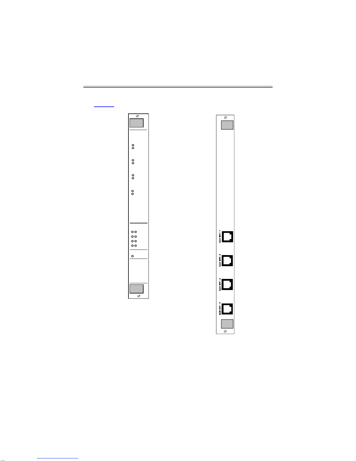
The CBUQBR comprises a front card and a rear interface card.
CBUQBR User Manual
80-14004000-011–2
The front and rear panel layouts for the CBUQBR are shown below in
Figure 1.
Ch. in Use
CBU
Alert
B1
B2
BRI 2
B1
B2
BRI 3
B1
B2
BRI 1
B1
B2
BRI 4
ISDN
L1 L2 BRI 1
BRI 2
BRI 3
BRI 4
QBR
Figure 1 - CBUQBR Front and rear panels

The Quad Basic Rate Module
80-14004000-01 1–3
The CBUQBR provides up to 8 x 64kbit/s ‘B’ channels, each channel can
be switched to any time-slot on any of the four 2.048 Mbit/s backplane
buses.
The CBUQBR will provide on demand individual 64 kbit/s channels for
use by other application cards in the shelf. The other application cards
are completely responsible for the provision of telephone numbers,
CLIDs, dial commands, timers, and call retry attempts.
Software download to the module is supported via the CBUGSM.
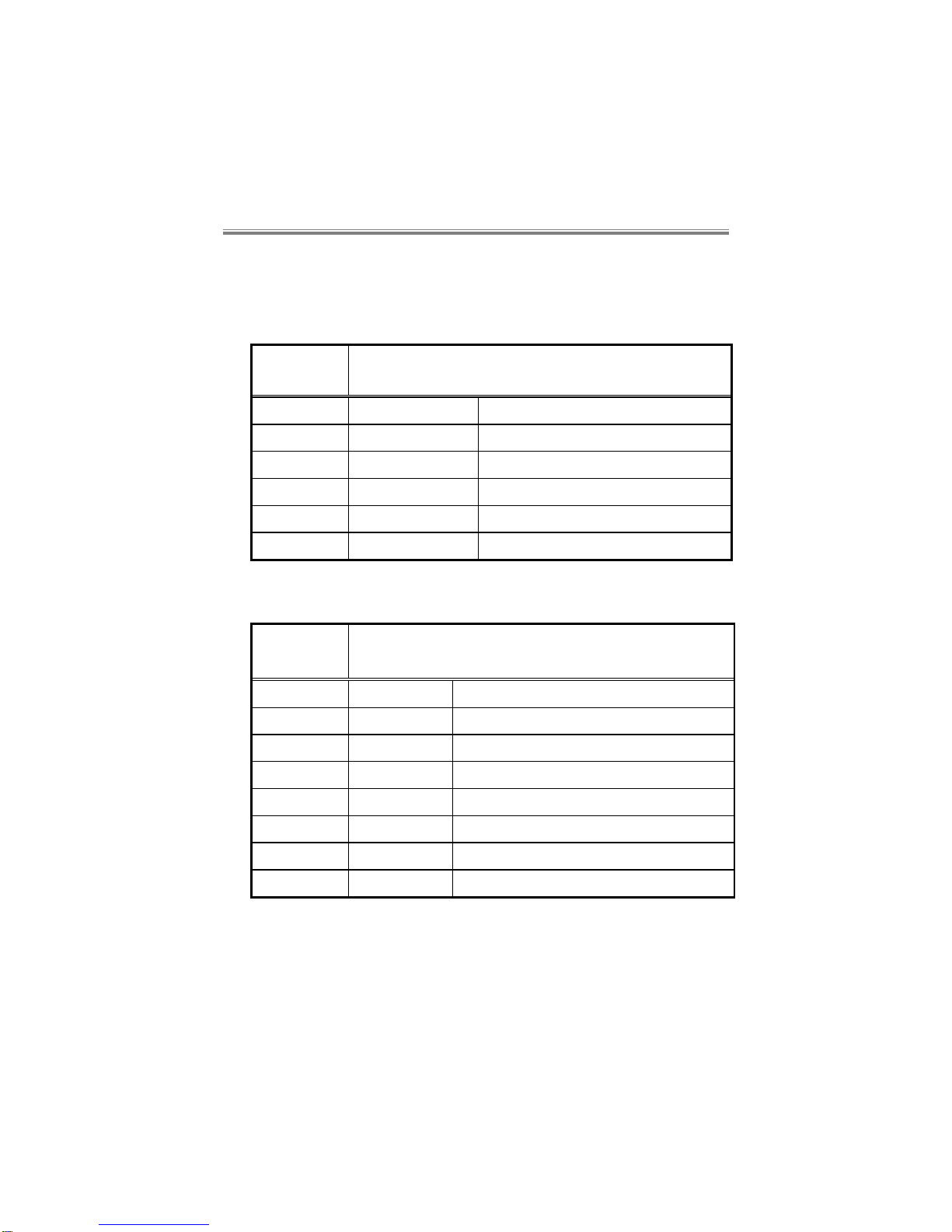
1.3 Shelf Power Loading
The CBUQBR requires the following current on the power rails:
+5V +12V -12V
300mA 5mA 5mA
When installing cards into either type of shelf, the installation engineer
must ensure that the shelf power supplies’ combined output can meet
both the overall power requirements and the individual rail current
requirements of all the cards in the shelf. (Please refer to the relevant
manuals for this information on the cards). This is true whether allowing
for redundancy or not.
Warning:
The Shelf should be professionally installed by a competent
engineer. There are no operator serviceable parts inside the
unit and it should only be opened by a qualified service
engineer. The mains supply should be disconnected before
accessing the interior.
Gefäh! Bereich. Nur für fachpersonal. Nicht öffnen
berührungsgefahr!
Zone dangereuse! reservée au personnel autorisé. Ne pas
ouvrir. Tensions dangereuses.

CBUQBR User Manual
80-14004000-011–4
1.4 Switches and Jumpers
All switches and jumpers must only be changed by a competent
engineer.
1.4.1 8 Way DIL Switch S2 - poles 1-4
Pole 1 OFF (F) Reserved
Pole 2 OFF (F) ‘S’ bus power detection enabled
ON ‘S’ bus power detection disabled
Pole 3 OFF (F) Normal Operation
ON Factory Default.
(It must subsequently be turned OFF
again after powering up to perform a
factory default, to return the CBUQBR
back to normal operation)
Pole 4 OFF System Slave Function
ON (F) System Master Function.
This enables the call control and routing
functions, resident on the CBUQBR.
Poles 5-8 Variant selection, see section 1.4.2.

The Quad Basic Rate Module
80-14004000-01 1–5
1.4.2 Product Variant - S2 Poles 5-8
Different operational modes or product “variants” can be selected via the
8 way DIL switch on the pcb, allowing several different countries and
variants to use the same software.
DIL switch S1 poles 5, 6, 7 and 8 define the variant in binary notation.
Pole 5 = L.S.B., pole 8 = M.S.B., (L.S.B.=Least Significant Bit,
M.S.B.=Most Significant Bit).
Variant Country DIL Switch Settings
Variant 0(F) Euro ISDN. UK and most
European countries: poles 5,6,7,8 all
OFF.
Variant 2 Euro ISDN*. France and
Sweden: pole 6 ON,
poles 5,7,8 OFF.
Variant 3 USA AT&T: poles 5,6 ON,
poles 7,8 OFF.
‘F’ is the factory setting, and must not be changed otherwise malfunction
may occur. All poles are ‘read’ by the software on power up.
*NOTE: Variant 2 does not have single octet information elements
present in the call setup message.
Most other countries with Euro-ISDN are likely to require Variant 0.
Please contact your Technical Support for further information.
NOTE: Variants 1-14 must not be set in the UK, otherwise the
Approval of this product will be invalidated. Access to the
interior to change these settings must only be made by a
competent engineer.
1.4.3 4 Way DIL Switch S3
Poles 1-4 ON (F) Not used
CBUQBR User Manual
80-14004000-011–6
1.4.4 Jumpers and Links
Front card:
These are all factory set and must not be changed.
Jumper Description
(F=Factory Set)
JP1-3 - Not used
JP4 - Clock post
JP5 OUT (F) Watchdog timer enabled
JP6 OUT (F) Rear card absence enables re-boot
JP7-11 MASTER (F) System Bus Master operation
SLAVE System Bus Slave operation
Rear card:
Jumper Description
(F=Factory Set)
JP1 OUT (F) Tx ISDN line 1 termination disabled
JP2 OUT (F) Rx ISDN line 1 termination disabled
JP3 OUT (F) Tx ISDN line 2 termination disabled
JP4 OUT (F) Rx ISDN line 2 termination disabled
JP5 OUT (F) Tx ISDN line 3 termination disabled
JP6 OUT (F) Rx ISDN line 3 termination disabled
JP7 OUT (F) Tx ISDN line 4 termination disabled
JP8 OUT (F) Rx ISDN line 4 termination disabled
Table of contents
Other Cabletron Systems Computer Hardware manuals

Popular Computer Hardware manuals by other brands

EMC2
EMC2 VNX Series Hardware Information Guide

Panasonic
Panasonic DV0PM20105 Operation manual

Mitsubishi Electric
Mitsubishi Electric Q81BD-J61BT11 user manual

Gigabyte
Gigabyte B660M DS3H AX DDR4 user manual

Raidon
Raidon iT2300 Quick installation guide

National Instruments
National Instruments PXI-8186 user manual


