ST X-NUCLEO-SAFEA1B Operating instructions

Introduction
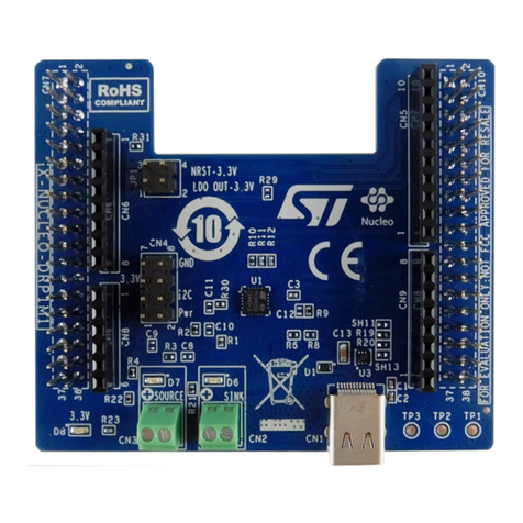
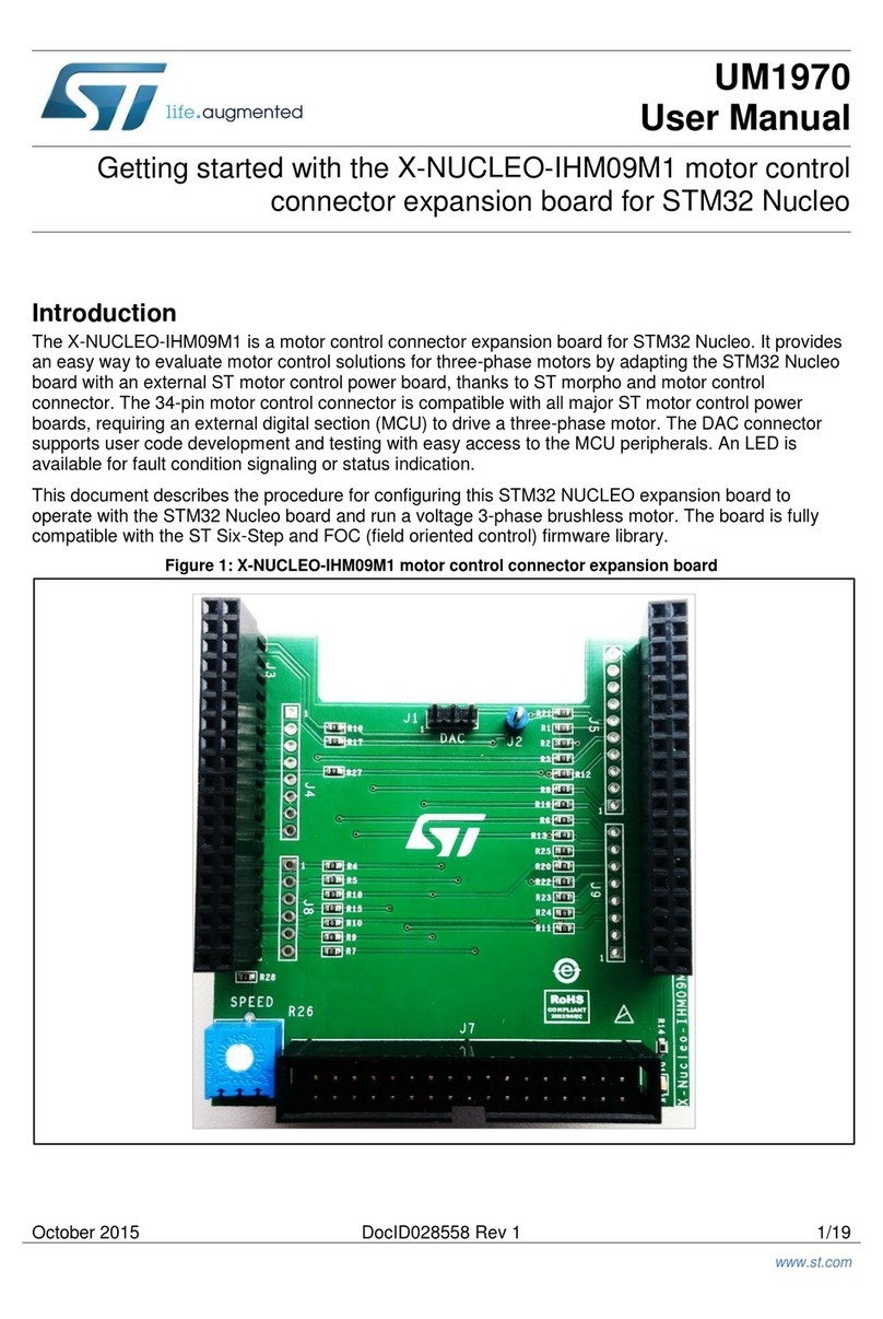
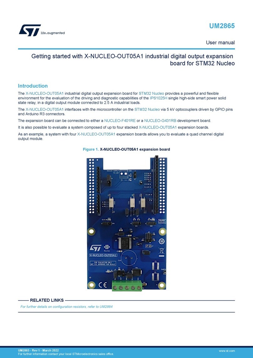
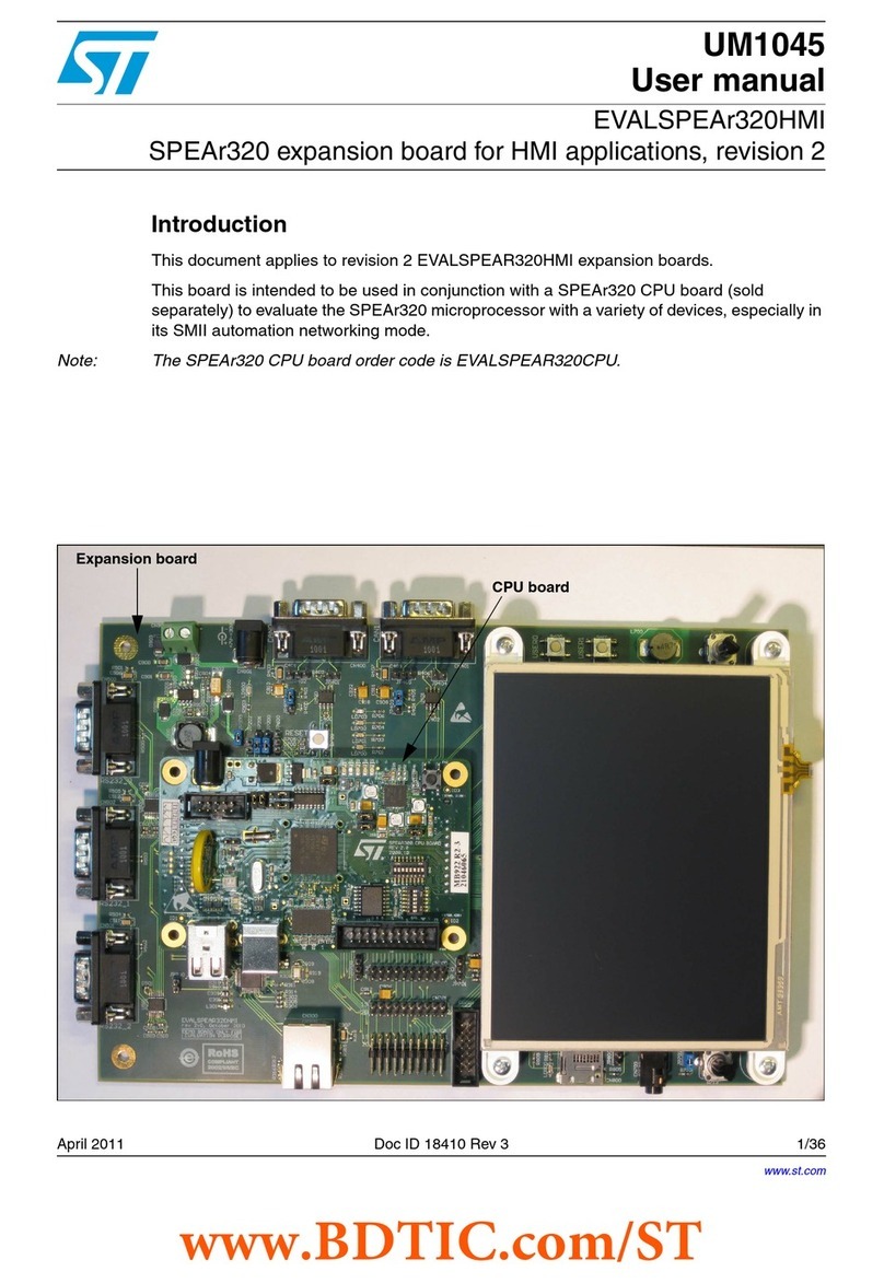
The X-NUCLEO-SAFEA1B expansion board is based on the STSAFE-A110 secure element. It can be used with any STM32
Nucleo development board.
The on-board STSAFE-A110 is customized with a standard profile for evaluation and is compatible with the Arduino UNO R3
connector.
The X-NUCLEO-SAFEA1B expansion board is used with free X-CUBE-SAFEA1 or X-CUBE-SBSFU software packages
containing sample code to demonstrate how to implement security applications.
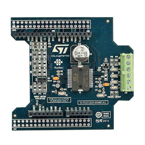
Figure 1. X-NUCLEO-SAFEA1B
How to use STM32 Nucleo expansion board based on the STSAFE-A110 secure
element
UM3195
User manual
UM3195 - Rev 1 - June 2023
For further information contact your local STMicroelectronics sales office. www.st.com

1 Getting started
1.1 Hardware requirements
The X-NUCLEO-SAFEA1B expansion board can be connected to any STM32 Nucleo development board through
the matching Arduino UNO R3 connector pins.
Note: Handle the X-NUCLEO-SAFEA1B with care and avoid bending or damaging the pins as the board has male/
female pass-through connectors and ESD sensitive components.
1.2 System requirements
To complete the system setup, you need:
• a PC running Windows version 7, 8 or 10
• a USB type A to mini-B USB cable to connect the STM32 Nucleo to the PC
• software package (X-CUBE-SAFEA1 or X-CUBE-SBSFU) installed on the user PC
• one of the compatible software development environments: IAR, Arm Keil, AC6, or Atolic
UM3195
Getting started
UM3195 - Rev 1 page 2/16

2 Hardware description
The X-NUCLEO-SAFEA1B expansion board has an embedded STSAFE-A110 secure element to allow you to
evaluate its authentication and data management services connected to a local or remote host.
This STSAFE-A110 is factory personalized with a generic sample profile.
The main features of the X-NUCLEO-SAFEA1B expansion board are:
• On-board STSAFE-A110 customized with a standard evaluation profile
• HE10 extension connector to mount additional STSAFE devices
• Arduino UNO R3 connector
• Free drivers, middleware and software samples compatible with the STM32 ODE
• RoHS and WEEE compliant
The X-NUCLEO-SAFEA1B interfaces with the STM32 Nucleo microcontrollers via the I²C communication bus.
2.1 Jumpers and solder bridges
Table 1. X-NUCLEO-SAFEA1B expansion board jumper and solder bridge functions
Jumper Alternative soldering point function
P1 SB13 Connects embedded LD3 green LED to STM32 Nucleo board
P4 SB1 Connects embedded 2.2kΩ pull-ups to I²C bus for SCL
P5 SB2 Connects embedded 2.2kΩ pull-ups to I²C bus for SDA
P7 Can be used to put STSAFE-A110 secure element in reset mode
SB5 Can be used to drive the STSAFE-A110 reset pin via the STM32 MCU PC0 GPIO
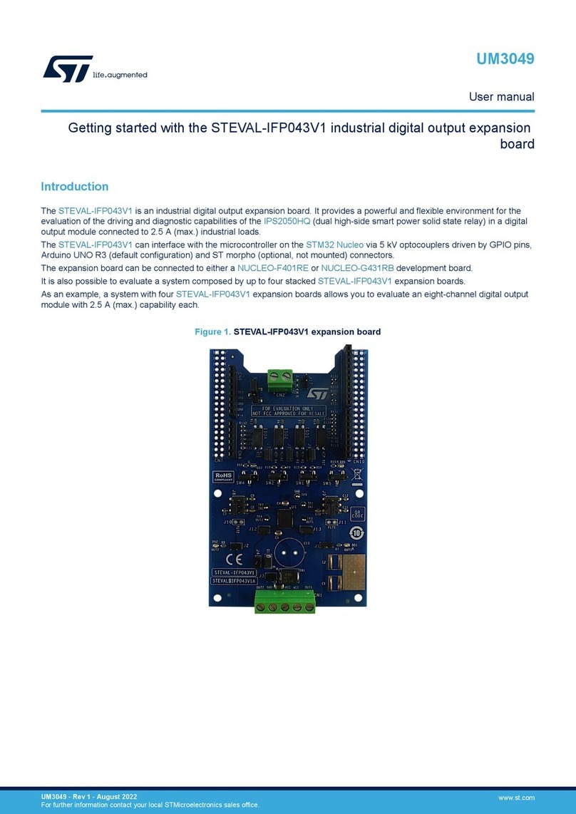
2.2 Connector
X-NUCLEO-SAFEA1B Nucleo expansion board has an HE10 extension connector (J2) to mount an additional
STSAFE-A1xx secure element.
Note: If you use the connector to accommodate new generation STSAFE-A devices, be sure that you insert jumper P7
to place the current STSAFE-A110 secure element soldered on the board in reset mode.
UM3195
Hardware description
UM3195 - Rev 1 page 3/16

3 STM32L4 series microcontroller software
The STM32 ODE software package X-CUBE-SAFEA1 provides demonstration source code for a NUCLEO-
L476RG development board with X-NUCLEO-SAFEA1B expansion. The X-CUBE-SAFEA1 package includes
drivers, middleware and several demonstration codes that implement the features of the STSAFE-A110 device
through a host microcontroller. The demonstration codes use the STSAFE-A1xx middleware built on the
STM32Cube software technology. They illustrate authentication, key pair generation, key establishment, local
envelope wrapping and pairing features.
Another package, called X-CUBE-SBSFU, provides demonstration source code for Secure Boot and Secure
Firmware Update solution. It updates of the STM32 microcontroller firmware with new features and addresses
potential issues. The update process is a secure operation using the STSAFE-A110 to prevent unauthorized
updates and access to confidential on-device data. It is available for the STM32L4 Series microcontrollers with
examples provided for the B-L475E-IOT01A discovery kit with the X-NUCLEO-SAFEA1B expansion.
UM3195
STM32L4 series microcontroller software
UM3195 - Rev 1 page 4/16

4 Schematic diagrams
Figure 2. X-NUCLEO-SAFEA1 circuit schematic - STSAFE-A chips
4GND
SCL 7
IC4
GND
4
3NC
3V3
NC 6
3V3
1RST
NC
3
C3
VCC
2
RESET-C2
3V3
100nF/25V
100nF/25V
NC
1
STSAFE-A110 UFDFPN8 3x2
C2
IC1
SDA 5
GND
SDA 5
SCL
IC2
GND
4
STSAFE-A110 SO8N
2VCC
3NC
2VCC
SDA
RESET-C1
SDA
STSAFE-A110 UFDFPN8 3x2
SCL
RESET-C1
GND
RST
1
NC 6
RST 8
SCL
7
SCL 2VCC
7
SCL
NC 8
SCL
RESET-C2
SDA
RST 8
IC3
1NC
NC
3
NC 6
GND
SDA
STSAFE-A110 SO8N
SCL 7
NC 8
3V3
4GND
GND
NC 6
SDA 5
SDA 5
UM3195 - Rev 1 page 5/16
UM3195
Schematic diagrams

Figure 3. X-NUCLEO-SAFEA1 circuit schematic - Arduino and morpho connectors
morpho connector
8
32
18
13
CN10
CN9
10
28
9
4
PA9
7
2
3
16
GND
33
34
21 22
14
CN6
3V3
2
3
4
5
5
Arduino connector
2
17
12
Header 19x2
9
3 5
GND
1
21 22
25
SPI_CLK
27
34
11
1
1
8
29 30
4
23 24
1
4
13
12
35 36
11
20
31
PC0
PC1
2
1
CN5
SPI_MOSI
SPI_MISO
SPI_NSS 16 6
7
8
Header 19x2
26
6
CN8
8
7
6
10
15
19
7
9
5
28
29
38
37
CN7
25
PA10
7
2
19
E5V
30
10
5
1
3
3
14
15
5V
PA11
PA12
PH1
PH0
morpho connector
2
27
SDA
SCL
31
5
8
26
4
3
6
20
6
4
CN5-6
32
33
6
35 36
1817
23 24
38
37
Arduino connector
Arduino connector Arduino connector
UM3195 - Rev 1 page 6/16
UM3195
Schematic diagrams

Figure 4. X-NUCLEO-SAFEA1 circuit schematic - LEDs and jumpers
1K
R8
2K2
1%
2
P4
2
R5
1KR
PC0
(CN8-Pin 6)
LD3
SDA
3V3
1%
RST1
SDA
SCL pull-up
SCL
61.9R
1
Amber LED
P7
RESET-C1
1%
1
1%
2
P5
SDA pull-up
GND
8
GND
3V3
1
9
4
R3
CN5-6
3V33V3
R7
R1
SPI_MOSI
2
P1
SB5
Sel SCL Sel SDA
pull-up
RST1 CMD
pull-up
SPI_MISO
SPI_CLK
SPI_NSS
2
820R
1
3
3V3
1%
User Led
Header 5X2 male
6
GND
10
J2
SCL
7
(CN5-Pin 9)
SB13
1%
LD1
2K2
5
1
R4
(CN5-Pin 10)
Green LED
SB2
SB1
UM3195 - Rev 1 page 7/16
UM3195
Schematic diagrams

5 Bill of materials
Table 2. X-NUCLEO-SAFEA1B bill of materials
Item Q.ty Reference Part/Value Description Manufacturer Order code
1 1 C2
0.1 µF 0603 [1608
Metric] 25 V ± 10 %
SMD X7R
Multilayer ceramic
capacitor Multicomp MC0603B104K250CT
2 0 C3 0.1 µF 0603 [1608
Metric] 25 V ± 10 %
Multilayer ceramic
capacitor (not
mounted)
Multicomp MC0603B104K250CT
3 0 C4, C5
22 pF 0603 [1608
Metric] 50 V ± 5%
C0G/NP0
Multilayer ceramic
capacitors (not
mounted)
Multicomp MC0603N220J500CT
4 1 CN5
Vertical, 2.54 mm, 10
contacts, receptacle,
ESQ series, through
hole
Board-to-board
connector SAMTEC ESQ-110-24-T-S
5 1 CN6
Vertical, 2.54 mm, 8
contacts, receptacle,
ESQ series, through
hole
Board-to-board
connector SAMTEC ESQ-108-24-T-S
6 0 CN7
Vertical, 2.54 mm, 38
contacts, receptacle,
ESQ series, through
hole
Board-to-board
connector (not
mounted)
SAMTEC ESQ-119-14-G-D
7 1 CN8
Vertical, 2.54 mm, 6
contacts, receptacle,
ESQ series, through
hole
Board-to-board
connector SAMTEC ESQ-106-24-T-S
8 1 CN9
Vertical, 2.54 mm, 8
contacts, receptacle,
ESQ series, through
hole
Board-to-board
connector SAMTEC ESQ-108-24-T-S
9 0 CN10
Vertical, 2.54 mm, 38
contacts, receptacle,
ESQ series, through
hole
Board-to-board
connector (not
mounted)
SAMTEC ESQ-119-14-G-D
10 1 IC1 STSAFE-A110 SO8N
Authentication and
brand protection
secure solution
ST STSAFA110DFSPL03
11 0 IC2 STSAFE-A110 SO8N
Authentication and
brand protection
secure solution (not
mounted)
ST STSAFA110DFSPL03
12 0 IC3, IC4 STSAFE-A110 DFN23
Authentication and
brand protection
secure solution (not
mounted)
ST STSAFA110DFSPL03
13 1 LD1 SM0805AC, 6MCD,
607 Amber LED Bivar Inc. SM0805AC
14 0 LD2 SM0805AC, 6MCD,
607
Amber LED (not
mounted) Bivar Inc. SM0805AC
15 1 LD3 1.8 V 2 mA 570 nm Green LED OSRAM LGT67K-H2K1-24-Z
16 0 J1
Receptacle, 5 ways,
surface mount, right
angle
USB connector,
shielded, Micro
USB Type B, USB
2.0 (not mounted)
MOLEX 47346-0001
UM3195
Bill of materials
UM3195 - Rev 1 page 8/16

Item Q.ty Reference Part/Value Description Manufacturer Order code
17 1 J2
2.54 mm, 10 contacts,
header, 303 Series,
through hole, 2 rows
Wire-to-board
connector 3M 30310-6002HB
18 1 P7, P8 473, 80 way, 2 row,
straight pin header Connector Stelvio Kontek 613080262822
19 1 R1 61.9 ohm 0603 [1608
Metric] 75 V 100 mW Thick film resistor MULTICOMP MCWR06X61R9FTL
20 0 R2 680 ohm 0603 [1608
Metric] 50 V 100 mW
Thick film resistor
(not mounted) MULTICOMP MCWR06X6800FTL
21 4 R3, R4, R7,
R8
2.2 kohm 0603 [1608
Metric] 50 V 100 mW
SMD
Chip resistors MULTICOMP MCWR06X2201FTL
22 1 R5 1 kohms 0603 [1608
Metric] ±1% Resistor MULTICOMP MCMR06X1001FTL
23 0 R6 1 kohms 0603 [1608
Metric] ±1%
Resistor (not
mounted) MULTICOMP MCMR06X1001FTL
24 3 SB1, SB2,
SB13
0 ohm 0603 [1608
Metric] 75 V 100 mW Chip resistor Vishay CRCW06030000Z0EA
25 0 SB3, SB10,
SB11, SB12
0 ohm 0603 [1608
Metric] 75 V 100 mW
Chip resistor (not
mounted) Vishay CRCW06030000Z0EA
26 0 X1
8 MHz, through hole,
11.5 mm x 5 mm, 10
ppm, 18 pF, 10 ppm,
9B Series
9B-8.000MEEJ-B -
Crystal, TXC Corp. 9B-8.000MEEJ-B
UM3195
Bill of materials
UM3195 - Rev 1 page 9/16

6 Board versions
Table 3. X-NUCLEO-SAFEA1 versions
CPN Finished good Schematic diagrams Bill of materials
X-NUCLEO-SAFEA1B X$NUCLEO-SAFEA1B (1) X$NUCLEO-SAFEA1B
schematic diagrams
X$NUCLEO-SAFEA1B bill of
materials
1. This code identifies the X-NUCLEO-SAFEA1B evaluation board first version.
UM3195
Board versions
UM3195 - Rev 1 page 10/16

7 Regulatory compliance information
Notice for US Federal Communication Commission (FCC)
For evaluation only; not FCC approved for resale
FCC NOTICE - This kit is designed to allow:
(1) Product developers to evaluate electronic components, circuitry, or software associated with the kit to
determine
whether to incorporate such items in a finished product and
(2) Software developers to write software applications for use with the end product.
This kit is not a finished product and when assembled may not be resold or otherwise marketed unless all
required FCC equipment authorizations are first obtained. Operation is subject to the condition that this product
not cause harmful interference to licensed radio stations and that this product accept harmful interference. Unless
the assembled kit is designed to operate under part 15, part 18 or part 95 of this chapter, the operator of the kit
must operate under the authority of an FCC license holder or must secure an experimental authorization under
part 5 of this chapter 3.1.2.
Notice for Innovation, Science and Economic Development Canada (ISED)
For evaluation purposes only. This kit generates, uses, and can radiate radio frequency energy and has not been
tested for compliance with the limits of computing devices pursuant to Industry Canada (IC) rules.
À des fins d'évaluation uniquement. Ce kit génère, utilise et peut émettre de l'énergie radiofréquence et n'a pas
été testé pour sa conformité aux limites des appareils informatiques conformément aux règles d'Industrie Canada
(IC).
Notice for the European Union
This device is in conformity with the essential requirements of the Directive 2014/30/EU (EMC) and of the
Directive 2015/863/EU (RoHS).
Notice for the United Kingdom
This device is in compliance with the UK Electromagnetic Compatibility Regulations 2016 (UK S.I. 2016 No. 1091)
and with the Restriction of the Use of Certain Hazardous Substances in Electrical and Electronic Equipment
Regulations 2012 (UK S.I. 2012 No. 3032).
UM3195
Regulatory compliance information
UM3195 - Rev 1 page 11/16

Revision history
Table 4. Document revision history
Date Revision Changes
13-Jun-2023 1 Initial release.
UM3195
UM3195 - Rev 1 page 12/16

Contents
1Getting started ....................................................................2
1.1 Hardware requirements .........................................................2
1.2 System requirements ...........................................................2
2Hardware description ..............................................................3
2.1 Jumpers and solder bridges......................................................3
2.2 Connector.....................................................................3
3STM32L4 series microcontroller software ..........................................4
4Schematic diagrams ...............................................................5
5Bill of materials....................................................................8
6Board versions ...................................................................10
7Regulatory compliance information ...............................................11
Revision history .......................................................................12
UM3195
Contents
UM3195 - Rev 1 page 13/16

List of figures
Figure 1. X-NUCLEO-SAFEA1B...............................................................1
Figure 2. X-NUCLEO-SAFEA1 circuit schematic - STSAFE-A chips ......................................5
Figure 3. X-NUCLEO-SAFEA1 circuit schematic - Arduino and morpho connectors............................6
Figure 4. X-NUCLEO-SAFEA1 circuit schematic - LEDs and jumpers .....................................7
UM3195
List of figures
UM3195 - Rev 1 page 14/16

List of tables
Table 1. X-NUCLEO-SAFEA1B expansion board jumper and solder bridge functions ...........................3
Table 2. X-NUCLEO-SAFEA1B bill of materials .....................................................8
Table 3. X-NUCLEO-SAFEA1 versions ..........................................................10
Table 4. Document revision history .............................................................12
UM3195
List of tables
UM3195 - Rev 1 page 15/16

IMPORTANT NOTICE – READ CAREFULLY
STMicroelectronics NV and its subsidiaries (“ST”) reserve the right to make changes, corrections, enhancements, modifications, and improvements to ST
products and/or to this document at any time without notice. Purchasers should obtain the latest relevant information on ST products before placing orders. ST
products are sold pursuant to ST’s terms and conditions of sale in place at the time of order acknowledgment.
Purchasers are solely responsible for the choice, selection, and use of ST products and ST assumes no liability for application assistance or the design of
purchasers’ products.
No license, express or implied, to any intellectual property right is granted by ST herein.
Resale of ST products with provisions different from the information set forth herein shall void any warranty granted by ST for such product.
ST and the ST logo are trademarks of ST. For additional information about ST trademarks, refer to www.st.com/trademarks. All other product or service names
are the property of their respective owners.
Information in this document supersedes and replaces information previously supplied in any prior versions of this document.
© 2023 STMicroelectronics – All rights reserved
UM3195
UM3195 - Rev 1 page 16/16
Table of contents
Other ST Computer Hardware manuals

ST
ST X-NUCLEO-IHM13A1 User manual

ST
ST CLT01-38SQ7 User manual

ST
ST STM32H7 Series Owner's manual

ST
ST ST25DV-DISCOVERY User manual

ST
ST X-NUCLEO-OUT12A1 User manual

ST
ST STM32F3DISCOVERY User manual

ST
ST UM2967 User manual

ST
ST X-NUCLEO-LED12A1 User manual

ST
ST X-NUCLEO-NFC01A1 User manual

ST
ST X-NUCLEO-53L1A1 User manual