3
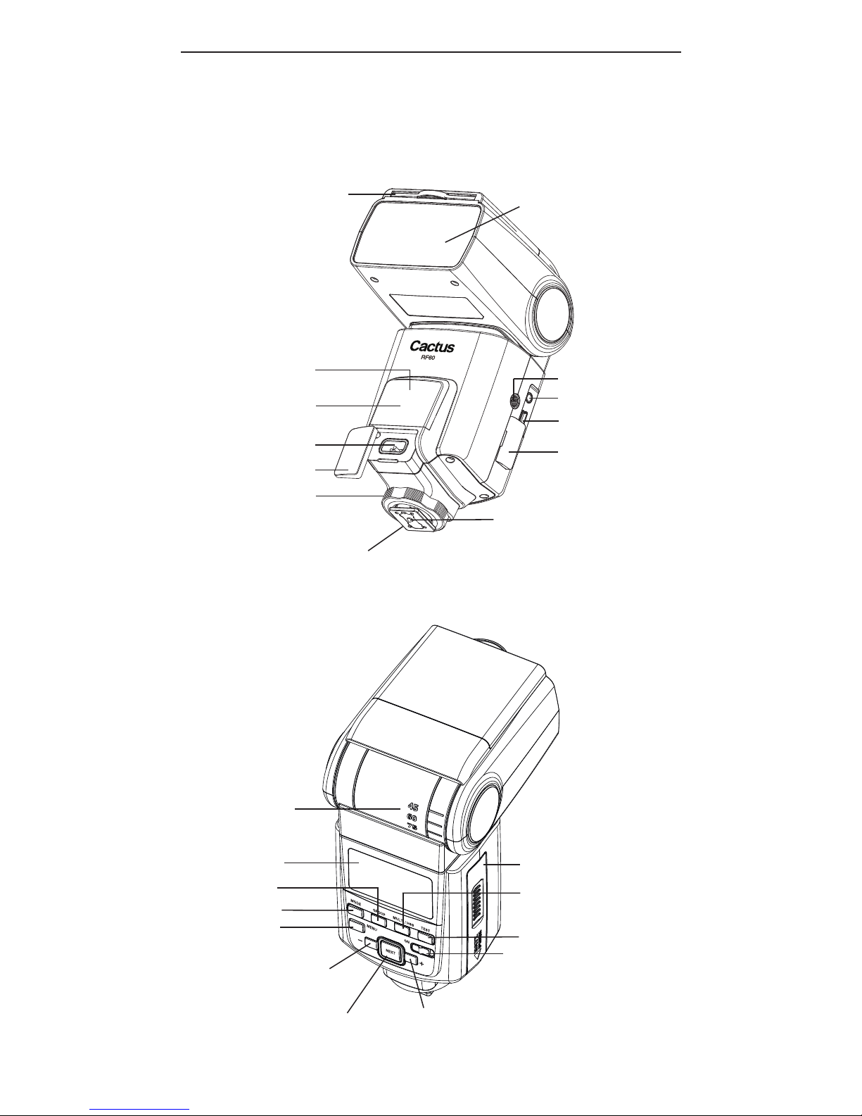
1. Getting to Know your
RF60X
Thank you for purchasing the Cactus
Wireless Flash RF60X. The RF60X is
u n iq u e a m o n g oth e r a s h e s
available in the market. With a built-
in transmitter and receiver, it not
only receives wireless signals, but
also functions as a commander to
control other RF60X or RF60. The
possibilities are endless!
This new RF60X features outstanding
improvement from its predecessor:
–Exclusive! Cooling mode to prevent
RF60X from overheat cut-off;
–Quick full-power recharge time at
1.9 s;
–Auto-focus assist light in sync
with other Cactus devices;
–Automatic wireless HSS support in
Slave mode for Canon, Fujifilm,
Nikon, Olympus, Panasonic, Pentax
when working with V6 II; and Sony
with V6 IIs transceiver.
Other features include:
–Built-in wireless commander and
receiver
–Remote control of power and zoom
levels
–Group control of up to four groups
with configurable Group Alias
–Optical slave with delay feature
–High power up to Guide Number of
56 meters