Caen ELS WPOLINV200XA User manual

Polarity Inverters
200 A, 400 A, 600 A
Polarity Inverters
User’s Manual
All Rights Reserved
© CAEN ELS s.r.l.
Rev. 1.2 –November 2022
POLARITY INVERTERS

2
This product is
&
compliant.
CAEN ELS s.r.l.
c/o AREA Science Park
S.S. 14 km 163,5 - 34149 Basovizza (TS)
Italy
Mail: [email protected]
Web: www.caenels.com

3
POLARITY INVERTERS - USER’S MANUAL
This manual covers the following standard models:
WPOLINV200XA
WPOLINV400XA
WPOLINV600XA
For technical assistance please refer to the following contact:
CAEN ELS S.R.L.
SS14 km 163,5
34149 Basovizza (TS) –Italy
(c/o Area Science Park –Building Q1)
Phone: +39 040 375 6610
Fax: +39 040 375 6611
Mail: [email protected]

Polarity Inverters –User’s Manual
4
Table of contents
1. INTRODUCTION................................................................................................9
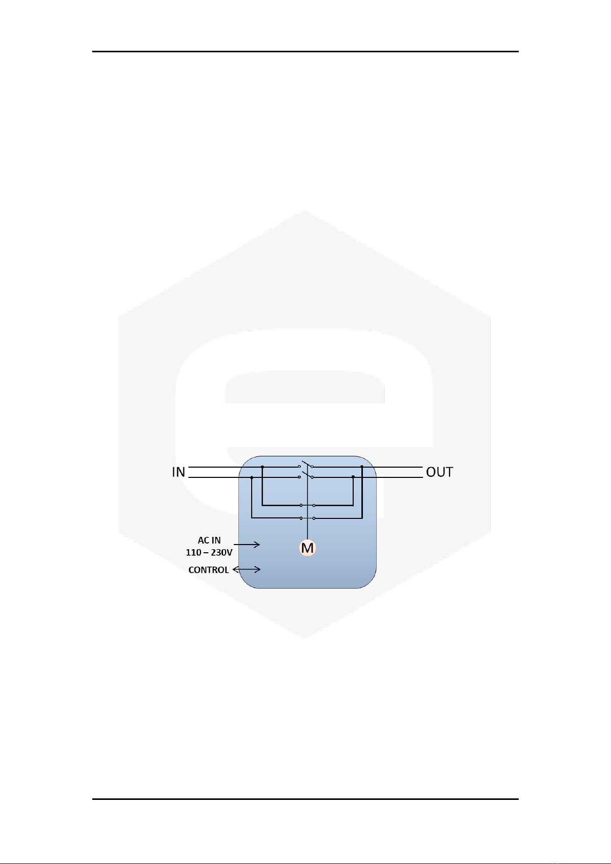
1.1 POLARITY INVERTER OVERVIEW ....................................................................9
1.2 SYSTEM PARTS .............................................................................................11
WPOLINV200XA .....................................................................................11
WPOLINV400XA / WPOLINV600XA......................................................13
2. INSTALLATION...............................................................................................16
2.1 PREPARATION FOR USE.................................................................................16
2.2 INITIAL INSPECTION ......................................................................................16
2.3 MOUNTING....................................................................................................17
2.4 AC INPUT POWER CONNECTIONS..................................................................17
AC Input Requirements............................................................................17
AC Input Cord..........................................................................................18
2.5 CONNECTIONS...............................................................................................19
Power Connectors....................................................................................21
2.5.1.1 WPOLINV200XA .................................................................................21
2.5.1.2 WPOLINV400XA / WPOLINV600XA..................................................22
Control and Monitoring Connector.........................................................23
Earth connection......................................................................................24
3. TECHNICAL SPECIFICATIONS ..................................................................25
4. MECHANICAL DIMENSIONS.......................................................................26
5. CONTROL CABLE...........................................................................................28
6. NGPS CONFIGURATION...............................................................................29

Polarity Inverters –User’s Manual
5
Document
Revision
Date
Comment
1.0
December 11th, 2017
First Release
1.1
June 26th, 2022
Added 400/600 A models
1.2
November 22nd, 2022
Added UKCA compliance logo

Polarity Inverters –User’s Manual
6
Safety information
The following table shows the general environmental requirements for a correct
operation of referred instruments in this User’s Manual:
Environmental Conditions
Requirements
Environment
Indoor Use
Operating Temperature
0°C to 45°C
Operating Humidity
20% to 80% RH (non-condensing)
Altitude
Up to 2000 m
Pollution degree
2
Overvoltage Category
II
Storage Temperature
-10°C to 60°C
Storage Humidity
5% to 90% RH (non-condensing)
The following symbols are used within this manual or are reported in the box
and along this manual:
•Caution: Documentation must be consulted in all cases where this
symbol is marked
•0 Off (Power)
•I On (Power)
•The WARNING sign denotes a hazard. An attention
to a procedure is called. Not following procedure correctly could result in
personal injury. AWARNING sign should not be skipped and all indicated
conditions must be fully understood and met.
•The CAUTION sign denotes a hazard. An attention to a
procedure is called. Not following procedure correctly could result in
damage to the equipment. Do not proceed beyond a CAUTION sign until all
indicated conditions are fully understood and met.
WARNING
CAUTION

Polarity Inverters –User’s Manual
7
CAEN ELS will repair or replace any product within the guarantee period if the
Guarantor declares that the product is defective due to workmanship or materials and
has not been caused by mishandling, negligence on behalf of the User, accident or any
abnormal conditions or operations.
Please read carefully the manual before operating any part of the instrument
Do NOT open the boxes
CAEN ELS s.r.l. declines all responsibility for damages or injuries caused by an
improper use of the Modules due to negligence on behalf of the User. It is strongly
recommended to read thoroughly this User's Manual before any kind of operation.
CAEN ELS s.r.l. reserves the right to change partially or entirely the contents of this
Manual at any time and without giving any notice.
Disposal of the Product
The product must never be dumped in the Municipal Waste. Please check your local
regulations for disposal of electronics products.
WARNING

Polarity Inverters –User’s Manual
8
•Do not use this product in any manner not specified by
the manufacturer. The protective features of this
product may be impaired if it is used in a manner not
specified in this manual.
•Do not use the device if it is damaged. Before you use
the device, inspect the instrument for possible cracks or
breaks before each use.
•Do not operate the device around explosives gas, vapor
or dust.
•Always use the device with the cables provided.
•Turn off the device before establishing any connection.
•Do not operate the device with the cover removed or
loosened.
•Do not install substitute parts or perform any
unauthorized modification to the product.
•Return the product to the manufacturer for service and
repair to ensure that safety features are maintained
WARNING

Polarity Inverters –User’s Manual
9
1.Introduction
This chapter describes the general characteristics and main features of the
Polarity Inverters WPOLINV200XA, WPOLINV400XA and WPOLINV600XA.
1.1 Polarity Inverter Overview
Extreme reliability and easiness of configuration and maintenance are the key
features of these polarity inverters.
These polarity inverters are able to reverse currents up to 630 A and so they
represent the perfect fit for the CAEN ELS NGPS unipolar power supplies, both in single
or paralleled configurations.
Each polarity inverter fits in a single 19”6U crate and it can be controlled via
dry contacts while providing to the user information about the correct working of the
system and the selected polarity.
Figure 1: Schematic of the unit.
Polarity inversion is achieved with a linear motor acting as commutator, this
avoiding any possible problem even in case of e.g. black out –which represents an
issue if inversion is obtained via relays-based commutators.
Figure 1 represents the schematic operation of the unit. A linear motor is
responsible for the polarity switching, e.g. in Figure 1 the selected polarity is reversed.

Polarity Inverters –User’s Manual
10
These polarity inverters have the following ratings listed in Table 1:
Model
Description
Maximum Voltage
Maximum Current
WPOLINV200XA
200 A Polarity Inverter
250 V
200 A
WPOLINV400XA
420 A Polarity Inverter
250 V
420 A
WPOLINV600XA
630 A Polarity Inverter
250 V
630 A
Table 1: Main ratings of the polarity inverters.
If the rear power connections of the Polarity Inverter are
accessible, IN and OUT connections result in HAZARDOUS
LIVE parts and must be isolated or confined following local
regulations.
If the Maximum Voltage level is below 70 VDC further
isolations are not required.
All these polarity inverters are already supplied with the signal cable that allows
connecting them directly to an NGPS power supply.
WARNING

Polarity Inverters –User’s Manual
11
1.2 System Parts
WPOLINV200XA
The WPOLINV200XA is housed in a 6U –19” crate (Figure 2).
Figure 2: Front WPOLINV200XA panel.
The main parts on the front panel of the WPOLINV200XA polarity inverter are
listed below:
1-Four fuses are installed, two of them connected to the AC mains and the
other ones to the rectified 24V mains. Fuses are 10.3 x 38 mm and value:
•Mains 220 VAC -> 2 A T 500 V CH10 (1421002)
•Mains 24 VDC -> 2 A T 500 V CH10 (1421006)
2- MAIN PRESENCE - if ON it signals the presence of the Mains VAC;
3-DIRECT polarity - if ON it signals that the polarity is direct;
4-REVERSE polarity - if ON it signals that the polarity is reversed;
5–COUNTER - it indicates the number of times the polarity has been
reversed.
1
2
3
4
5

Polarity Inverters –User’s Manual
12
The rear panel of the polarity inverter contains the parts related to the control
and monitoring of the unit, see Figure 3: Rear WPOLINV200XA panel.
Figure 3: Rear WPOLINV200XA panel.
The main parts on the rear panel of the WPOLINV200XA polarity inverter are
listed below:
6- POWER CABLES from the power unit have to be connected to the DC-IN and
the load to DC-OUT. DC-IN left connector corresponds to DC-OUT left
connector in case of direct polarity, otherwise it corresponds to DC-OUT
right connector. The same is true for DC-IN right connector, which
corresponds to DC-OUT right one in case of direct polarity;
7 - CONTROL AND MONITORING connector (C1);
8- EARTH stud connection;
9- AC Mains connector with its corresponding ON/OFF button and Fuse. Fuse
must be 5 x 20 mm, 5 A T 250 V.
6
7
9
8

Polarity Inverters –User’s Manual
13
WPOLINV400XA / WPOLINV600XA
The WPOLINV400XA/600XA is housed in a 6U –19” (Figure 4: Front
WPOLINV400XA/600XA panel.).
Figure 4: Front WPOLINV400XA/600XA panel.
The main parts on the front panel of the WPOLINV400XA/600XA polarity
inverter models are listed below:
1-Four fuses are installed, two of them connected to the AC mains and the
other ones to the rectified 24V mains. Fuses are 10.3 x 38 mm and value:
•Mains 220 VAC -> 2 A T 500 V CH10 (1421002)
•Mains 24 VDC -> 2 A T 500 V CH10 (1421006)
2- MAIN PRESENCE - if ON it signals the presence of the Mains;
3-DIRECT polarity - if ON it signals that the polarity is direct;
4-REVERSE polarity - if ON it signals that the polarity is reversed;
5–COUNTER - it indicates the number of times the polarity has been
reversed.
1
2
3
4
5

Polarity Inverters –User’s Manual
14
The WPOLINV400XA/600XA polarity inverter models are delivered with a cover,
shown in Error! Not a valid bookmark self-reference., to protect the user from
accidental contacts on the DC busbars (see Figure 6:Rear WPOLINV400XA/600XA panel
without cover on the DC busbars.) during the normal operation.
Figure 5: Rear WPOLINV400XA/600XA panel with the cover on the DC busbars.
To get access to the underlaying DC busbars, the six screwcaps indicated by the red
arrows in Figure 5: Rear WPOLINV400XA/600XA panel with the cover on the DC busbars.
must be removed from the rear panel.

Polarity Inverters –User’s Manual
15
The rear panel without the cover is shown in Figure 6:Rear WPOLINV400XA/600XA
panel without cover on the DC busbars..
Figure 6: Rear WPOLINV400XA/600XA panel without cover on the DC busbars.
The main parts on the rear panel of the WPOLINV400XA/600XA polarity
inverter models are listed below:
6- POWER CABLES from the power unit have to be connected to the DC-IN and
the load to DC-OUT. DC-IN left bar corresponds to DC-OUT left bar in case
of direct polarity, otherwise it corresponds to DC-OUT right bar. The same
is true for DC-IN right bar, which corresponds to the DC-OUT right one in
case of direct polarity;
7 - CONTROL AND MONITORING connector (C1);
8- EARTH stud connection;
9- AC Mains connector with its corresponding ON/OFF button and Fuse. Fuse
must be 5 x 20 mm, 5 A T 250 V.
6
7
9
8

Polarity Inverters –User’s Manual
16
2.Installation
Please read carefully this general safety and installation information before
using the product.
2.1 Preparation for Use
In order to get ready, the polarity inverter must be connected to an appropriate
source. The source voltage should be within the polarity inverter specification. Do not
apply power before reading, Secs. 2.2,2.3, 2.4 and 2.5.
Table 2 describes the basic setup procedure: follow the instructions in the listed
sequence to prepare the polarity inverter for use.
Step
Checklist
Description
1
Initial inspection
Physical inspection of the polarity inverter
2
Mounting
Installing the polarity inverter
3
Connections
Carry out the different connections required
4
AC Input Power Connection
Connect the polarity inverter to the AC source
5
First switch-on
Switch-on checkout procedure
Table 2: Installation procedure checklist.
2.2 Initial Inspection
Prior to shipment, the polarity inverter has been inspected and found free of
mechanical or electrical defects. Upon unpacking of the unit, inspect for any damage
which may have occurred in transit.
The inspection should confirm that there is no exterior damage to the polarity
inverter such as broken connectors and that the mechanic parts are not scratched or
cracked. Keep all packing material until the inspection has been completed. If damage
is detected, compile the RMA form available to the CAEN ELS web site.

Polarity Inverters –User’s Manual
17
2.3 Mounting
The polarity inverter is designed to fit in a standard 19” equipment rack.
Always use L-shelves to correctly sustain the
polarity inverter.
2.4 AC Input Power Connections
The AC line input connector on the rear panel is the same for all the polarity
inverter models, namely an IEC C14 socket [shown in Figure 7(a)].
Figure 7: AC Power Line input socket of the polarity inverter.
The polarity inverter comes with an IEC C13 power cable [Figure 7(b)].
AC Input Requirements
The units are designed for universal AC input range, indeed it can operate with
an input voltage value ranging from 110 V to 230 V and an input frequency ranging
from 47 Hz to 63 Hz. Installation Category shall be CAT II, so maximum impulse voltage
on the network mains must be below 250 V.
CAUTION

Polarity Inverters –User’s Manual
18
AC Input Cord
The polarity inverters are directly shipped with the corresponding power cord
(suitable for the destination country of the purchase). Polarity Inverter side connector
is a standard IEC C14 plug for all the models. Wire size for detachable power supply
cord, shall be at least 0.75 mm2. Wire size for fix installation shall be at least 1 mm2.
There is a potential shock hazard if the chassis is not
connected to an electrical safety ground via the safety
ground in the AC input connector or the EARTH stud!
WARNING

Polarity Inverters –User’s Manual
19
2.5 Connections
Turn off the input power before making or changing any rear
panel connection. Ensure that all connections are securely
tightened before applying power.
The connections mentioned in Section 1.2 are hereafter shown again.
WPOLINV200XA
Figure 8: Rear panel of the WPOLINV200XA model.
The main parts on the rear panel of the WPOLINV200XA polarity inverter are listed
below (see Figure 8: Rear panel of the WPOLINV200XA model.):
6 - POWER CABLES from the power unit have to be connected to the DC-IN and
the load to DC-OUT. DC-IN left connector corresponds to DC-OUT left
connector in case of direct polarity, otherwise it corresponds to DC-OUT
right connector. The same is true for DC-IN right connector, which
corresponds to DC-OUT right one if the polarity is direct;
7 - CONTROL AND MONITORING connector (C1);
8- EARTH stud connection.
WARNING
6
7
8

Polarity Inverters –User’s Manual
20
WPOLINV400XA/600XA
Figure 9: Rear panel of WPOLINV400XA/600XA models.
The main parts on the rear panel of the WPOLINV400XA/600XA polarity inverter
models are listed below (see Figure 9: Rear panel of WPOLINV400XA/600XA models.):
6- POWER CABLES from the power unit have to be connected to the DC-IN and
the load to DC-OUT. DC-IN left bar corresponds to DC-OUT left bar in case
of direct polarity, otherwise it corresponds to DC-OUT right bar. The same
is true for DC-IN right bar, which corresponds to DC-OUT right one if the
polarity is direct;
7 - CONTROL AND MONITORING connector (C1);
8- EARTH stud connection.
6
7
8
This manual suits for next models
2
Table of contents
Popular Inverter manuals by other brands

DUROMAX
DUROMAX DUAL FUEL XP13000EH quick start guide

SolaX Power
SolaX Power X3-FORTH Series user manual

World Video Sales
World Video Sales MicroImage Video Systems PG314N manual

Sungrow
Sungrow SH5.0RT Quick installation guide

Rinnai
Rinnai EVT20A Operation & installation manual

Baker Hughes
Baker Hughes 2000 Series Installation and operation manual