10
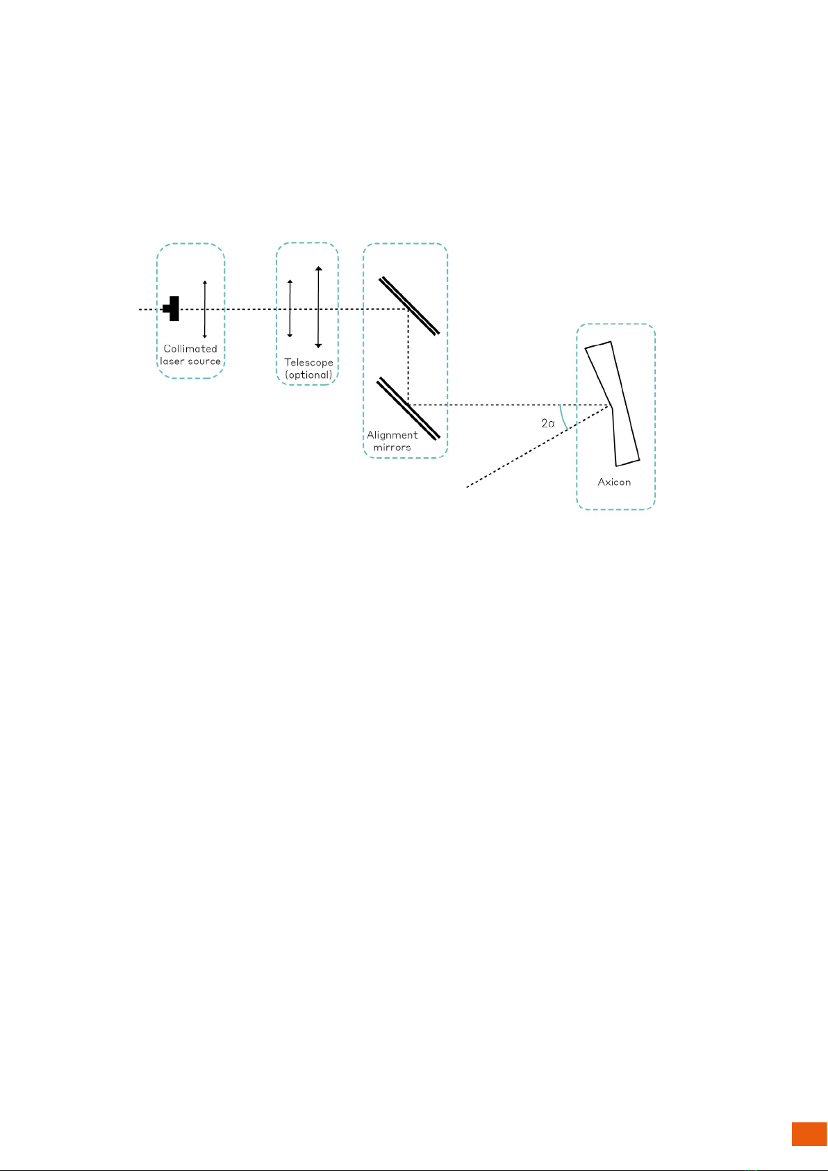
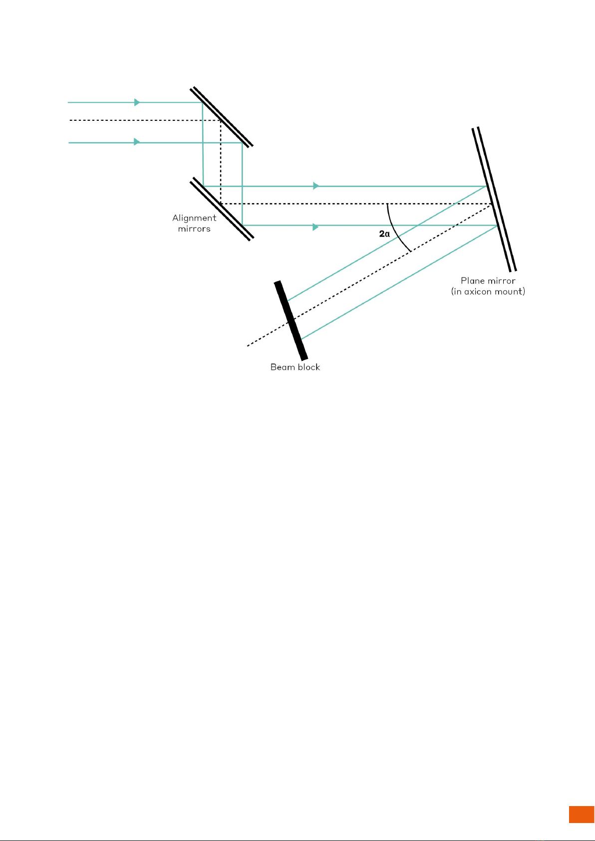
Axicon alignment
When the mirror in the axicon mount is correctly positioned,
replace it with the axicon. The axicon’s substrate has a lat
edge that can be used to achieve the correct rotational position.
This lat edge should be placed at the top.
[
Axicon’s
lat edge
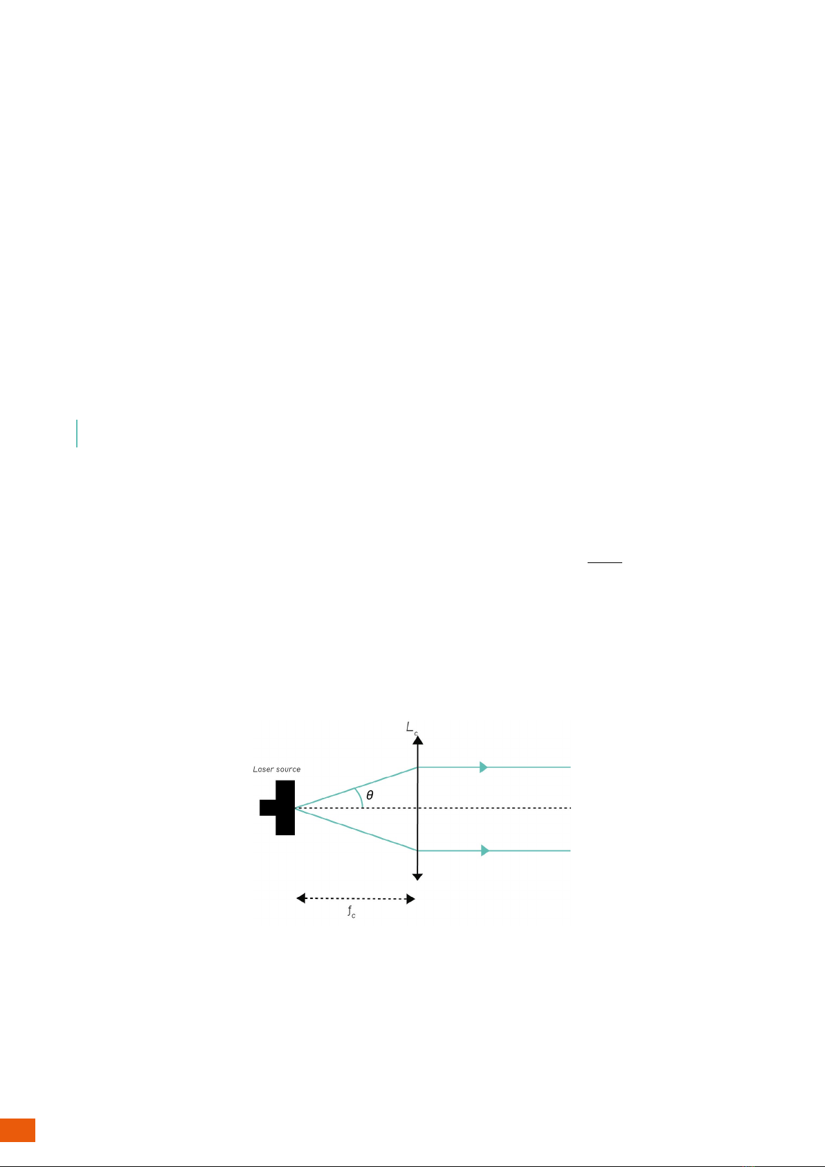
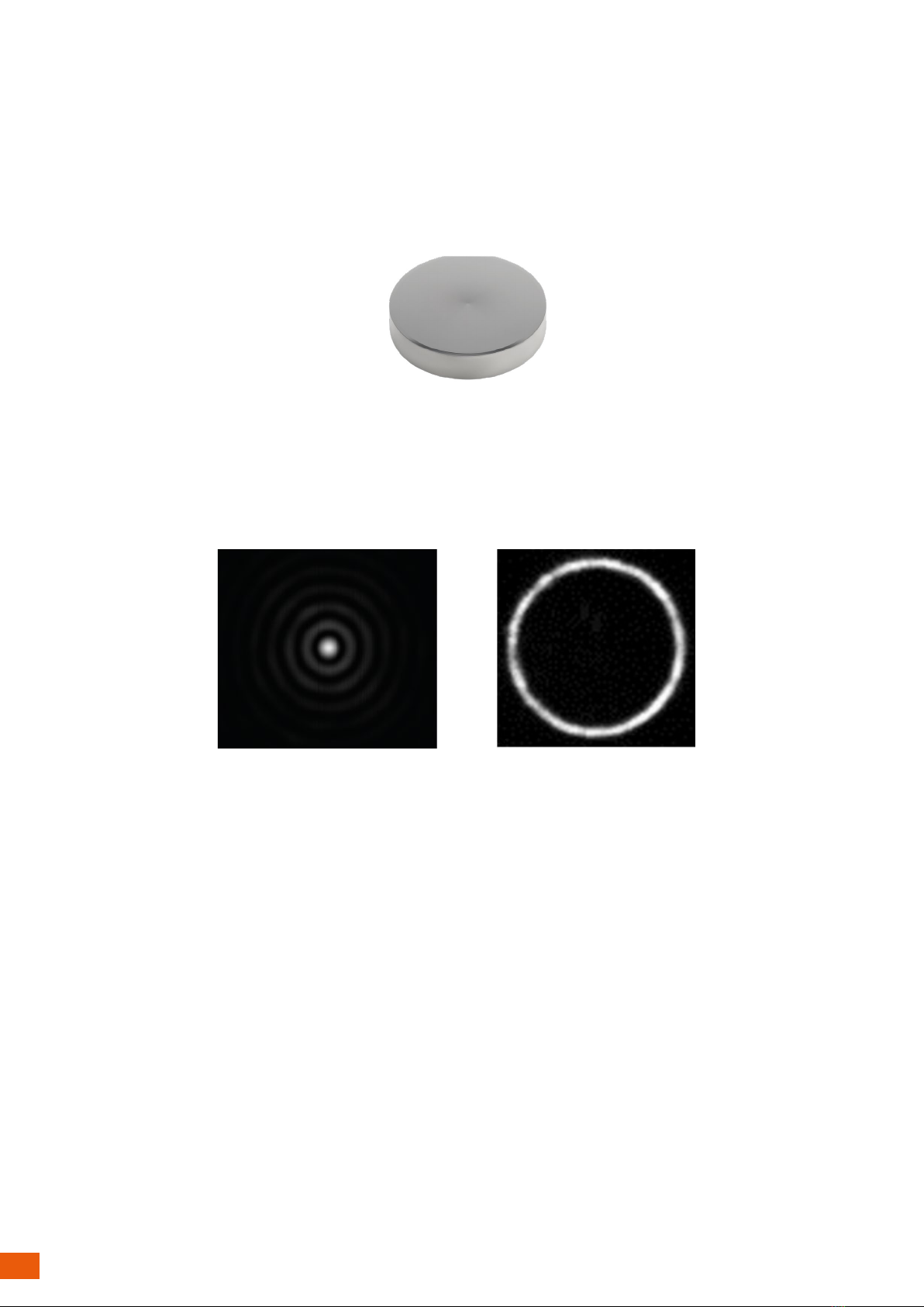
With the IR card, scan the beam path to see where the Bessel beam and the ring-shaped beam are generated:
Bessel beam in near ield (left), ring-shaped beam in far ield (right)
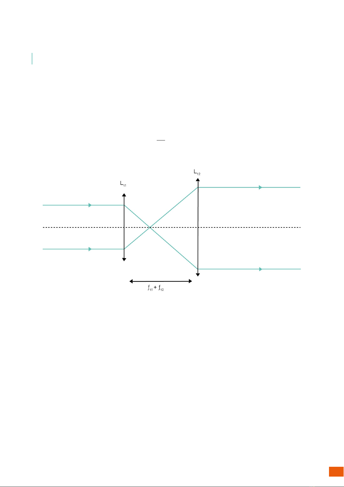
Here, the two mirrors alignment technique can be used where
the irst mirror is adjusted to ensure correct positioning in
near ield (i.e. that the beam exiting the second mirror is at the
same height as the axicon center and that the beam is at the
correct lateral spot just after this second mirror). The second
mirror is then adjusted to aim at the center of the axicon. By
doing so, the beam position right behind the second mirror is
modiied and needs to be adjusted through an iterative process,
alternating between alignment of the irst and second mirror.
From a visual perspective, you should see a circular beam behind
the axicon with a homogeneous intensity, except at the center
where it brightens (corresponding to the central spot of the
Bessel beam). This beam will propagate over tens of centimetres
(depending on the axicon and system in use) and slowly evolve
into a donut shape.
A irst alignment can be performed visually by observing if the
beam in near ield is circular and if its bright spot is centered. In
far ield, you must verify that the ring is circular.
By adjusting the two mirrors placed before the axicon, the user
ensures the injection angle and position are correct. The irst
mirror allows adjustment in near ield whilst the second one
allows correction in far ield.
As mentioned before, this will be an iterative process, going
back and forth between aligning the irst and second mirror.