CALECTRO CFA-24V User manual

Calectro AB Phone: +46 31-69 53 00 info@calectro.com www.calectro.com
CFA-24V / CFA-230V INSTALLATION INSTRUCTIONS
ENGLISH
Electronic freeze protection alarm with
warming function, double relays and digital
display.
CFA-24V Freeze protection alarm 24V AC
CFA-230V Freeze protection alarm 230V AC
WARNING: IMPORTANT
INFORMATION
CONCERNING
ELECTRICAL SAFETY
AND ENVIRONMENT
This product may contain dangerous volt-
age. The product’s housing is not meant
to be removed. At a supply voltage of
230V AC the product must be powered
via a nearby mains switch labelled “Mains
Switch for CFA freeze protection alarm”.
The product’s relay switch can be powered
with 230V. The power must be switched off
during maintenance. The product is intend-
ed for indoor use only. The product must
not be subjected to liquid or moisture. The
product’s exterior can be cleaned using
a damp cloth. The product is intended for
mounting on a DIN rail / Norm enclosure in
a protected space.
!
INDEX
1. Technical Data
2. Function
3. Use
4. Installation
5. Maintenance
6. Buttons and menu system
7. Selection of temperature sensor type –
factory setting: Pt1000
8. Setting the setpoint
9. Resetting the alarm
10. Fine-adjustment of the temperature
measurement
11. Display example
12. Error codes and temperature / Ohms table
13. Figures
14. Connection examples for CFA-24V and
CFA-230V
15. Menu system – monitoring / shortcut menu
1. TECHNICAL DATA
Supply voltage
CFA-24V: 24V AC ±10%,
CFA-230V: 230V AC ±10% 50-60 Hz
Relay outputs: 250V ~5 A resistive
loading, potential-free
changeover
Power consumption: 4W
Output signal: 0-10V or 10-0V
Temperature range
Alarm temperature: 0 to 20°C
Warming function: 5 to 50°C
Ambient temp.: 0 to +40°C
Selectable
temperature sensor: Pt1000 (factory setting),
NTC (Calectro type: 22/
33/44/55/99), Pt100,
Ni1000, and PTC
(Calectro type: 95)
Mounting: DIN rail, Norm enclosure
Dimensions WxHxD: 52.5 x 86 x 59 mm
Weight: 240 gram
Protection class: IP20
2. FUNCTION
CFA is connected to a temperature sensor that
measures the water temperature in the heating
coil. The water temperature in the heating coil is
normally regulated by another regulator/DUC with the
control signal (0-10or 10-0V) connected viaCFAtothe
control valve. If the water temperature in the coil
drops without any response from the regulator /
DUC, CFA starts regulating the control valve.
When the water temperature in the coil drops below
the pre-set alarm temperature, both relay outlets fall
(normally activated).
Daytime mode
During daytime the control signal regulates with a
proportional band of 4°C. The control signal begins
regulating when the temperature drops to the pre-set
alarm temperature plus one degree plus the
proportional band.
Example 1: Alarm temperature = 5°C: The control
signal begins regulating at 10°C (5+1+4).
Example 2: Alarm temperature = 5°C: At or under
6°C the control signal is 100%.
Temperature
Control signal
Alarm temperature
0% 1°C 4°C p-band
100%
DAYTIME MODE
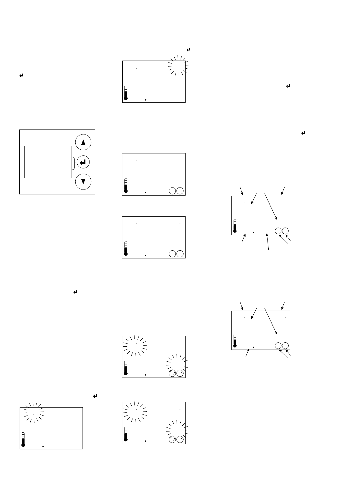
Daytime mode is activated by a short circuit
between terminals 9 and 12. During daytime
mode, D4 is shown in the top right-hand corner
of the display and DI (under °C) is lit to indicate
that the digital input (DI) is short-circuited.
Menu
°
C
DI
Night mode / warming function
During night mode (warming function) the water
temperature in the heating coil is regulated by
a setpoint that is adjustable between 5 and 50°
(proportional band: 10°C).
Temperature
Control signal
alarm temperature
0% 10°C P-band
100%
NIGHT MODE
Warming function
setpoint
Night mode is activated by cutting any jumpers
between terminals 9 and 12.
Menu
°
C
Self-test
During start-up and the replacement of
temperature sensors, CFA performs a self-test.
Three lines begin to blink at the bottom of the
display. The current temperature shows up here
on completion. Interruption on the temperature
sensor circuit shows up as Er0 on the display,
and Er1 for short circuit. Upon interruption or
short circuit, the alarm relays fall and the control
signal goes to 100%.
3. USE
CFA is an electronic freeze protection alarm with
a digital display that is used to monitor frost in
air heating systems that use water as the heat
carrier.
4. INSTALLATION
CFA is mounted on a DIN rail and is suited to
Norm enclosures.
5. MAINTENANCE
CFA requires no maintenance.
© 2020.11.20 R1.1 Calectro AB HFE656 EN
EN

The setpoint for warming function (night mode),
which is shown in the display’s top right-hand corner,
now begins to blink. Use ▲ to ▼ change to desired
value and press Enter to confirm ( ). Ready!
Enter
°
C
DI
These settings can also be changed during an alarm.
9. RESETTING THE ALARM
When the alarm triggers, the relays remain in alarm
mode until the reset button is pressed.
Freeze alarm in daytime mode
Reset
Alarm
°
C
12
DI
Freeze alarm in night mode
Reset
Alarm
°
C
12
If the alarm mode returns to normal temperature
when the Reset button is pressed, the relays are
reset and the middle button returns to the Menu
function.
If the alarm is still triggered after the Reset button is
pressed, the relays have not been reset and Alarm
and Reset blink three times. The middle button then
returns to the Menu function for 20 seconds to allow
settings to be changed in the menu system before
returning to Reset.
Reset depressed in alarm mode (daytime mode)
Reset
Alarm
°
C
12
DI
Reset depressed in alarm mode (night mode)
Reset
Alarm
°
C
12
6. BUTTONS AND MENU SYSTEM
▲ = Step up in the menu / increase value - Keep
the button depressed and the setpoint counts up
rapidly.
▼ = Step down in the menu / decrease value -
Keep the button depressed and the setpoint
counts down rapidly.
= Is a multifunction button, the current status*
of which is shown on the display next to the but-
ton.
* Middle button functions:
• Exit Menu = Exit the menu / Save setting
• Menu = Enter the menu or select application
• Enter = Confirm setting
• Reset = Resets the relay after an alarm.
Menu
Enter
Reset
Exit
The menu system comprises of the following
sub-menus:
1. Selection of temperature sensor
2. Fine-adjustment of the temperature
measurement
4. Selection of output signal: 0-10 or 10-0V
5. Exit the menu system
7. SELECTION OF TEMPERATURE
SENSOR
CFA can be connected to a range of temperature
sensors: Pt100, Pt1000, Ni1000 plus Calectros
NTC and PTC sensors in the ETF series. Pt1000
is a factory set sensor.
2. Press the Menu button ( ) to enter the
menu system
3. The current type of temperature sensor is
shown
4. Press Menu-Enter to change the tempera-
ture sensor type
5. The current sensor type begins to blink and
you can now use the arrow buttons to select
another sensor type. Press Enter to confirm
your selection.
6. Use the arrow keys and confirm Exit-Menu
to exit
8. SETTING THE ALARM TEMPERATURE
AND HEAT RETENSION SETPOINT
To change the alarm temperature, press ▲ or
▼ to the desired value. The alarm temperature,
which is shown in the top left-hand corner, blinks
during setting. Press Enter to confirm ( ).
Enter
°
C
DI
The alarm temperature and warming function
setpoint can always be adjusted, even during
alarm mode. See 8.
10. FINE ADJUSTMENT OF THE
TEMPERATURE MEASUREMENT
The temperature measurement in CFA can be
adjusted if necessary. Range: -3°C to +3°C in
steps of 0.1°C.
1. Press the Menu button ( ) to access the
menu system
2. Press the arrow key until ‘Adj’ shows on the
display
3. Press Menu-Enter to adjust
4. The current compensation and temperature
starts to blink and you can now adjust the
compensation using the arrow keys. Press
Enter to confirm your selection ( ).
5. Use the arrow keys and confirm Exit-Menu
to exit
11. DISPLAY EXAMPLE
The below example shows CFA in daytime
mode. The freeze alarm has triggered.
Reset
Alarm
°
C
12
DI
Current temperature
Digital inlet
short circuited = daytime mode
Daytime mode: 4°C
p-band
Both relays have
been deactivated =
alarm mode
Alarm temperature
Alarm mode
The below example shows CFA in night mode
/ warming function. The freeze alarm has trig-
gered.
Reset
Alarm
°
C
12
Current temperature
Night mode/
warming function
Both relays have
been deactivated =
alarm mode
Alarm temperature
Alarm mode
12. ERROR CODES
CFA monitors the temperature sensor so that a
short circuit or interruption on the sensor circuit
triggers the alarm and sets the control signal at
100%.
Er0 Interruption on the sensor input
Er1 Short circuit on the sensor input
Er2 Temperature sensor out of range

Temperature / Ohm table
Sensor type Temperature Ohm
Pt1000 0°C
20°C
40°C
1000
1078
1156
Pt 100 0°C
20°C
40°C
100
107. 8
115.6
Ni1000 0°C
20°C
40°C
1000
1090.7
1185.7
NTC
(Calectro type
22/33/44/55/99)
0°C
20°C
40°C
37942
14871
6539
PTC
(Calectro type 95)
0°C
20°C
40°C
1631
1915
2226
13. FIGURES
FIG. 1
45
1 2 3 4 5 6 7 8
9 10 11 12 13 14 15 16
60 86
52,5/3 mod.
54
29 19 11
59
FIG. 2 (CFA-24V)
The relay outputs are shown in alarm/
no power on condition. Max 5A, 250V.
24V AC
24V AC
Relay 1
Relay 1
Relay 1
Relay 2
Relay 2
Relay 2
1 2
L N
3 4 5 6 7 8
9 10 11 12 13 14 15 16
GND
Temp. sensor
Temp. sensor
Digital in
Analogue out
Analogue in
Not used
Not used
RC/
DUC
FIG. 3 (CFA-230V)
The relay outputs are shown in alarm/
no power on condition. Max 5A, 250V.
230V AC
230V AC
Relay 1
Relay 1
Relay 1
Relay 2
Relay 2
Relay 2
1 2
L N
3 4 5 6 7 8
9 10 11 12 13 14 15 16
GND
Temp. sensor
Temp. sensor
Digital in
Analogue out
Analogue in
Not used
Not used
RC/
DUC
14. CONNECTION EXAMPLE FOR CFA-24V AND
CFA-230V
The relays are shown in alarm/ no power on
condition.
1 2
24V AC
The relays are shown in a de-energised state
3 4 5 6 7 8
Relay 1 Relay 2
1 2
230V AC
The relays are shown in a de-energised state
3 4 5 6 7 8
Relay 1 Relay 2

Calectro AB Phone: +46 31-69 53 00 info@calectro.com www.calectro.com
15. MENU SYSTEM – MONITORING
Menu
Enter
Pt1000
Menu
Enter
Adj
Enter
Pt1000 Enter
Pt100 Enter
Enter
Enter
Menu
Exit
P TC Enter
NTC
Save settings and return to the normal display position through Exit-Menu.
Enter
Select the desired output signal: 0-10V or 10-0V. Confirm with Enter.
Enter
Ni 1000
°
C
°
C
Adj
Menu
Enter
Enter
Menu
°
C
DI
Menu
°
C
DI
Press Menu to access the Menu System.
Navigate between the submenus using the arrow
keys and select sub-menu with Menu-Enter.
Select the type of temperature sensor. Navigate between the different types and confirm with Enter.
If necessary the temperature measurement may be fine-tuned (-3.0 to +3.0°C). Confirm with Enter.
This manual suits for next models
1
Other CALECTRO Security System manuals