Calistair C300 User manual

Invented in France
Made in Germany
CALISTAIR C300
QUICK START GUIDE
www.calistair-C300.com
Email: kontakt@calistair.com
Science for healthy air.

All representations and pictures, © Calistair, September 2020
SAFETY INSTRUCTIONS
• Read the translation of the original operating instructions carefully before commissioning
and keep them in a safe place.
• Improper use can damage the device and cause personal injury.
• Operate the device only for the intended purpose and under the permissible conditions.

3
1.1. YOUR PERSONAL AIR DECONTAMINATION PLANT
Congratulations!
With the Calistair C300 you have purchased a high-performance system that uses the innovative
Calistair Technology to destroy microorganisms, gases and volatile organic compounds. It is able
to clean your room air of almost all air pollutants and thus make a considerable contribution to
your general well-being.
1. PRODUCT OVERVIEW
1.2. MODE OF OPERATION
The Calistair C300 is a decontamination plant with a highly effective technology for air
decontamination.
On the surface of the specially coated reactor honeycomb plates inside the device, UVC radiation
from the lamps stimulates a catalytic reaction. This reaction causes organic compounds such
as harmful gases, bacteria, viruses, fungal spores and unpleasant odorous substances to be
decomposed at molecular level and be thus neutralised.
This technology ensures a very high performance even with pollutants where conventional lter
air puriers or pure UV air clariers fail. For example the elimination of formaldehyde from the
breathing air, which many pieces of furniture or oor coverings release over time.
The prelter on the underside lters coarse particles from the air, such as house dust, uff or
hair. This means that the interior of the device remains largely free of coarse dust.
With the high-performance lter, the room air can also be cleaned of ne dusts, allergens and
mineral air pollutants such as soot particles.
For more information on Calistair technology and cleaning performance,
please visit www.calistair-C300.com

4
1.3. SYSTEM COMPONENTS
Housing cover
Rear air intake
Fixed castors
Prelter insert
UVC uorescent tubes
High-performance lter (HEPA lter)
Lateral air intake
Fan
Filter drawer
Housing
Adjustment wheel
Power switch
Reactor honeycomb plates
Power connection
Air outlet grid

5
1.5. LOCATION SELECTION
When selecting a suitable location, consider the following factors for an optimal result to
improve air quality:
• The device should be at least 20 cm away from the wall or other objects on all sides so that
the air intake is not disturbed.
• The device should have at least 50 cm free space at the top so that the air can be blown off
undisturbed.
• The system should be placed on a stable, dry and level surface in such a way that neither
the device nor the power cable presents a tripping hazard.
• The control panel and housing cover should be easily accessible.
• The air should be able to circulate more or less unhindered in the room.
1.4. INDOOR AIR QUALITY
Air quality is an essential factor for general well-being and can have a major impact on health,
power of concentration and performance. An air purier can signicantly improve indoor air
quality, but should not be the only measure to do so. In principle, the following additional
measures are recommended to improve air quality:
• Always ensure that there is a sufcient supply of fresh air so that there is enough oxygen
(O2) in the air you breathe and that the carbon dioxide concentration (CO2) does not become
too high, as this can lead to fatigue and impair the ability to concentrate.
• If possible, ensure that the air humidity is between 40 % and 60 %, as excessively dry air
can lead to irritated mucous membranes and eyes, which among other things increases
susceptibility to infection.
• Eliminate or reduce possible causes of air pollution or pollutants as much as possible.
• Ensure that the measures for fresh air supply and air treatment are appropriate for the size
of the room. It may be necessary to use several devices.

6
2. COMMISSIONING
Fig. 1
Fig. 2
Fig. 3
2.1. USE
Before commissioning, make sure that the
device is completely assembled and free of
damage.
A. Place device at a suitable location.
B. Connect power cable to device (Fig. 1).
C. Connect power plug to a grounded socket.
D. Switch on device (Fig. 2).
E. Select air ow via adjustment wheel
(Fig. 3).
Use the power switch to turn off the
device completely when not in use,
otherwise the UVC uorescent tubes will
continue to glow, reducing their life.
NOTE
The air performance of the device
depends, among other things, on the
degree of saturation of the lters and
can therefore decrease over time. It is
therefore essential that you observe the
necessary maintenance intervals.

7
3.1. CLEANING THE DEVICE
Only clean the outside of the device if necessary. Observe the following instructions for external
cleaning:
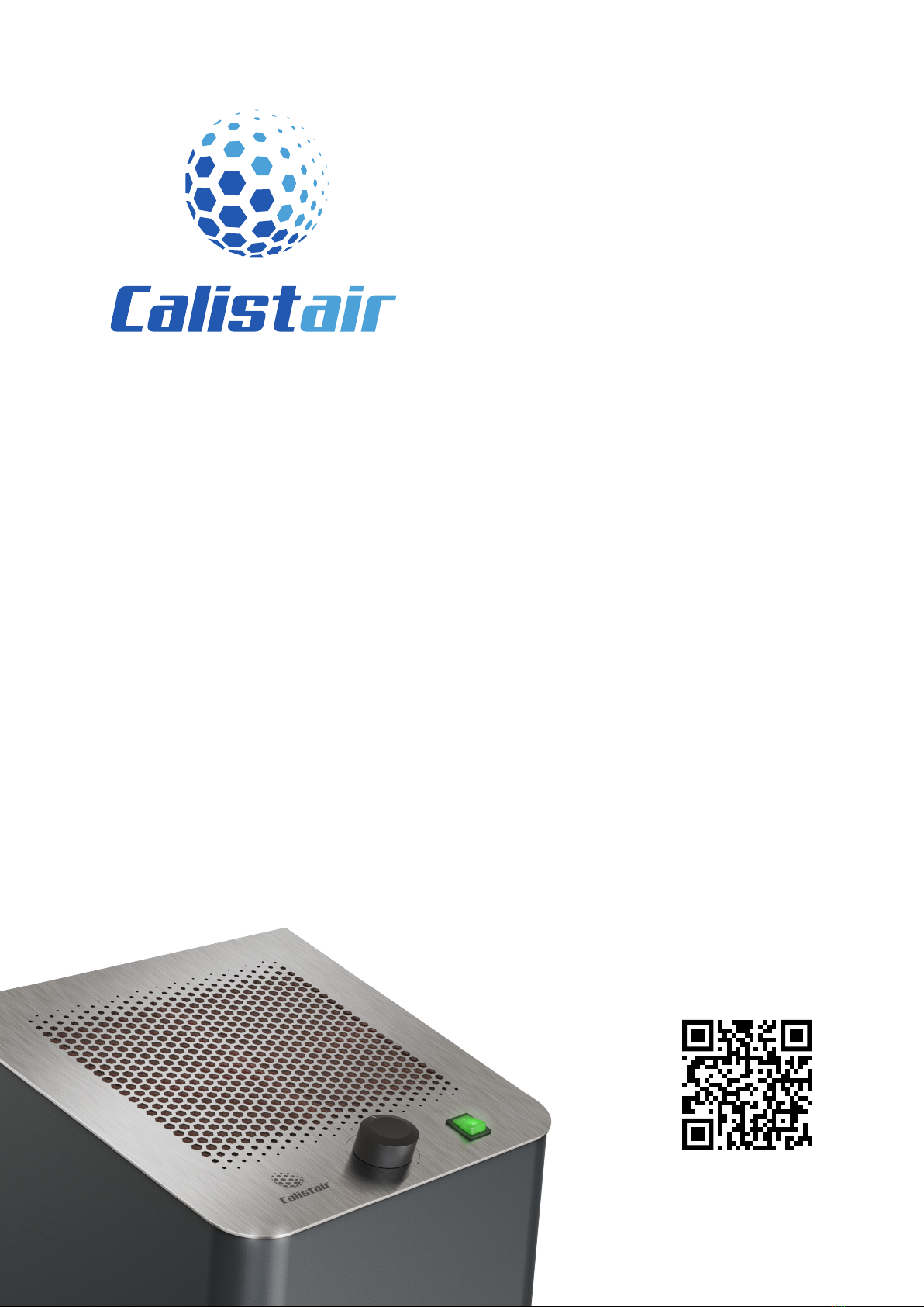
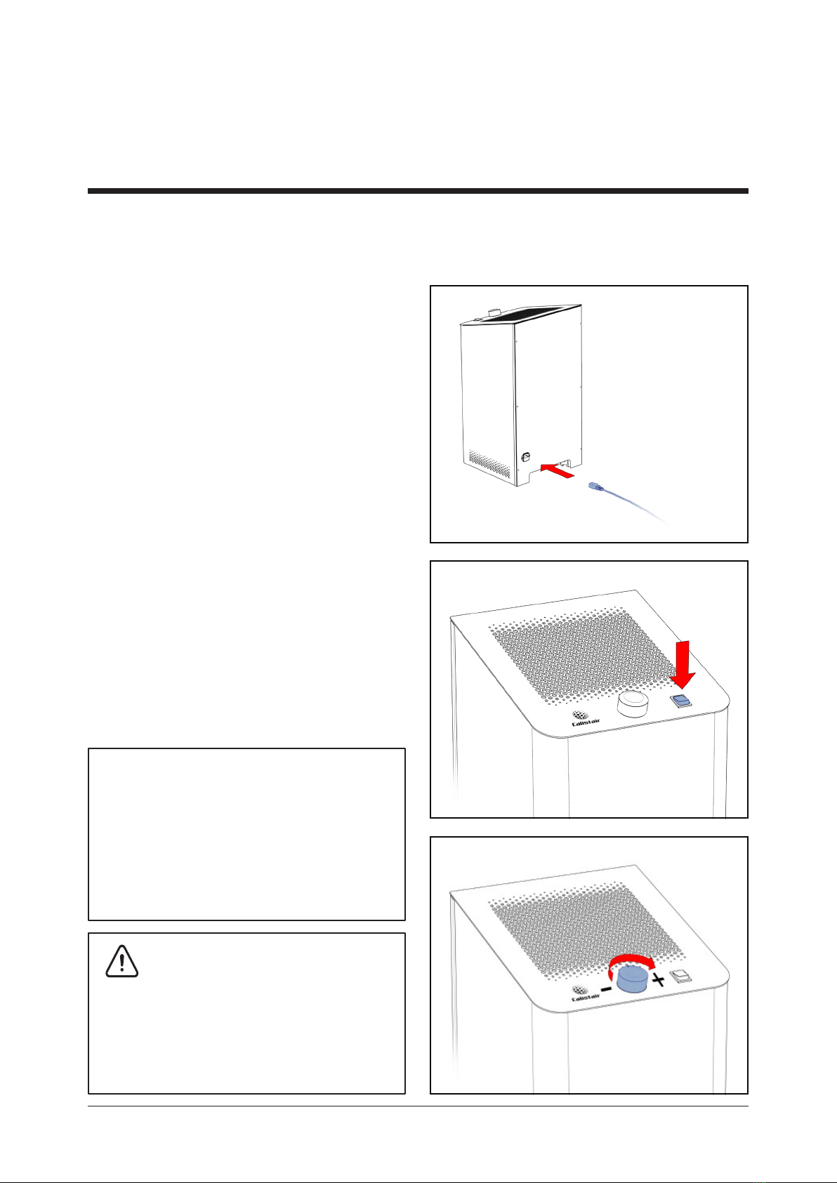
• Switch off the device and unplug the power plug from the socket.
• Only use a dry or minimally moistened cloth.
• Do not use aggressive or abrasive cleaning agents, since this can damage the surfaces.
• Always make sure that no moisture enters the device.
Due to the prelter and the sterilising technology, neither cleaning nor disinfection should
normally be necessary inside.
3.2. MAINTENANCE INTERVALS
To ensure smooth operation of your device, certain wear parts must be checked at and / or
replaced at regular intervals:
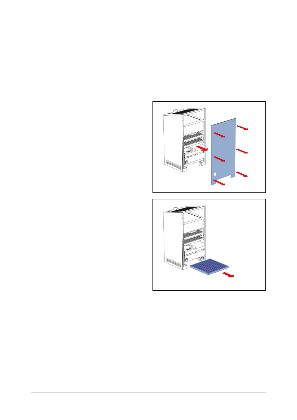
• Depending on the environment, the prelter must be checked at regular intervals. Therefore,
check the degree of saturation of the prelter after approx. 3 months at the latest and
replace the prelter before it is completely saturated.
How quickly the prelter saturates depends among others on the following factors:
- performance level of the air purier
- amount of dust in the environment
- amount of textiles or carpets in the environment
- number of people and animals in a room
- number of air puriers in a room
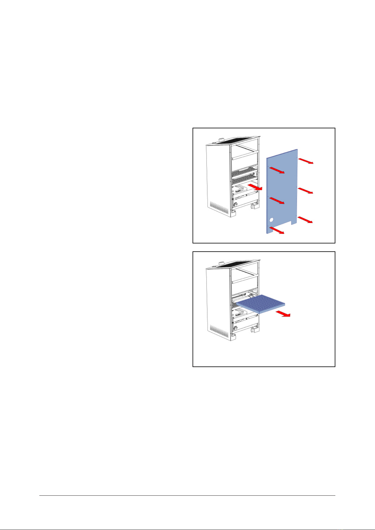
• If the device is used daily, the high-performance lter (HEPA lter) must be replaced after
approx. one year at the latest. Replace the high performance lter before it is completely
saturated.
• UVC uorescent tubes are subject to natural ageing. If used daily, they must be replaced
after one year at the latest, otherwise the germicidal effect is no longer guaranteed, even if
the UVC uorescent tubes are still visibly illuminated.
• For all maintenance work, it is recommended that you wear work gloves and a face mask for
self-protection.
3. MAINTENANCE

8
Fig. 1
Fig. 2
3.3. CHANGE PREFILTER
A. Switch off device.
B. Pull power plug.
C. Loosen screws on the housing cover with
suitable tool.
D. Remove housing cover (Fig. 1).
E. Pull the prelter insert out of the mounting
on the underside of the housing (Fig. 2).
F. Push the new prelter insert into the
mounting up to the stop.
G. Attach housing cover.
H. Check seal for correct seating.
I. Tighten screws.
Device is ready for operation.

9
Fig. 1
Fig. 2
Fig. 3
3.4. CHANGE HIGH-
PERFORMANCE FILTER
A. Switch off device.
B. Pull power plug.
C. Loosen screws on the housing cover with
suitable tool.
D. Remove housing cover (Fig. 1).
E. Pull the lter drawer forward on the metal
tab up to the stop (Fig. 2).
F. Remove lter (Fig. 3).
G. Put used the lter in a plastic bag and
seal it.
H. Place new lter on the lter drawer with
the seal facing upwards and push the lter
into the housing up to the stop.
I. Push lter drawer into the housing until it
audibly clicks into place on both sides.
J. Attach housing cover.
K. Check seal for correct seating.
L. Tighten screws.
Device is ready for operation.

10
Fig. 2
3.5. CHANGE UVC
FLUORESCENT TUBES
A. Switch off device.
B. Pull power plug.
C. Let device cool down for at least
30 minutes.
D. Loosen screws on the housing cover with
suitable tool.
E. Remove housing cover (Fig. 1).
F. Carefully pull the upper reactor honey-
comb plate out of the mounting (Fig. 2).
Fig. 1

11
Fig. 4
Fig. 3
G. Hold uorescent tube with one hand.
H. With the other hand, press the red button
on the lamp socket completely until
the UVC uorescent tube can be easily
removed upwards.
I. Remove all uorescent tubes in this way
(Fig. 3).
J. Press new UVC uorescent tubes with the
contact pins into the lamp sockets from
above until they audibly click into place
(Fig. 4).
K. Push upper reactor honeycomb plate
carefully into the mounting until it stops.
L. Attach housing cover.
M. Tighten screws.
Device is ready for operation.

Science
for healthy air.
Other manuals for C300
1
Table of contents
Other Calistair Laboratory Equipment manuals
Popular Laboratory Equipment manuals by other brands

BlueCatBio
BlueCatBio BlueWasher quick start guide

Analytik Jena
Analytik Jena InnuPure C96 user manual

Fisher Scientific
Fisher Scientific 88861041 instruction manual

Energenics
Energenics UV-MAX Installation & operation manual

Heidolph
Heidolph Hei-VOLUME Distimatic Pro operating instructions

Omni
Omni Bead Ruptor 24 user manual