CallingSYS ZJ-39 User manual

Wireless Calling Receiver
User manual
Wireless calling system

Thanks for choosing this wireless calling system. The receiver host adopts RF wireless and learning
code technology. It can easily pair up to 999 channels of wireless calling transmitters and 1 manager
remote controller. The receiver host uses advanced industrial micro processor and high-sensitivity
superheterodyne receiving technology which make the products very stable.
At same time, the wireless calling receiver host has advanced number speaker function, it can
clearly read the number, function, room number and so on and compatibly for different working mode,
suitable for different places.
The wireless calling system has millions of different code which can be paired easily and freely. And
it is widely used in restaurant, café, bar, tea shop, KTV, bank, office, factory, hotel, hospital and so on.
Working frequency: 433.92MHz/315MHz
Working voltage: DC9V/2A
Standby current: <130mA
Working current: <550mA
Sensitivity: -105dBm
Dimension: 320x157x39mm
--1--
Summany
Technical Data
Adopt the latest industrial stable chipset.
Independent storage avoiding data lost
Memory 20 calling records history
7 prompt voice selectable
Calling number speaker and time whole point speaker
Multiple working mode optional for different places
Self testing technology makes it working well every time
Super error correction
Address data only avoiding repeat
Menu settings voice prompt, easy to set
Calling records display can be fixed or cycle
Calling records cycle display time is adjustable
Adjustable volume
Restore the factory default function
High receive sensitivity
LED tube display, easy to read
Beautiful designing and portable to move
Features

--2--
Button Function & Installation to the wall
Long press for 2sec to enter settings menu;
short press to submenu.
Short press to turn up the number;
Long press to turn up the number quickly;
Browse the calling record.
Short press to turn down the number;
Long press to turn down the number quickly;
Browse the calling records.
Delete the paired transmitter in pairing settings;
Delete the current calling record.
Back to previous menu or standby status.
Connect DC9V/2A power adapter.
Connect to alarm
Audio output 1
Audio output 2
SET
UP
DOWN
DEL
BACK
DC9V
Alarm
Audio 1
Audio 2
screw
fixed hook
How to install the receive host to the wall?
1. Screw the fixed hook on the wall.
2. Hang the receiver up to the hook.
Manager remote controller (Optional)
SET/OK
DEL/BACK
UP
DOWN
SET
DEL/BACK
UP
DOWN
Long press for 2sec to enter settings menu;
short press to enter submenu.
In calling status, delete the calling records.
In setting status, back to previous menu
or standby status.
Short press to turn up the number;
Long press to turn up the number quickly;
Browse the calling records upper.
Short press to turn down the number;
Long press to turn down the number quickly;
Browse the calling records upper.

Standby
Working mode
Pair manager remote controller
Pairing
Manager
controller pairing
Delete manager remote controller
Delete
Prompt voice
No. xx call
Floor xx call
No. xx come in
No. xx treatment
No. xx take food
No. xx get food
Dingdong
Key switch
2-key mode
Keypad mode
Display cycle
time setting
Auto clear
time setting
No auto clear
Auto clear time 1~999s
~
Volume ~
Volume
Area mode
General mode
Restore to
factory default
Note: According to the transmitter type, select the key mode (--6) first, then select
the suitable working mode (-10) and prompt voice (--5), at last pair the
transmitters.
Restore to factory default
Delete call buttons
No cycle display
Cycle time 1~999s
~
SET
4-key mode
--3--
Area mode (A-F areas)
General mode (1~999 channels)
Fast Settings Diagram
First class
Settings menu Value
Second class
Settings menu Instruction
Manager
controller delete

1. Self test when power on
When the receiver host is power on, it starts initialization program. The display shows the digits
from 000 to 999 along with the prompt sound”Initialization... please wait”.
2. Function settings
At first use, please do the settings like below. After all the settings are finished, please power off the
host and reset.
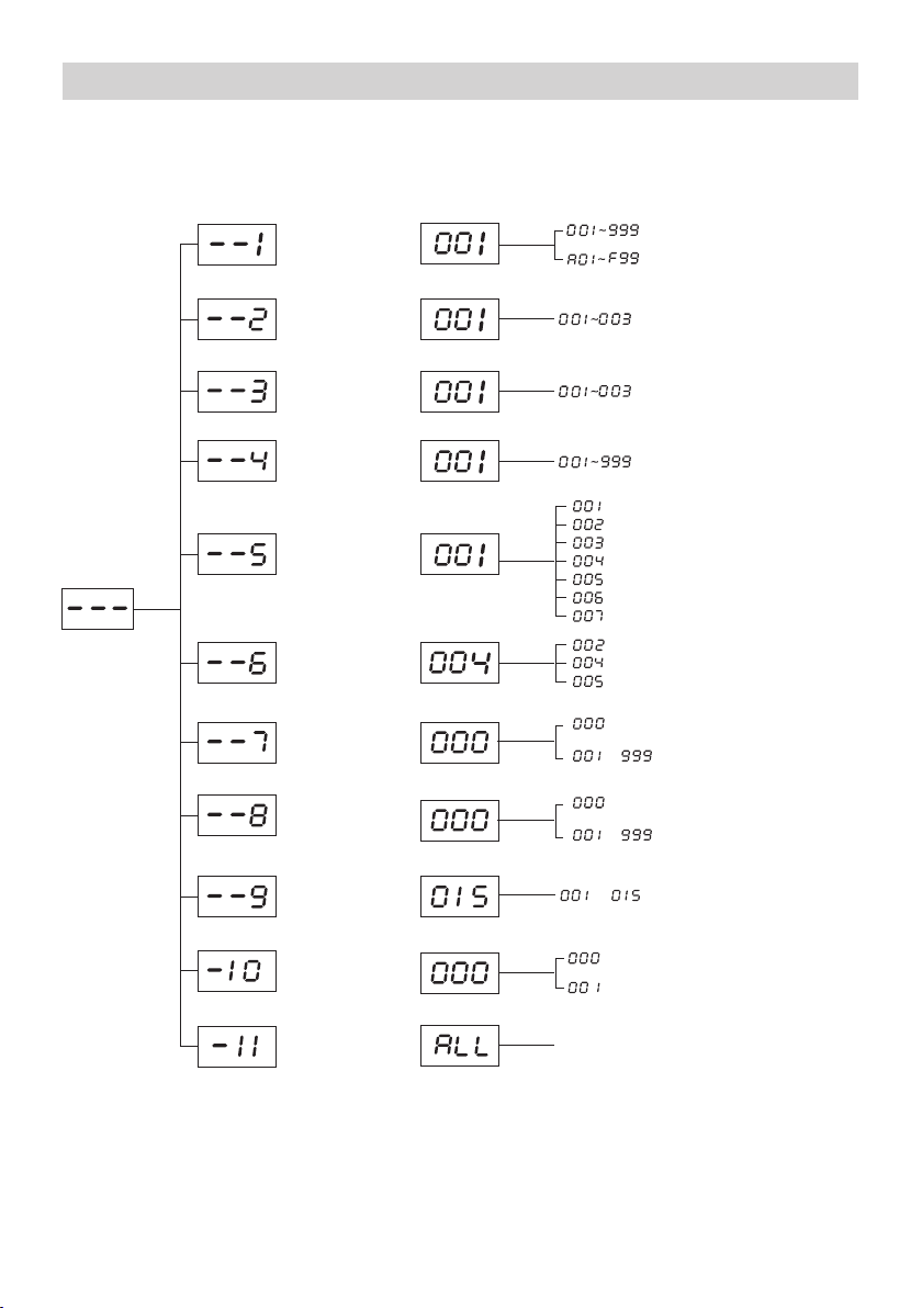
Press “SET” button to enter the first class settings menu. Then press “UP/DOWN” button to select
the menu from “--1" to “-11". And press “SET” button to enter submenu.
(1) --1: Pairing call buttons
Before do the pairing, please turn to "--6" to set key switch setting and "-10" to set the
working mode, like general mode or area mode.
Press [SET] button to enter "--1" submenu. The display will show "001", then press "UP/DOWN" to
select the number of calling transmitter.
A) General mode paring method
Press [UP/DOWN] button select one of the number, for example “001”, and then press any button
on the transmitter, the speaker will sound “successful registration” and the display screen turn to next
number “002” automatically. Then you can continue to do the next pairing up to number 999
transmitter (normal mode).
B) Area mode paring method
In area mode, the first digit of three is the area, it can show "A/b/C/d/E/F" areas, the last two digits
means the number from 01 to 99 in one area, press [UP/DOWN] button to select suitable area and
number.
C) Pair keypad call button
In key switch setting, select “005”, it is special for keypad mode.
Turn to “--1” pairing setting, the display shows “001”, then press any button on the keypad, the
receiver will get it and prompt “pairing successful, please continue.” and the display will turn to
"002". That means all the 999 codes are paired to the receiver.
Note: the receiver can pair 3 keypad in maximum.
(2) --2: Pair manager controller
Press [SET] button to enter "--2" submenu. The display will show "001", then press the button on
manager controller, the receiver will get it and prompt "pairing successful, please continue."
and the display will turn to "002". That means the pairing is finished.
When paird the manager controller, the button [SET/BACK/UP/DOWN] can replace the
receiver function button.
Note: the receiver can pair 3 manager controller in maximum. If you pair the fourth one, it
will cover the last one.
(3) --3: Delete manager controller
Press [SET] button to enter "--3" submenu. The display will show "001", press [UP/DOWN] button
to select which controller will be deleted, then press [DEL] button to delete. The receiver will prompt
"Dingdong" voice which means the deleting is finished.
(4) --4: Delete call buttons
Press [SET] button to enter "--4" submenu. The display will show "001", then press [UP/DOWN] to
select the number which will be deleted, then press [DEL] button to delete the call button, the receiver
will prompt "Dingdong" voice.
--4--
Operation

(5) --5: Prompt voice
Press [SET] button to enter "--5" submenu. The display will show "001", then press [UP/DOWN] to
select sound prompt mode.
001: No. xx call
002: Floor xx call
003: No. xx come in
004: No. xx treatment
005: No. xx take food
006: No. xx get food
007: Dingdong
(6) --6: key switch mode setting
Press [SET] button to enter "--6" submenu. The display will show "5", then press "UP/DOWN" to
just the key mode.
002: 2-key mode, which is suitable for 1/2-button calling transmitters.
004: 4-key mode, which is suitable for 1/3/4/5/6-button calling transmitters.
005: keypad mode
(7) --7: Display cycle time setting
Press [SET] button to enter "--7" submenu. The display will show "000", then press [UP/DOWN] to
adjust the display cycle time from “001" to “999" seconds. “000" means no cycle.
This function is that when there are several calling records, they will cycle display one by one
automatically.
(8)-8: Auto clear time setting
Press [SET] button to enter "--8" submenu. The display will show "040", then press [UP/DOWN] to
adjust the auto delete time from “001" to “999" seconds. “000" means no auto clear function.
This function is that when there is a calling record on the screen, after some time, the record will be
cleared automatically.
(9) --9: Volume
Press [SET] button to enter "--9" submenu. The display will show "15", then press [UP/DOWN] to
adjust the volume from “01" to “15" different level. “00" means mute.
(10) -10: Working mode setting
Press [SET] button to enter "-10" submenu. The display will show "000", then press [UP/DOWN]
to select the working mode.
000: General mode
001: Area mode
(11) -11: Restore the factory default setting
Press [SET] button to enter "Cd10" submenu. The display will show "no", then press [UP/DOWN] to
select restore function.
A) All the paired call buttons are deleted.
B) All the paired manager controller are deleted.
C) Prompt voice is “001" mode.
D) Key switch mode is “004” mode.
E) Cycle display time is “000”.
F) Auto clear time is “000”.
G) Volume is 5.
H) Working mode is general mode.
Select one option and press “SET” button, after 3s the host will restore to default settings and turn
back to standby status automatically.
--5--

--6--
Optional for transmitter
Notice
1. While it is working, please pull the antenna out for the best receiving effect.
2. In calling status, the [DEL] button is only clear the calling records, for delete the call buttons.
3. While it connects to the alarm, when there is alarm signal, it will sound 10s.
1-button mode: YK500-1E/F, YK1000-1C, YK200-1C, TSYK200-1, YK500-1H
2-button mode: YK1000-2C, TSYK500-2X, YK500-2H, TSYK1000-2X
3-button mode: YK500-3H
4-button mode: YK500-4X, YK500-4H, TSYK1000-4B, TSYK1000-4X,
TSYK2000-4X
6-button mode: TSYK500-6
Others mode: TSYK-JP999
FAQ
Problems Reasons Solutions
While power on, the receiver host
has no response.
The power adaptor is broken. Change the power adaptor.
The signal of some transmitters is
not enough.
The power of battery is low. Change the battery.
Receiver host cannot get some
transmitters of them.
These transmitters are deleted. Pair these transmitters again to
the receiver host.
No voice prompt while power on
or calling.
The volume is lowest. Adjust the volume louder.
Packing List
Name Quantity
Receiver host
Power adaptor
User manul
Warranty card
1 pc
1 pc
1 pc
1 pc

Table of contents
Other CallingSYS Receiver manuals