CalUltra UV-CalUltra 12 User manual

Operaon & Installaon Instrucons
CalUltra UV - Standard Systems
Model Rated Flow
UV-CalUltra 12
12 lpm
UV-CalUltra 22
22 lpm
UV-CalUltra 41
41 lpm
UV-CalUltra 79
79 lpm
Remember don’t guess....ASK

2|Page
Congratulaons on purchasing this ultraviolet disinfecon system. By purchasing a CalUltra
UV Disinfecon system you are receiving not only a high quality product but also peace of
mind. Protecng your water supply with a UV system gives you reassurance that your family
will have access to safe drinking water throughout your enre home with no chance of
microbiological contaminaon. This is a chemical free process which is simple in its concept
and eecve in its abilies to inacvate microorganisms present in the water supply. Simple
maintenance, connuous disinfecon and ulmately safe water, CalUltra makes it that easy.

3|Page
TABLE OF CONTENTS
Safety Consideraons ......................................................................................................... 4
Before You Begin ................................................................................................................ 4
Water Quality Parameters .................................................................................................. 4
Parts List ............................................................................................................................. 6
System Sizing ...................................................................................................................... 7
Locaon .............................................................................................................................. 7
Installaon ......................................................................................................................... 8
System Disinfecon .......................................................................................................... 11
Cleaning the Quartz Sleeve .............................................................................................. 11
Cleaning the UV Sensor .................................................................................................... 12
Operaon ......................................................................................................................... 12
CalUltra Controllers ................................................................................................ 13
Power-up Sequence ............................................................................................... 13
Operaonal Screens (un-monitored version) ........................................................ 14
Lamp Countdown Sequence .................................................................................. 15
Lamp Replacement ................................................................................................ 15
QR Codes ............................................................................................................... 16
System Troubleshoong......................................................................................... 17
Temperature Management Devices ................................................................................. 19
Expansion Modules .......................................................................................................... 19
CalUltra UV Standard Output System Specicaons ........................................................ 21
Limited Warranty Statement: ........................................................................................... 22
Warranty Registraon ...................................................................................................... 23

4|Page
Safety Consideraons
Although your UV system has been manufactured to the highest safety standards, care must be
followed when operang and/or maintaining your system.
1. Before servicing this equipment, disconnect the power cord from the electrical outlet.
2. Energy given o by the UV lamp is harmful to your eyes and skin. NEVER look directly
at an illuminated UV lamp without adequate eye protecon and always protect your skin
from direct exposure to the UV light.
3. For complete disinfecon, use ONLY Calmag genuine replacement parts.
4. Do not operate the unit if it has any damaged or missing components.
5. To avoid possible electrical shock, use only with a properly grounded electrical outlet.
6. Never perform any maintenance to the system unless you are comfortable in doing so.
Contact Calmag for service instrucons if required.
7. Do not use this system for any purpose other than what it was intended for. Misuse of this
system could potenally cause harm to the user or others.
8. Your system is intended to be installed indoors and away from leaking plumbing. DO NOT
plug the unit in if the system or any of the components are wet.
9. The disinfecon system should be directly installed into a ground fault circuit interrupter
(GFCI). If the use of an extension cord is required, the cord must be manufactured with a
minimum of 16 gauge wire and care should be taken to avoid potenal tripping hazards.
10. We recommend that a competant plumbing installer install the system.
Before You Begin
The following will be needed for installing the UV system:
Tools
• Pipe cuer, hacksaw or other specialized tools required to cut into your exisng
plumbing (e.g. if you have PEX piping)
• Soldering tools (torch, ux, emery cloth and solder)
• Correct sized spanners (for ghtening ngs)

5|Page
Other Materials
• Various pipe ngs
• PTFE tape
Water Quality parameters
UV disinfecon is extremely eecve against microorganisms but only if the UV light can pass
through the water it needs to treat. This means that the quality of your water is very important
in order to ensure complete disinfecon.
Treated water should be tested for at the least the parameters listed below. If the water exceeds
the listed parameters Calmag strongly recommends that appropriate pretreatment equipment
be installed (equipment required will depend on parameters being treated):
Hardness: <120 ppm – if hardness level is 120 ppm or slightly below the quartz
sleeve must be cleaned periodically in order to ensure ecient UV
penetraon; if above the water must be soened.
Iron (Fe): <0.3 ppm
Manganese (Mn): <0.05 ppm
Turbidity: < 1 NTU
Tannins (organics): <0.1 ppm
UVT (transmiance): >85% (Please contact Calmag if water has a UVT that is less than
80% for pre-treatment recommendaons)
You can have your water tested at a private analycal laboratory or by your local council. It
is always recommended to install pre-ltraon of at least 5 microns prior to a CalUltra UV
disinfecon system. The CalUltra 12 and CalUltra 22 models are already provided with a pre-
lter. For other models, please contact Calmag for the appropriate lter housing and cartridge.

6|Page
Parts List
Unpack the system and ensure all the components are included with the system. Your system is
shipped with the following components that are pre-assembled:
CalUltra domesc units
CONTROLLER
GLOW PLUG
RC-B56.03-CM
300016 Complete Assembly
310026 Teon Plug
310040 O-Ring
390007 Brass Nut
GLAND NUT
O-RING
SLEEVE SPRING
QUARTZ SLEEVE
CHAMBER
UV LAMP
320006
310038
310039
LAMP KEY
Either
UV-SLEEVE-QS12 12 lpm
series or
UV-SLEEVE-QS22 22 lpm
series or
UV-SLEEVE-QS41 41 lpm
series or
UV-SLEEVE-QS79 79 lpm
series
Either
UV-BULB-B12 12 lpm
series or
UV-BULB-B22 22 lpm
series or
UV-BULB-B41 41 lpm
series or
UV-BULB-B79 79 lpm
series

7|Page
System Sizing
All CalUltra UV systems are rated for a specic ow rate in water that meets the quality parameters
on page 5. PLEASE NOTE that increasing the ow above this rang or disinfecng water that
does not meet the quality parameters will decrease the dose and therefore compromise the
microorganism inacvaon.
It is important to know the maximum ow rate that your water system delivers. If you do not
have this informaon, you can simply ll a 10 litre bucket with water from the mains supply and
tome how long it takes to ll up. This can then be calculated to litres per minute and the the
approriate Calmag UV unit should be chosen.
Locaon
Choose a locaon where the main cold water line is accessible. The system must be installed
aer other water treatment equipment (soener or lters), but before any branches (See Figure
1). Calmag recommends that a 5 micron lter be installed before the UV system for a nal
polishing step before the water is disinfected (included with the CalUltra 12 and CalUltra 22
models).
Figure 1. Example Installaon

8|Page
To facilitate lamp removal, ensure there is enough space at the lamp connector end to safely
remove the UV lamp and/or quartz sleeve (See Figure 2). The controller will require a ground
fault circuit interrupter (GFCI or GFI) outlet and should be mounted beside or above the
chamber. PLEASE NOTE: All CalUltra UV disinfecon systems are intended for indoor use only as
they should not be exposed to the elements.
Installaon
Step 1: The reactor can be installed either horizontally or ver-
cally using the clamps provided. Vercal installaon allows any air
that may be in the lines to be easily purged from the system.
Step 2: The use of a by-pass assembly is recommended as it will
allow you to isolate the UV unit. This will allow for easier access in
case maintenance is required (See Figure 3).
Step 3: Use appropriate xings to mount the UV unit.
Step 4: For water supplies where the maximum ow rate is un-
known, a ow restrictor is recommended so that the rated ow of
your parcular CalUltra system is not exceeded. The ow restrictor
should be installed on the outlet port of the unit.
Step 5: It is recommended to have a competent plumber connect
the UV unit to the water supply.
Figure 3. By-pass assembly
Figure 2. Lamp Removal
Spacing
leave at least
an additonal
reactor length
to facilitate
lamp and
sleeve removal
Note: Installaon of your
CalUltra disinfecon systems
should comply with applicable
regulaons. Please check if
unsure.

9|Page
ON PRE-BUILT UNITS STEPS 6 & 7 HAVE BEEN PRE-ASSEMBLED
Step 6: Once the system has been plumbed in, gently remove the
quartz sleeve from its packaging being careful not to touch the length
with your hands. The use of coon gloves is recommended for this
procedure as oils from the hands can leave residue on the sleeve
and lamp which can ulmately block the UV light from geng to the
water.
Carefully slide the sleeve into the reactor unl you can feel it hit the
opposite end of the reactor. Align the sleeve so it centered along the
length of the reactor, then gently push it in to lock it into the internal
centering springs in the far side of the reactor. CAUTION: Pushing
too hard when the sleeve is not aligned can damage the centering
springs. Slide the o-ring onto the sleeve unl it is bued up against
the reactor.
Figure 4. Quartz
Sleeve Installaon
Step 7: Hand ghten the provided gland nut over the quartz sleeve onto the threaded end of
the reactor. It has a posive stop to prevent over-ghtening. A rm force may be required to fully
ghten the gland nut, but DO NOT USE TOOLS for this step. Insert the provided stainless steel
compression spring into the quartz sleeve. The spring works with the lamp and lamp connector
to create the proper lamp alignment. PLEASE NOTE: DO NOT install a UV lamp inside the quartz
sleeve without the sleeve spring in place.
EXTRAS
Step 8: Install the UV sensor (oponal extra). Align the at poron so it faces the gland nut
end and matches up with the half metal lip on the sensor port (see Figure 5). Insert the sensor
so it is fully seated and hand ghten the sensor nut. If no sensor is being installed insert the glow
nut into the port.
Figure 5. UV Sensor Installaon Figure 6. IEP Connecon

10|Page
Step 9: The unit is now ready for water ow. When all plumbing connecons have been
completed, slowly turn on the water supply and check for leaks. Make sure the by-pass valves
are funconing properly and that the water is owing through the unit. The most common leak
is from the o-ring not making a proper seal on the unit. For new installaons, review steps 6 and
7. For older systems drain the unit, remove the o-ring, dry it and reapply silicon grease. Reinstall
the o-ring ensuring that it is properly sealed against the unit and check again for leaks.
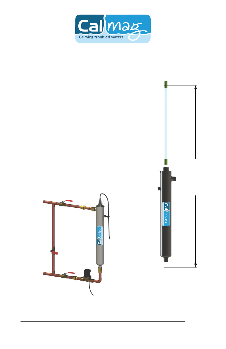
Step 10: Mount the controller (if required) to the wall so it is above or beside the reactor to
ensure that no moisture can deposit on any of the connecons (see Figure 1). Always mount the
controller vercally. For sensor systems, insert the sensor connector into the IEP port located on
the right side of the controller (Figure 6). For the sensor to be recognized by the controller, the
controller power must be plugged in last. Do not plug the controller power cord in before the
last step.
ON PRE-BUILT UNITS STEPS 11 - 14 HAVE BEEN PRE-ASSEMBLED
Step 11: Always hold UV lamps by their ceramic ends, not by the lamp quartz. Remove the lamp
from its packaging. Again, the use of coon gloves is recommended. Remove the lamp key from
the lamp’s connector and set it aside for the next step. Be careful to not touch the key’s exposed
contacts. Insert the UV lamp into the reactor, being careful not to drop it.
Figure 7a. Standard Output UV
Lamp Connecon
Step 12: Install the lamp key into the controller. The key always comes packaged with the lamp
and sits on the connector. With the key removed from the lamp, orient it so the label is upright
and facing you. The key will plug into the lamp key port on the right side of the controller (Figure
8).
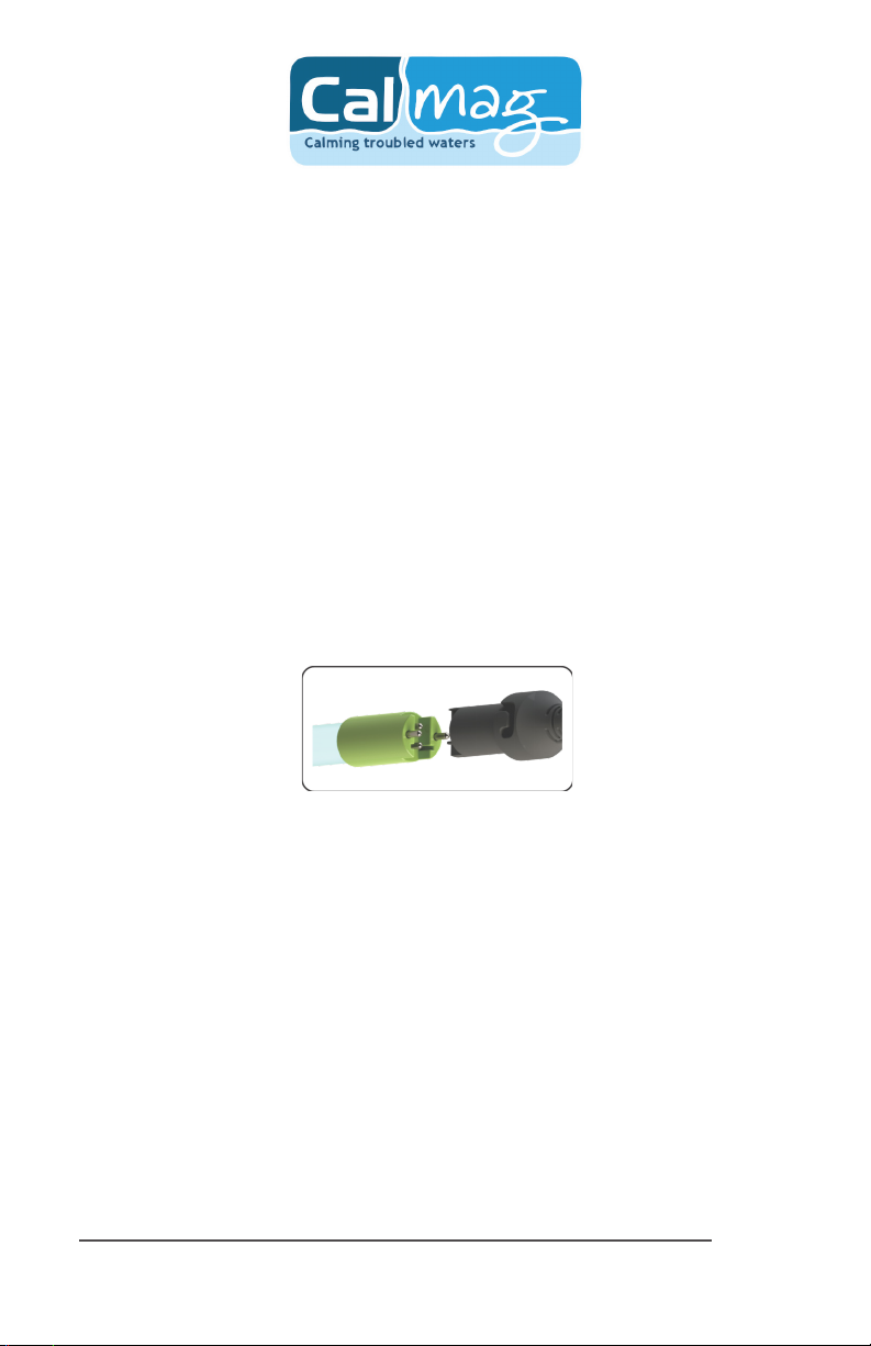
Step 13: Plug the lamp connector into the lamp. Note the keying for proper alignment (see
Figure 7). Insert the lamp connector into the gland nut and turn the connector approximately ¼
turn to lock the connector to the gland nut as in Figure 9.

11|Page
Figure 8. Lamp Key Installaon
Figure 9. Lamp Connector
Step 14: Tighten the capve ground screw to the ground lug on the UV reactor to ensure proper
grounding.
Figure 10. Ground Screw Connecon
Step 15: Your system is now ready to be plugged into the appropriate GFCI protected outlet.
Refer to the following secon before any water is allowed to ow through the system.
System Disinfecon
With a new installaon, or any me the UV system is shut down for service, without power, or is
inoperave for any other reason, the lines in the home or facility could be contaminated. Use the
following steps to fully disinfect the lines throughout the enre home or facility.
Step 1: Check for and remove any “dead legs” in the lines throughout the home as these can
harbor bacteria. Plug in the UV system and wait unl it is ready for operaon.
Step 2: Remove the lter cartridge from the lter housing and ll it with 1-2 cups of household
bleach (most are 5.25% chlorine). Replace the lter housing and slowly turn on the water supply.
Step 3: At a water outlet, run the water unl bleach can be smelled. Repeat this for all taps,
toilets, shower heads, refrigerators, outdoor taps, washing machine, dishwasher, etc. at the
home or facility. Once nished, wait a minumum of 30 minutes before connuing.

12|Page
Step 4: Reinstall the lter cartridge into the lter housing and ush the chlorine soluon by
opening all taps unl chlorine can no longer be detected. Your home has now been completely
disinfected with your CalUltra UV system ready to inacvate any microorganisms that enter the
home.
Cleaning the Quartz Sleeve
Depending on the water quality, the quartz sleeve may require periodic cleaning. At a minimum,
the quartz sleeve should be cleaned on an annual basis. The following steps outline a basic
cleaning procedure.
Step 1: If a by-pass assembly is installed, shut the inlet valve o to prevent water ow through
the system. Otherwise, turn o main water inlet valve (and/or turn o the water pump).
Step 2: Disconnect power cord of UV system from electrical outlet.
Step 3: Release water pressure by opening a downstream tap and then close the outlet shut-
o valve (if any). If there is no outlet shut-o valve, expect water to drain from the system as the
head pressure in the system will cause the water to ow back down.
Step 4: Remove the capve ground screw from the ground lug on the UV unit.
Step 5: Remove the lamp connector from the unit (gland nut) by pushing the lamp connector
in and turning it ¼ turn counter-clockwise. Disconnect the lamp connector from the lamp.
CAUTION: the lamp may be hot!
Step 6: Being careful to touch only the ceramic ends, remove the lamp out of the unit.
Step 7: Unscrew the gland nut from the unit exposing the end of the quartz sleeve.
Step 8: Remove the quartz sleeve and o-ring by gently twisng and pulling the quartz sleeve.
Step 9: Using a so, lint-free cloth or towel wipe the sleeve down using a commercial scale
cleaner. This removes scaling or iron deposits that may be on the outside of the quartz sleeve.
Be careful not to get any moisture or liquids inside of the sleeve.
Step 10: Dry the sleeve with separate cloth.
Step 11: Replace the o-ring and slide the sleeve back into the reactor following steps 7 and 8
from the installaon secon of the manual.
Cleaning the UV Sensor (if applicable)
Depending on the water quality, the UV sensor may require periodic cleaning. At a minimum,
the UV sensor should be cleaning on an annual basis. The following steps outline a basic clean-
ing procedure.

13|Page
Step 1: If a by-pass assembly is installed, shut the inlet valve o to prevent water ow through
the system. Otherwise, turn o main water inlet valve (and/or turn o the water pump).
Step 2: Disconnect power cord of UV system from electrical outlet.
Step 3: Release water pressure by opening a downstream tap and then close the outlet shut-
o valve (if any). If there is no outlet shut-o valve, expect water to drain from the system as the
head pressure in the system will cause the water to ow back down.
Step 4: Place something under the unit to catch any water that may come out of the unit
during the removal of the UV sensor.
Step 5: Unscrew (counterclockwise) sensor nut from the unit and pull the sensor slowly out of
the sensor port.
Step 6: Holding the sensor in your hand wipe the at poron (sensor face) of the sensor with
isopropyl alcohol using a clean lint-free cloth.
Step 7: Replace sensor following step 9 from the installaon secon of the manual.
Operaon
CalUltra systems come with a feature laden controller that incorporates both the lamp driver
(ballast) and control features in one water-ght case. Four main controllers are available for the
CalUltra systems (depending on your model). All four models feature a power factor corrected,
constant current lamp driver with a universal power input.
Please Note: While the display screen is red and the buzzer is sounding the water from the system
should NOT be consumed. If any water does pass through the system during this period, please
follow the disinfecon procedure as outlined in this manual before the water is consumed. Even
though they have a visual and audible warning built into the controller, a “normal” status screen
does not necessarily indicate that the water coming from this system is in fact potable (safe to
drink). These systems do not measure the level of disinfecon; they simply measure the “on-
o” status of the lamp. Please have your water checked for microbiological contaminants on a
regular basis.

14|Page
CalUltra Controllers
A full colour LCD screen provides the user with a detailed descripon of the
system’s performance in addion to providing any applicable fault messages
and system diagnoscs. The controllers used in both the un-monitored and
monitored systems are idencal. The dierence is that the monitored series
of products include a UV intensity monitor. All CalUltra controllers include
an “innite expandability port” located on the right side of the controller.
Simply plug in an oponal UV sensor module into the expandability port of a
CalUltra controller and the system will now monitor the UV intensity of the
system!
Power-up Sequence
On start up, the controller will run through a diagnosc start-up and the sequence will be
displayed as follows on the colour LCD:
Next, the controller checks for and inializes any oponal modules that may be aached to the
system.
UV Sensor
Module Check
OR
Solenoid
Module Check
OR
4-20 mA
Module Check
OR

15|Page
Ethernet
Module Check
OR
Remote Alarm
Module Check
OR
A nal module screen is displayed showing which specic modules were inialized.
The controller then displays the lamp opmizaon screen for 60 seconds to allow the lamp to
reach its opmum output. Finally, a nal “start-up complete” screen is displayed. The system will
now be ready to disinfect water ow.
all detected modules lamp reaching max output successful start-up
Operaonal Screens (standard product)
On systems without the UV monitor, the default screen shows the CalUltra Home Screen. At
any point during operaon the user is able to scroll through the CalUltra Home Screen, Lamp
life remaining, QR Code, Contact Info and Maintenance Parts screens by pressing the buon
located on the front of the controller.
Operaonal Screens (with UV monitor)
On systems with the UV monitor, the system will display the same screens as on the un-monitored
version except the UV Intensity replaces the home screen. The UV Intensity screen displays the
level of UV light detected by the sensor. UV intensity can be aected by poor water quality,
scaling on the quartz sleeve and/or sensor, lamp failure or lamp expiring. The following screens
show the UV Intensity dropping.

16|Page
Below 56%, the numbers and warning sign turn red and an audible chirp is given by the ballast
every 15 seconds. Below 51%, the screen is solid red and a constant audible alarm is given. This
alternates with a screen indicang “water may be unsafe for consumpon”. With the solenoid
module, the controller de-acvates the solenoid valve, shung o all water ow.
audible chirp every
15 seconds
audible chirp every
15 seconds
constant audible
alarm
cycles with red low
uv screen
Lamp Countdown Sequence
The system counts down the number of days unl a lamp change is required.
At thirty days remaining, the LED or display screen will change to a yellow cauon indicator.
At seven days remaining, the sytem will addionaly repeat an audible chirp. Past the zero day
threshold, the LED or display screen changes to solid red with a connuous buzzer.
At any point during this sequence, the audible chirp or alarm can be deferred for seven days
by holding the controller buon down for a period of ve seconds. The number of deferrals
used will be displayed as below. Once the deferral expires, the alarm will sound once again. The

17|Page
deferral can be repeated up to three mes. PLEASE NOTE: At any point aer lamp expiraon,
the water may be unsafe for consumpon and should not be consumed without another form
of disinfecon.
Lamp Replacement
Aer the lamp is expired, it must be replaced with the same part number as indicated on the
Maintenance Parts screen or on the label on the unit. With the system powered down, remove
and discard the lamp key from the controller. The replacement lamp is packaged with a lamp
key on the connector at the end of the lamp. Remove the key from the lamp and place it in the
controller. Refer to Installaon, starng with step 11 (page 10) for instrucons on installing the
new lamp.
QR Codes
A QR code (Quick Response code) is a matrix barcode rst designed for the
automove industry. Calmag uses the QR code to store a link to a specic
page on our website. Users with a camera phone equipped with the correct
reader applicaon can scan the image of the QR code and over a wireless
network connect to a Calmag web page in the phone’s browser. Calmag’s QR
webpage has informaon on how to purchase replacement components as
well as a helpful video directory on system servicing (i.e. How to change a UV
lamp or quartz sleeve). To access the QR code on the Calmag controller, press
the control buon unl the QR code screen appears.

18|Page
System Troubleshoong
Hard Alarms: The following give a constant audible alarm. If present, the solenoid valve is closed,
and the 4-20, remote alarm and ethernet modules transmit the alarm.
System Display Problem Resoluon
The system has detected
a problem with the
lamp.
Reset lamp protecon circuit
-unplug unit for 10 seconds.
Replace the lamp with the
part as indicated on the
silver label on the unit or
on the Maintenance parts
screen.
Although the lamp is
powered and visibly
illuminated, due to the
lamp’s age its UV output
is no longer sucient for
proper disinfecon.
Replace the lamp with the
part as indicated on the
silver label on the unit or
on the Maintenance parts
screen.
Low UV Intensity.
Remove and clean the
quartz sleeve and sensor.
Check water quality meets
requirements on page 5 and
add ltraon as required.
Replace lamp.
Wrong lamp or sensor
installed.
Replace component with
proper model as indicated.
The UV sensor is no
longer communicang
with the system.
Ensure all modules are
connected properly to the
system and to each other.
Modules can be tested
individually by plugging in
one at a me and cycling
power to the system.
Replace any module that is
not detected when plugged
directly into the controller.
A bad connecon has
been detected in the IEP
port.

19|Page
Missing or incorrect
lamp key.
Ensure the lamp key
(packed with the lamp, on
the connector) is installed.
Unplug and reinstall the
key. Ensure the key part
number matches Lamp on
Maintenance Parts screen.
So Alarms: The following remaining errors give a 15 second audible chirp only
System Display Problem Resoluon
The module indicated is
no longer communicat-
ing to with the system.
Ensure all modules are
connected properly to the
system and to each other.
Modules can be tested
individually by plugging in
one at a me and cycling
power to the system.
Replace any module that is
not detected when plugged
directly into the controller.
Warning: Aer any hard alarm, the home or facility should be disinfected. Follow the steps
under the “System Disinfecon” heading.
Boil Water Advisory: If any failure occurs on a CalUltra UV system, the water
must not be used for human consumpon unl the system is returned to a
safe operaonal mode. If the water is used for human consumpon during this
period, the water must be boiled (minimum 20 minutes at a full boil) prior to
consumpon.

20|Page
OPTIONAL EXTRAS
Temperature Management Devices
Your CalUltra UV system is designed to run connuously to ensure opmal disinfecon. However,
during periods when no water is drawn through the system, the energy from the disinfecon
process can cause the temperature of the water inside the chamber to rise. In extreme situaons
elevated water temperature or the uctuaon in temperature can lower the output of the UV
lamp. In these cases, or if the elevated water temperature is a nuisance, Calmag recommends
one of the following forms of temperature management devices.
Cooling Fan
Designed for use on the 20 gpm system, the fan runs connuously to cool the
water by forced convecon. The long-life fan is powered independently using a
compact modular power adapter that operates from 90-265V (47-63Hz). Contact
Calmag for details.
Temperature Relief Valve (TRV)
On reaching a higher temperature, the TRV is designed to drain a small amount
of water to allow fresh, cooler water to enter the system. The TRV works without
power and comes complete with 10’ of drain line. Contact Calmag for details.
Expansion Modules
CalUltra controllers incorporate an “Innite Expandability Port” (IEP) which allows for expansion
to the UV sensor and all other modules. Each module (including the sensor) comes with both a
male and female connecon. Connect any device to the controller and all subsequent devices
are then connected into the female end of last device added in a “daisy chain” conguraon.
The following oponal expansion modules are available for use on all CalUltra controllers.
Contact Calmag for further informaon.
This manual suits for next models
3
Table of contents
Popular Water Filtration System manuals by other brands

deconta
deconta green dec G 50 Original instruction manual

Watts
Watts Hydro-Safe QTBRWMAX-1S-1M Installation, operation and maintenance manual

QED
QED MicroPurge MP25 quick start guide

Samlex Europe
Samlex Europe BSWM 160 DUAL owner's manual

Evoqua
Evoqua Neptune Benson Defender FP Series Installation and operation manual

CAB
CAB MAESTRO 2M Operator's manual