4Quick Start Installation Guide
807119US v1.04 11.22 G5 BCS Quick Start Guide
Quick Start Installation Guide
807119US v1.04 11.22 G5 BCS Quick Start Guide
5
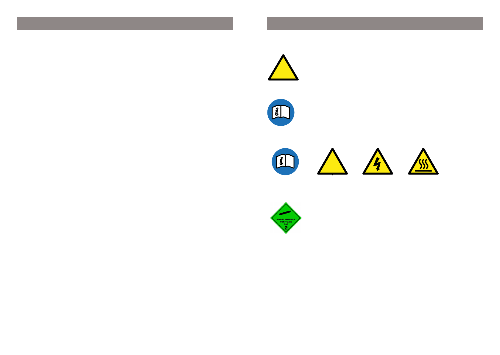
SECTION 2: IMPORTANT SAFETY INSTRUCTIONS
Safety
This appliance is not intended for use by children under 8 years or persons
(including children under 8 years) with reduced physical, sensory or mental
capabilities, or lack of experience and knowledge, unless they have been
given supervision or instruction concerning the use of the appliance by a
person responsible for their safety. Children should be supervised to ensure
that they do not play with the appliance.
Ventilation
Keep ventilation openings, in the appliance enclosure or in the built-in
structure, clear of obstruction.
Do not use mechanical devices or other means to accelerate the defrosting
process, other than those recommended by the manufacturer.
Do not store explosive substances such as aerosol cans with a flammable
propellant in this appliance.
CO2
• Keep out of reach of children.
• Use according to MSDS (material safety data sheet).
• Pressurized container. Contains gas under pressure,may
explode if heated.
• Protect from sunlight.
• Do not expose to temperatures exceeding 122ºF, (50ºC).
• Do not expose to naked flame or any incandescent material.
• Do not pierce or burn, even after use. Avoid shock.
• High concentration of gas may cause asphyxiation.
Compliance
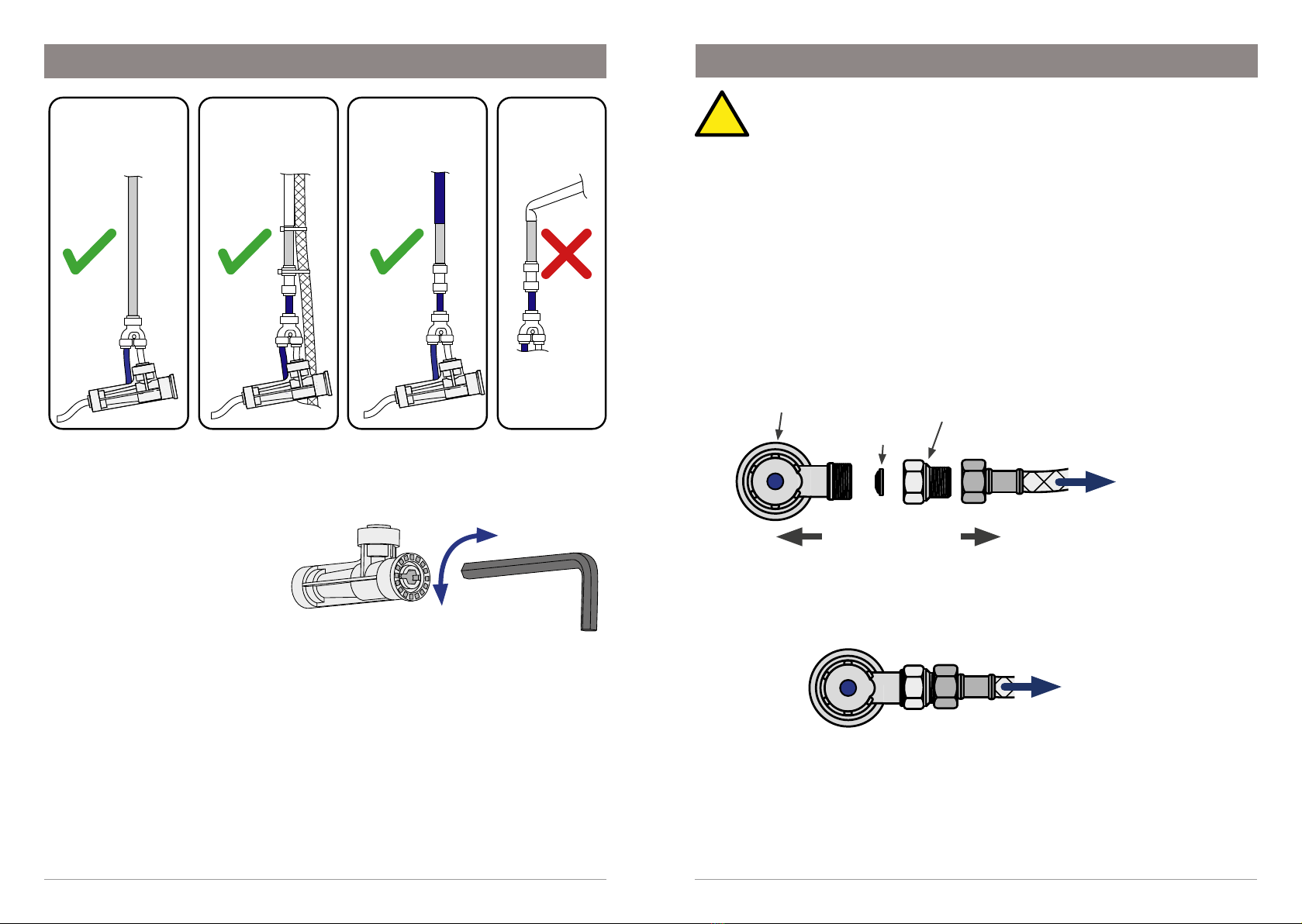
All Plumbing and Electrical connections must comply with local,
state and federal codes.
All Plumbing and Electrical connections must be made in accordance with local
regulations.
Ensure the electrical power supply at the installation site is suitable for your
HydroTap.
HydroTap models are rated for the following installations:
• Commercial - 220-240VAC 50/60Hz or 230VAC 60Hz
• Residential (120V) - 110-120VAC 50/60Hz
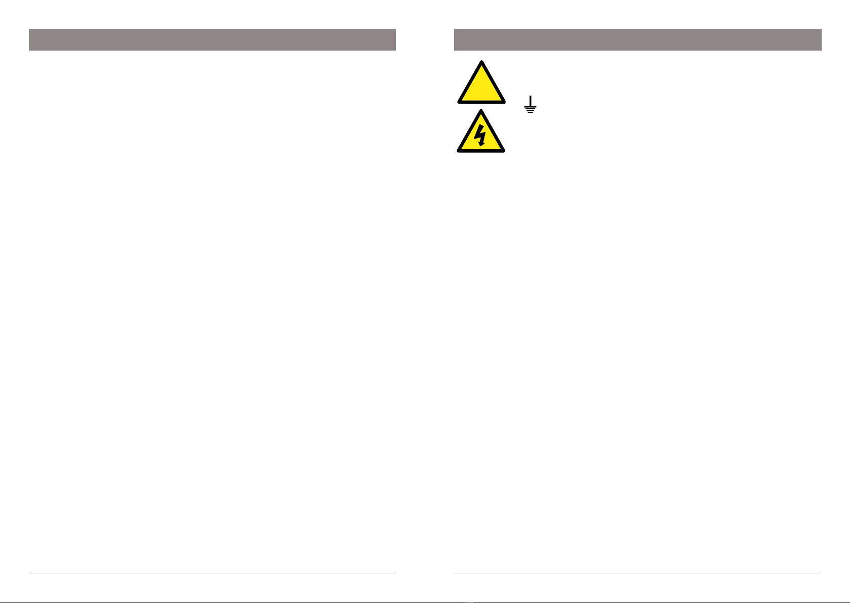
SECTION 2: IMPORTANT SAFETY INSTRUCTIONS
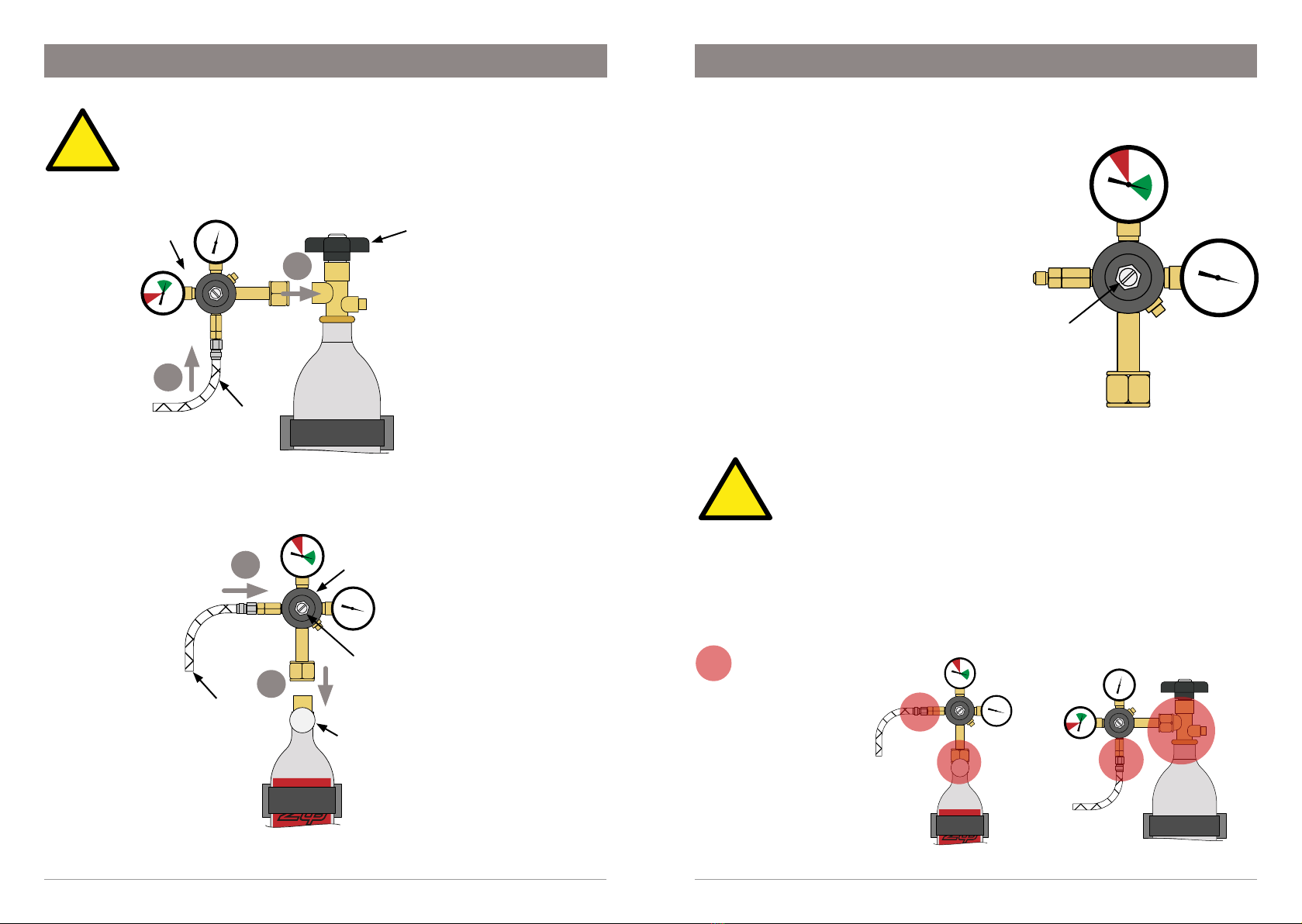
• Use only in an upright position.
• The cylinder must be used with the supplied pressure regulator.
• Store in a location with a volume no less than 65 cubic yards (50 cubic
meters) for each 5 lb, (2.27kg) cylinder.
• If more than 1 gas cylinder containing COis present within the same
location, the recommended ventilated area should be in proportion to
the number of gas cylinders stored in that location. A ventilated area is a
non-enclosed area which could include the kitchen, living room etc.
• Refer to the gas cylinder and MSDS for a complete list of warnings
(www.na.zipwater.com).
Qualifications
To avoid hazards, all installation procedures must be carried out by a
suitably qualified tradesperson. The power cable and power outlet must be
in a safe visible position for connection.
Venting
Sometimes steam and / or boiling water droplets may discharge through a
vent outlet on the tap. If not using the font, ensure the tap body is located
so the tap outlet safely dispenses into the sink bowl.
Lifting
Take care when lifting. The Command Center may exceed safe lifting
limits. If you feel this is beyond your personal capabilities, please seek
assistance with the lift. The weight of the Command Center is marked on
the packaging. Do not lift the Command Center by the front cover or any of
its connections.
Airflow
The ambient operating temperatures, when installed in a cabinet, must
be between 41 - 95ºF, (5 - 35ºC) . The system will operate satisfactorily
only with proper air ventilation. Air gaps of 2”,(50mm) on each side, and
8”,(200mm) above must be provided. See section 6 for correct ventilation
details.
Altitude
Water boils at varying temperatures at different altitudes. The HydroTap
adjusts for this during startup calibration and will recalibrate itself on a
regular basis.