cam SX50 User manual

SPIRAL KNEADING MACHINE
Models: SX50-SX60-TSX50-TSX60
TSVX50-TSVX60
INSTALLATION OPERATING AND MAINTENANCE
ISTRUCTIONS

2- Ed.1/2012 Rev.0
ENG
INTRODUCTION
READ THIS ENTIRE MANUAL BEFORE UNPACKING AND INSTALLING THIS
PRODUCT.
Dear client,
Thank you for choosing a quality product manufactured by us.
Our expert production follows the guiding principle of the strictest quality control of each
component so as to guarantee that our products will function efficiently far into the future.
The mechanical, electrical, and electronic parts were designed and manufactured to
guarantee reliability and high-quality functioning.
The use of parts that are not original could cause functioning problems or damage to the
product. Therefore, always ask for any spare parts from authorized dealers to return the
product to perfect working order and to guarantee that it will last longer.
All the machines we manufacture are made using modern technology and systems of
tested reliability. We systematically referred to the current standards and regulations for
mechanical products, specifically the UNI standards and the CEI standards for electric and
electronic equipment. The units that are described in this manual, like all our products,
are manufactured according to criteria of good practice and in strict compliance with the
European directives and related regulations.
Note:
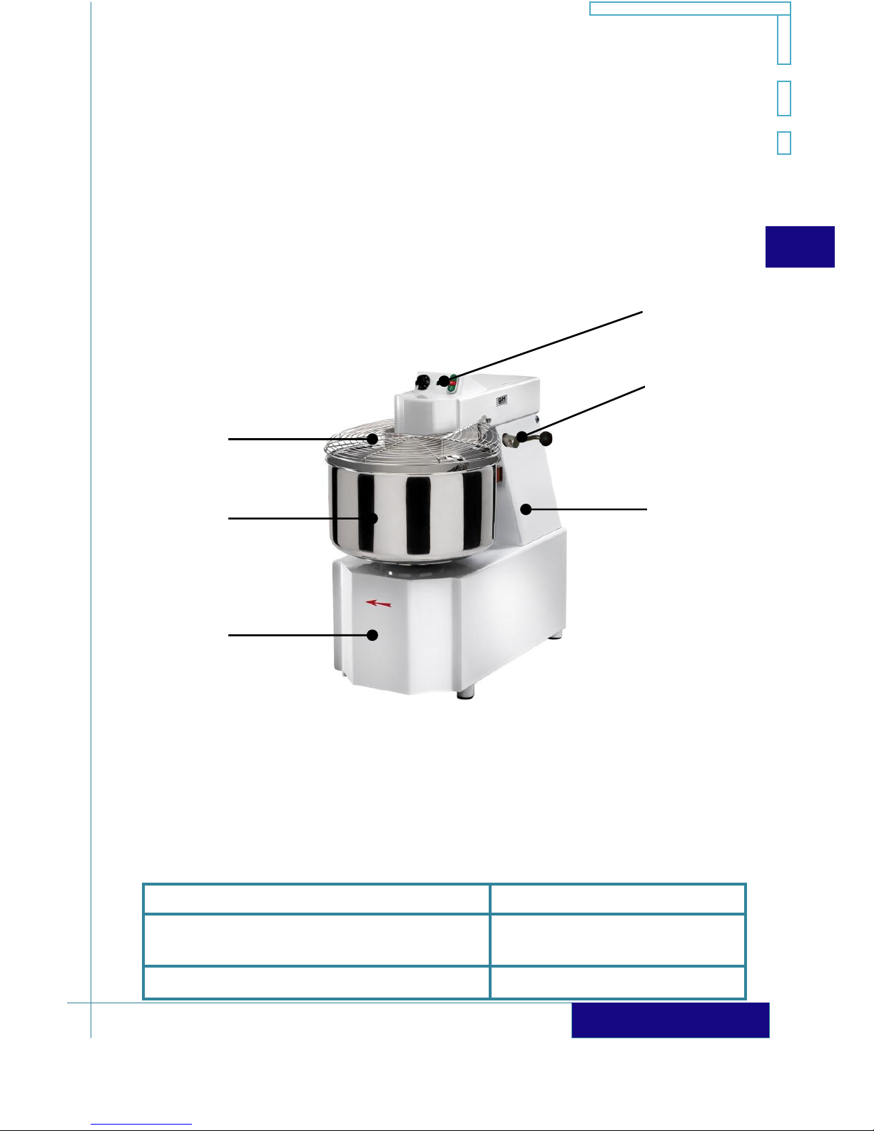
The unit that is illustrated or described could be different from your unit for
commercial or technical reasons, depending on the standards and safety
regulations in force in the different countries in Europe and in the world. The
technical specifications and dimensions, the described functioning, and any
equipment cited are not binding. The figures show a generic unit only for
illustrative purposes.
Before operating on the machine, read carefully the
technical instructions included in this manual and follow the
indications described.
Keep this manual and all the annexed literature in a readily
accessible place and known to all the users (operators and
maintenance personnel).

SPIRAL KNEADING MACHINE - SX / TXS / TSVX
Ed.1/2012 Rev.0 - 3
ENG
GENERAL TABLE OF CONTENTS
Section 1: General information - Instructions
1.1 - Introduction and safety recommendations
1.1.1 - Residual risks
1.2 - Machine data and use
1.2.1 - Application sectors
1.3 - EC Declaration of Conformity
1.4 - Technical specifications
1.4.1 - Sound level
1.4.2 - Productivity
1.5 - Machine description
1.6 - Packing and standard equipment
1.7 - Safety devices
1.7.1 - Safety devices of electric equipment - Wiring diagram
1.7.2 - Safety devices of mechanical equipment
1.7.3 - Operator safety
Section 2: Installing the machine
2.1 - Unpacking
2.2 - Position in place
2.3 - Connection to the electrical power supply
2.4 - Preliminary installation requirements
2.4.1 - Technical information reserved to the qualified installer
Section 3: Intended use of machine
3.1 - Controls descriptions
3.2 - Machine start-up
3.3 - Cleaning the machine
3.4 - Regular maintenance
3.5 - Troubleshooting
3.6 - Long inactivity periods
3.7 - Disposal
Section 4: Spare parts - Electric Diagram
4.1 - List of spare parts
4.2 - Connecting diagram
Appendix
Warranty terms

4- Ed.1/2012 Rev.0
ENG
SECTION 1
GENERAL INFORMATION - INSTRUCTIONS
1.1 Introduction and safety recommendations
These operating and maintenance instructions are intended to operators and qualified
personnel for the correct use of the machine.
In order to facilitate understanding of the content of this manual, we provide a list of
terms and symbols used:
Definition - Symbol
Description
Danger Zone
Any area within and/or around the machine in which an
exposed person is subject to a risk to his health or safety.
Exposed Person
Any person who is wholly or partially in a danger zone.
Operator
Person in charge of installing, operating, adjusting, servicing
and cleaning the machine.
Provides significant information.
Indicates a potentially hazardous situation that may arise if
the operations described are not carried out correctly, and
which may result in damage to the machine and/or serious
injury to operators.
Warnings of precautions and safety are written in this manual in order to remind the
operator and staff on the possible dangers due to improper use of this machine.
The instructions or the warnings do not want to substitute the safe working practice but
to complete them and to stimulate their compliance.
Only warning does not eliminate the hazard.
Failure to observe this safety recommendations and improper use of
the device may pose risk of accidents for the operator or other
people.

SPIRAL KNEADING MACHINE - SX / TXS / TSVX
Ed.1/2012 Rev.0 - 5
ENG
1.1.1 Residual risks
In compliance with section 1.7.3 “Warning of residual risks” of the Machine Directive
89/392 and subsequent amendments, if the protections applied, also in compliance with
the aforementioned Directive, do not observe the following recommendations
regarding:
clothing that must be used (with no loose parts and/or accessories hanging
down from the body);
connection to the mains (respect the cyclic frequency of the phases to avoid
that the spiral and the bowl turn in opposite directions);
the risk of crushing and/or shearing of pieces will not be completely eliminated.
1.2 Machine data and use
The manual describes the operating instructions for the spiral kneaders with fixed or
removable bowl.
Models: SX-50; SX-60; TSX-50; TSX-60;
TSVX-50; TSVX-60.
This type of electrical machine transforms, with the addition of water and,
sometimes, vegetable or animal fats and oils or any other ingredient, a mix
of flour, into a doughy and homogeneous mass used to make pizza, bread,
pastry or sweets.
The model identification plate, placed at the rear part of the machine, next to the power
line is as follows:

6- Ed.1/2012 Rev.0
ENG
1.2.1 Application sectors
All the models are suitable to be used in the field of handmade or professional products,
therefore, they can be used in:
Kitchens of restaurants, communities, canteens, pizza houses, etc.
In bakeries or pasta factories.
Wherever it is necessary to prepare flour dough.
1.3 EC Declaration of Conformity

SPIRAL KNEADING MACHINE - SX / TXS / TSVX
Ed.1/2012 Rev.0 - 7
ENG
1.4 Technical specifications
Model
External
measuremen
ts (mm)
Bowl
capacity
(mm)
Packages
dimensions
(mm)
Weight
(Kg)
Gears
motors in
oil bath
SX 50
L x P x H
530x940x930
53 lt 45 kg
Ø500x300
L x P x H
690x1040x1100
207
X
SX 60
L x P x H
640x990x930
76 lt 64 kg
Ø600x300
L x P x H
690x1040x1100
213
X
TSX 50
L x P x H
530x940x930
53 lt 45 kg
Ø500x300
L x P x H
690x1040x1100
217
X
TSX 60
L x P x H
640x990x930
76 lt 64 kg
Ø600x300
L x P x H
690x1040x1100
223
X
TSVX 50
L x P x H
530x940x930
53 lt 45 kg
Ø500x300
L x P x H
690x1040x1100
218
X
TSVX 60
L x P x H
640x990x930
76 lt 64 kg
Ø600x300
L x P x H
690x1040x1100
224
X
Model
Single-phase
installed power
230V 50Hz
Three-phase
installed power
400V 50Hz
2 Speed Three-phase
installed power
TR 400V 50Hz
SX 50
//
2,5 kW
3,3/2,6 kW
SX 60
//
2,5 kW
3,3/2,6 kW
TSX 50
//
2,5 kW
3,3/2,6 kW
TSX 60
//
2,5 kW
3,3/2,6 kW
TSVX 50
//
2,5 kW
3,3/2,6 kW
TSVX 60
//
2,5 kW
3,3/2,6 kW
Transmission with gear motors in oil bath and chain.

8- Ed.1/2012 Rev.0
ENG
1.4.1 Sound level
The machine has been designed to operate within the power limits established by the
legislation in force. You should encounter these average sound levels in your work place
during the main operating phases:
No load noise 55dB(A).
Full load noise 67dB(A).
Half load noise 61dB(A).
1.4.2 Productivity
Model
Maximum productive capacity per cycle
SX50
± 45 Kg di impasto
SX60
± 64 Kg di impasto
TSX50/TSVX50
± 45 Kg di impasto
TSX60/TSVX60
± 64 Kg di impasto
Adding water or other kinds of ingredients to the partially kneaded dough inside the bowl
has to be gradual, following the proportion: about 2 Kg of flour for every litre of liquid.
It is recommended to pour first the water and then the flour.
Do not exceed the maximum quantity of dough that the machine can
cope with during each productive cycle.
The duration of the working cycle, according to the machine model, may vary from 14 to
20 minutes approximately.

SPIRAL KNEADING MACHINE - SX / TXS / TSVX
Ed.1/2012 Rev.0 - 9
ENG
1.5 Machine description
The machine consist mainly of the following groups:
1) Base;
2) Mixing bowl;
3) Cover;
4) Release lever;
5) Push button control panel (1 or 2 speed);
6) Column.
1.6 Packaging and standard equipment
In order to avoid any damage during handling or transport, the machines are supplied
with:
Type of packaging
Objective
Box of heavy corrugated cardboard
Protection against careless
impacts and movements
Anti-static PVC bag
Protection against dust
3
2
1
4
6
5

10 - Ed.1/2012 Rev.0
ENG
Protective wrapping of semi-rigid expanded
polystyrene shaped to the machine
Internal stability and anti-shock
protection
The packaging of all the models is secured to a wooden support (pallet) so that they
can be perfectly handled with lifting means/transport.
The standard equipment of all the models consists of the following:
An operations and maintenance instructions manual
A catalogue of spare parts with exploded diagram
Warranty Certificate
EC Declaration of Conformity
Only the price list and the order confirmation of Your machine certify the
effective general configuration with standard equipment and accessories.
1.7Safety devices
In order to ensure observance of the Essential Safety and Health Protection
Requirements (ESHRs), all our products comply with the requirements of the following
European Directives:
Electrical Safety Directive (2006/95/EC).
Electromagnetic Compatibility Directive (2004/108/EC).
Machine Directive (2006/42/EC).
and include the criteria and the suitable devices that ensure all the provisions.
All the protection and safety devices of the machine and the equipment
installed and all the signs that indicate danger, or provide information or
recommendations must be kept in good conditions in their corresponding
places.
To tamper, modify or change the elements of the machine and the
safety devices constitute fraudulent actions and bear civil and penal
responsibilities for any direct or indirect damage to people, animals,
objects or the environment.

SPIRAL KNEADING MACHINE - SX / TXS / TSVX
Ed.1/2012 Rev.0 - 11
ENG
1.7.1 Safety devices of the electrical equipment –Wiring diagram
The electrical circuits of the machine, the wiring diagram, the buttons, the switches and
the selectors are all designed and manufactured in conformity with the specific
standards
To preserve safety:
The electrical system that supplies the auxiliary circuits is powered by a low
voltage transformer (IEC 96-2).
A specific micro-switch with forced opening of contacts blocks operation at the
moment the protection of the rotating bowl (cover) is lifted
A specific micro-switch with forced opening of contacts blocks operation at the
moment the head is lifted.
An interface circuit between the command and the power ones prevents the
spontaneous restart after a voltage reduction or after the interruption of the
supply voltage, by making indispensable the voluntary reset intervention of
the machine operation circuit.
The electrical appliances and the circuit are inserted in the corresponding
containers with IP 55 protection level.
The wiring diagram has been carried out according to the standard instructions related
to the electric equipments of industrial machines.
There is a copy of the wiring diagram in the appendix of this manual.
1.7.2 Safety devices of the mechanical equipment
In order to obtain the maximum degree of safety and reliability, the mechanical safety
devices are integrated to the structure of the machine and can’t be violated:
The cover of the bowl allowing the introduction of water without lifting it or
interrupting the system operation.
A vertical polycarbonate protective glass, permanently fixed to the bowl,
prevents that hands, fingers and other parts of the body get crushed or
trapped between the kneading column and the bowl.
Keep hands, arms or any other part of the body away from the
rotating bowl or the moving parts inside it.
Do not remove the rear or upper crankcase, or the polycarbonate
protection during machine operation.

12 - Ed.1/2012 Rev.0
ENG
1.7.3 Operator safety
The operators must:
reach the age foreseen by the social laws,
have good general competence and manual ability for coordination and be
precise;
have received proper technical and practical preparation (training) from an
skilled operator;
be aware of the dangers that derive from an improper use of the machine or
from carrying out the prescriptions of this manual in a different way;
operate the machine without using scarves, ties, rings, watches, bracelets or
any other object that may get caught between the parts of the machine;
observe working clothes (with tight sleeves) and have your hair up;
wear personal protection equipment (thermal insulation gloves, glasses,
masks, etc.) in compliance with the safety legislation and regulations in force
in the respective country, as prescribed by Directive 89/391/EEC and annexed
directives.
SECTION 2
INSTALLING THE MACHINE
2.1 Unpacking
Normally unpacking involves:
Step
Action
1
Remove the fastening strap from the cardboard box
and the wooden bedplate (pallet) by using a suitable
tool (pair of scissors, cutter, etc).
2
Introduce the point of a screwdriver between the
cardboard and the points that fasten the lower part
of the packaging and remove them by pulling
outwards.

SPIRAL KNEADING MACHINE - SX / TXS / TSVX
Ed.1/2012 Rev.0 - 13
ENG
3
Remove the upper cover of the cardboard
packaging.
4
Take away the anti-static PVC bag and the expanded
polystyrene.
5
Unscrew the “L” elements around the machine.
6
Open the packaging completely and introduce the ropes and the lifting belts
under the bedplate, towards both ends (make sure the capacity of the ropes
are adequate for the weight of the machine).
Adjust the ropes or the belts so that all the lifting points are wrapped
around and there is no chance that they slip off and the weight loses
its balance.
7
Carefully sling the machine by protecting the parts of the structure that make
direct contact with the lifting ropes/belts.
8
Lift the machine from the wooden bedplate (pallet) and unload it in the
allotted site on the ground.
9
If necessary, use a soft and dry cloth to clean the outside part.
The machine must be handled only by personnel who are trained and
familiar with the risks and the procedures related to unpacking,
lifting and correct handling.

14 - Ed.1/2012 Rev.0
ENG
2.2 Position in place
To position the machine in place proceed as follows:
Step
Action
1
Place the machine in a suitable area protected against atmospheric agents;
considering the size and the space necessary for the containers of raw and
finished materials.
Check that there is an electricity distribution system in the area suitable to
provide the machine with the required power.
2
Place the feet under the bedplate on a solid levelled surface.
The machine does not need to be fastened with any kind of strap onto the
work table.
2.3 Connection to the electrical power supply
The electrical connection to the power supply and the operation of
the machine must be done, pursuant to the law, only by a qualified
technician, who will previously check (IEC standards), with suitable
means and tools, the effectiveness of the ground electrodes and the
earthing system to which the device will be connected.
For installations outside the national territory, observe strictly the
regulations in force in the country where the machine will be used.
2.4 Preliminary installation requirements
Install the machine only after you have checked that:
the voltage indicated on the plate is the voltage the machine will be supplied
with;
the voltage and absorbed power characteristics of each machine model (Sec.
1.4) are suitable for the available voltage and power;
the distribution system has an effective earthing system and safety switch.

SPIRAL KNEADING MACHINE - SX / TXS / TSVX
Ed.1/2012 Rev.0 - 15
ENG
All the components and materials necessary to perform the installation must: be done in
full compliance with the laws in force and abide by the dictates of the low voltage
directive and the electromagnetic compatibility directive in force.
The installation technician must:
Step
Action
1
Strictly follow the technical specifications contained in the IEC 64-8
standard to determine the electrical features of the disconnecting switch
(with possible interlocking control) and the differential thermo-magnetic
switch.
2
Check that the power plug of the machine is connected to a suitable
socket (interlocking type preferred) in compliance with IEC 309 and EN
60 309 standard.
3
Check that the direction of rotation of the bowl
coincides with the direction of rotation indicated
by the arrow on the bowl. If they do not coincide
in models with three-phase power supply, invert
the two phases on the plug so that the correct
direction of rotation is restored.
The machine with three-phase power supply should be connected to a safety grip
according to the cyclic frequency of the phases.
Once operating checks and inspections are finished, the installer will have to
issue the Declaration of Conformity in compliance with the provisions of
Act 46/90
2.4.1 Technical information reserved to the qualified installer
The following informations are aimed, only, at qualified technical
staff.

16 - Ed.1/2012 Rev.0
ENG
The three-phase motor 400V 50Hz has two flexible wires, each of them consisting of
three wires, in three different colours:
the three wires of different colours of one of the two straps are short-circuited
and segregated at a terminal or at a terminal board;
the other three wires are directly connected to the interface card of the
machine control panels.
If you want to change the provided connection to 400V three-phase (star connection)
for the operation at 230V three-phase (delta connection), proceed as follows:
Step
Action
1
Separate the three short-circuited wires from each other.
2
Combine the wires with the same colour, then restore the connection of
the wires grouped together to the card terminal marked with the
references U1 –V1 –W1.
3
Proceed to the new connection of the bridge cable between the references
0 –400V by sliding these last ends to the new value of 230V.
4
Carry out the functional test and the control of the correct direction of the
motor rotation.
Disposing the machine with single-phase power supply:
Step
Action
1
Install to the ends of the power supply cable to a corresponding loose
plug, conforming to the IEC 309-1 and 2 standard.
2
Install to the wall or to the connector box, close to the machine, the
corresponding power socket attached to the plug.

SPIRAL KNEADING MACHINE - SX / TXS / TSVX
Ed.1/2012 Rev.0 - 17
ENG
SECTION 3
MACHINE USE
3.1 Controls description
The electrical control panel is placed in front of the machine in an ergonomic position,
next to the mechanical controls and is configured as follows:
A. The green warning light, if ON, indicates that there is voltage.
B. “OPERATION/START-UP” button: when pressed the machine starts.
C. “STOP” button: when pressed, the machine stops. Under normal conditions of use,
the operating cycle can be restored at any time by activating the operation (B)
button.
D. “OPERATION/START-UP” button for second speed: when pressed, the machine
starts at the highest speed.
E. TIMER.
Do not open the cover during the operation. This operation stops the
machine by deactivating the general connector.
A
B
B
C
C
D
E
CONTROL TO 1 SPEED
CONTROL TO 2 SPEEDS

18 - Ed.1/2012 Rev.0
ENG
3.2 Machine start-up
Before starting an operating cycle, ensure that the materials that will be
used are suitable and available in the quantity needed based on the kind of
product that will be produced.
This is the correct procedure that the operator must follow to start the machine:
Step
Action
1
Ensure that the main switch on the switchboard installed near the machine is
in “0/DISINSERITO/OFF”.
2
Remove the plug from the socket.
3
Lift the cover of the bowl.
4
Pour the water in the bowl and add other liquids
necessary for the dough.
5
Add about the 50% of the flour and other solid
ingredients.
6
Close the cover of the bowl by lowering it to the end of the stroke.

SPIRAL KNEADING MACHINE - SX / TXS / TSVX
Ed.1/2012 Rev.0 - 19
ENG
7
Introduce the plug in the socket and turn the main switch on the switchboard
to “ON”.
8
Check pre start-up by verifying:
I. mains voltage (green light ON of the control panel of the machine);
II. that the protection cover of the rotating bowl is closed in the right
position.
III. The locking head lift.
9
Start the machine by pressing the “MARCIA/ON”
button of the control panel of the machine.
For machines equipped with second speed, start the
working procedure with second speed by pressing
the button "D" (see p.18).
10
After about 1 minute:
I. stop the machine (“ARRESTO/STOP” button on the control panel);
II. lift the cover, add the remaining flour and close it;
III. restart the device (“MARCIA/ON” button) and it will mix the water
with the flour producing homogeneous dough.
For 2-speed machine start with at about 5 minutes cycle in second
speed (the higher one) using the TIMER. Then go to the first speed to
end the work.
11
When the cycle ends, detach the dough from the
bowl and take it to the work table.
12
Clean the bowl thoroughly (see section “Cleaning the machine”).
During operation, no matter its stage, it is strictly forbidden to carry
out or try to carry out mechanical or other kind of adjustments on
the machine.

20 - Ed.1/2012 Rev.0
ENG
3.3 Cleaning the machine
It is recommended to clean the machine daily, both for it to be clean and to
preserve it over time and ensure proper operation.
It is recommended to use odourless non toxic cleaning products and
for food use.
Do not use abrasive detergents, anti-calcareous detergents, solvents
or diluents.
Do not use synthetic abrasives or metallic sponges.
Before carrying out cleaning (or maintenance) procedures:
turn the main switch to 0/DISINSERITO/OFF;
remove the machine plug from the socket.
To clean adequately the:
bowl, spiral and fixed bar: Use a clean sponge soaked in hot water to remove
all remaining dough; once this operation is finished, dry thoroughly the
elements with a soft, clean and dry cloth.
Outside the machine: Use a clean sponge with a small amount of adequate
detergent and cleaning products.
For machines equipped with bowl and spiral, both extractible, proceed as follow :
Step
Action
1
Pull and turn the release lever of the head (see paragraph 1.5) in
anticlockwise direction.
2
Lift the head with both hands.
3
Remove the bowl lifting it from its support using both hands.
4
Carry out a clearing cycle of the bowl and of the spiral as described in this
paragraph.
Once cleaning operations of the different pieces of the machine are finished,
refit them in their initial position and make sure they are correctly placed by
tightening the corresponding fixing devices when necessary.
This manual suits for next models
6
Table of contents