manuals.online logo
Brands
  1. Home
  2. •
  3. Brands
  4. •
  5. CAMELBACK Displays
  6. •
  7. Indoor Furnishing
  8. •
  9. CAMELBACK Displays visonary Magellan MOR VK-2100 User manual

CAMELBACK Displays visonary Magellan MOR VK-2100 User manual

Page 1 of 3
© 2009
WHEN DISASSEMBLING ALUMINUM EXTRUSION, TIGHTEN ALL
SETSCREWS AND LOCKS TO PREVENT LOSS DURING SHIPPING
Order #XXXXX - Magellan MOR VK-2100 - General Layout
10’
20’ Plan View
Page 2 of 3
© 2009
WHEN DISASSEMBLING ALUMINUM EXTRUSION, TIGHTEN ALL
SETSCREWS AND LOCKS TO PREVENT LOSS DURING SHIPPING
Order #XXXXX - General Information
The Tool Typical Connection
Horizontal Inline Connection (remove only one setscrew)
Base Plate Connection Vertical Connection
(remove only two setscrews)
Most Visionary Designs exhibits can be
assembled with the supplied Hex Key Tool.
Occasionally, a flat head screwdriver may
be required.
Most horizontal extrusion connections have a patented expandable lock. This lock inserts into
the groove of an opposing extrusion. Tightening the lock with the Hex Key Tool expands the lock
and creates a strong positive connection.
Remove only (1) setscrew when disassembling. Replace setscrew in
extrusion after assembling it. Before packing, replace setscrew in
extrusion to avoid losing it.
Attach base plate to round or square
vertical extrusion using the bolt provided.
Be careful not to strip the threads.
When vertical extrusions are packed in
portable cases rather than crates or
tubs, they must broken down into
smaller sections which then require
assembly.
Remove only (2) setscrews when
disassembling. Replace setscrews in
extrusion after assembling it. Before
packing, replace setscrews in extrusion
to avoid losing them.
Using Your Setup Instructions
The Visionary Designs Setup Instructions are created specifically for your
configuration. They are laid out sequentially, including an exploded view of
the entire display, and then a logical series of detailed steps to assemble the
main structure and components. We encourage you to study the instructions
before attempting to assemble your exhibit.
Each page reminds you to tighten the setscrews after disassembling your
exhibit to prevent loss of the locks and setscrews (see below in RED).
This is VERY IMPORTANT.
Cleaning and Packing Your Display
1) Use care when cleaning aluminum extrusion or acrylic inserts. Use only
non-abrasive cleaners.
2) When cleaning laminate inserts or countertops, use mild cleansers and a
soft material such as cotton.
3) Keep all display components away from extreme heat and long exposure
to sunlight to avoid warping and fading.
4) Retain all packing material. It will make re-packing much easier and will
reduce the likelihood of shipping damage.
Typical Connection (cont’d)
Numbered Label
Each extrusion contains a numbered label which
corresponds with setup instructions.
The label is located within a groove of the extrusion
(when possible). With Visionary Designs the labels
contain Black numbers unless otherwise specified.
Detail C EliateDDliateDDetail B
Detail A
Setscrews
Step 1
Page 1 of 3
© 2009
WHEN DISASSEMBLING ALUMINUM EXTRUSION, TIGHTEN ALL
SETSCREWS AND LOCKS TO PREVENT LOSS DURING SHIPPING
Order #XXXXX - Backwall Assembly
Part Number
1
2
3
4
5
6a/6b
7a/7b
Qty
2
1
1
1
1
1/1
1/1
Description
Base Plate
48.115” Lower Curved Extrusion
48.115” Upper Curved Extrusion
47”h Lower Vertical Extrusion
47”h Upper Vertical Extrusion
52.476” Horizontal Curved Extrusion
Steps:
1) Attach vertical extrusions to base plates [2 to 1 and 4 to 1].
2) Connect vertical pieces together [2 to 3 and 4/4a to 5/5a].
3) Connect curved extrusions together [6a to 6b and 7a to 7b].
4) Attach horizontal assembles [6a/6b and 7a/7b] between
Base Plate Attachment
1
1
Connect Vertical Extrusion to
Base Plate by placing lock
into slot and tighten with tool.
2
3
4
5
6a
7b
6b
7a
Connection
Bar
Slide Connection Bar
between Extrusions
and tighten Knobs
to secure.
Turn Knob Clockwise
to Tighten Lock
STAR indicates location of connection bar
with knobs on BACKSIDE of unit.
Rear View of Display
**Do not over tighten Knobs.**
Knob
Knob
Graphic Attachment
Apply graphics to back
of assembled backwall.
Connection
Bar
Connection
Bar
Connection
Bar
Connection
Bar
Velcro attched to LOWER
back of extrusion bar
Velcro attched to UPPER
back of extrusion bar
GREEN STAR indicates
location of connection
lock with knob.
A
B
B
C
5a
4a
V10
Pressure Screw
Note: V10 Detail
Slide V10 in between
grooves of extrusions
#5 and 5a.
Tighten to secure.
Pressure Screw
Example of Pressure
Screw Attachment
Note: Extrusions 5/5a and 4/4a
must stay assembled when shipping.
Step 2
Page 2 of 3
© 2009
WHEN DISASSEMBLING ALUMINUM EXTRUSION, TIGHTEN ALL
SETSCREWS AND LOCKS TO PREVENT LOSS DURING SHIPPING
Order #XXXXX -
Velcro attched to LOWER
back of extrusion bar
GREEN STAR indicates
location of connection
lock with knob.
Turn Knob Clockwise
to Tighten Lock
RED STAR indicates location of connection
bar with knobs on BACKSIDE of unit.
Rear View of Display
**Do not over tighten Knobs.**
Knob
Knob
Part Number
1
8
8a
9
9a
10
11
12a/12b
13a/13b
14
Qty
2
1
1
1
1
1
1
1/1
1/1
2
Description
Base Plate
47”h Lower Vertical Extrusion
47”h Corner Extrusion
47”h Upper Vertical Extrusion
47”h Corner Extrusion
48.115” Lower Curved Extrusion
48.115” Upper Curved Extrusion
52.476” Horizontal Curved Extrusion
25”w Horizontal Extrusion
Steps:
1) Attach vertical extrusions to base plates [8 to 1 and 10 to 1].
2) Connect vertical pieces together [8/8a to 9/9a and 10 to 11].
3) Connect curved extrusions together [12a to 12b and 13a to 13b].
4) Attach horizontal assembles [12a/12b and 13a/13b] between
vertical assemblies as shown.
1
1
8
9
10
11
12a
13b
12b
13a
Connection
Bar
Slide Connection Bar
between Extrusions
and tighten Knobs
to secure.
Connection
Bar
Connection
Bar
Graphic Attachment
Apply graphics to back
of assembled backwall.
A
B
B
C
Velcro attched to UPPER
back of extrusion bar
8a
9a
Note: Extrusions 8/8a and 9/9
must stay assembled when shipping.
14
14
Velcro attched to UPPER
back of extrusion bar
Velcro attched to LOWER
back of extrusion bar
Backwall Assembly (Cont’d)
Step 3
Page 3 of 3
© 2009
WHEN DISASSEMBLING ALUMINUM EXTRUSION, TIGHTEN ALL
SETSCREWS AND LOCKS TO PREVENT LOSS DURING SHIPPING
Order #XXXXX - Light and Wing Attachment
Slide A10 Clamp
into groove
of square extrusion.
When desired location
is found, tighten
set screw to secure.
Set-
Screw
A10
Tighten black plastic
set screw to secure
Wing in place.
Black Plastic
Set-screw
Wing Attachment
W
I
N
G
W
I
N
G
W
I
N
G
W
I
N
G
*Note: A10 Clamps
should remain
attaced to vertical
extrusions
Light Connection
Attach Lights to
Backwall where
desired and tighten
in place.
© 2009
WHEN DISASSEMBLING ALUMINUM EXTRUSION, TIGHTEN ALL
SETSCREWS AND LOCKS TO PREVENT LOSS DURING SHIPPING
Order #XXXXX - Case Packing Instruction - Case 1 of 2
Lights and Setups Hardware
Graphics
Level 1 Level 2
2 - Base Plates
Extrusions #2 and 3
Extrusions #6a and 6b
Extrusions #7a and 7b
Backwall Components
Level 3 Slip Sheet
2 - Set of Wings
2- Extrusions #14
Extrusions #4/4a
Extrusions #5/5a
© 2009
WHEN DISASSEMBLING ALUMINUM EXTRUSION, TIGHTEN ALL
SETSCREWS AND LOCKS TO PREVENT LOSS DURING SHIPPING
Order #XXXXX -
Level 1 Level 2
2 - Base Plates
Extrusions #12a and 12b
Extrusions #13a and 13b
Backwall Components cont’d
Extrusions #8/8a
Extrusions #9/9a
Extrusions #10 and 11
Case Packing Instruction - Case 2 of 2

Other CAMELBACK Displays Indoor Furnishing manuals

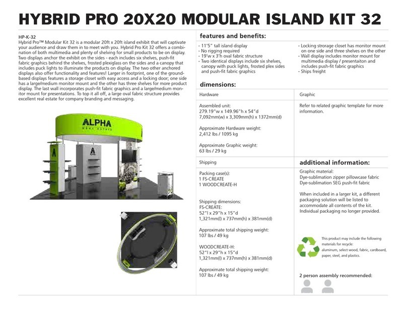
CAMELBACK Displays HYBRID PRO HP-K-32 User manual

CAMELBACK Displays

CAMELBACK Displays HYBRID PRO HP-K-32 User manual

CAMELBACK Displays 8 FOOT VALANCE User manual

CAMELBACK Displays

CAMELBACK Displays 8 FOOT VALANCE User manual

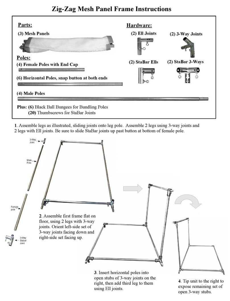
CAMELBACK Displays Zig-Zag Mesh User manual

CAMELBACK Displays

CAMELBACK Displays Zig-Zag Mesh User manual

Popular Indoor Furnishing manuals by other brands

PATIOJOY HW70812-4 Assembly instructions

PATIOJOY

PATIOJOY HW70812-4 Assembly instructions

Kvik H925-060-050-040 Assembly manual

Kvik

Kvik H925-060-050-040 Assembly manual

Manutan A152466 user guide

Manutan

Manutan A152466 user guide

NEXERa 103632 Assembly instructions

NEXERa

NEXERa 103632 Assembly instructions

Zanzini Armario 08830200 instruction manual

Zanzini

Zanzini Armario 08830200 instruction manual

Delta Children babyGap Legacy 6 Drawer Dresser instructions

Delta Children

Delta Children babyGap Legacy 6 Drawer Dresser instructions

Argos 1838800 Assembly instructions

Argos

Argos 1838800 Assembly instructions

National Alloy Assembly instruction

National

National Alloy Assembly instruction

Häfele FITT-10111 Assembly guide

Häfele

Häfele FITT-10111 Assembly guide

Dorel Asia OTTOMAN DA021 Instruction booklet

Dorel Asia

Dorel Asia OTTOMAN DA021 Instruction booklet

WIEMANN Catania 991673 manual

WIEMANN

WIEMANN Catania 991673 manual

FMD Furniture BANDOL 3 Assembly instruction

FMD Furniture

FMD Furniture BANDOL 3 Assembly instruction

Enwork Solano Flip Table installation guide

Enwork

Enwork Solano Flip Table installation guide

VIPACK SCLB200 Assembly instructions

VIPACK

VIPACK SCLB200 Assembly instructions

Atlantic Furniture TWIN FULL Assembly instructions

Atlantic Furniture

Atlantic Furniture TWIN FULL Assembly instructions

fantastic furniture Como Bed Head Double manual

fantastic furniture

fantastic furniture Como Bed Head Double manual

Steelcase Turnstone Jack Chair Assembly instructions

Steelcase

Steelcase Turnstone Jack Chair Assembly instructions

Williams-Sonoma TOLSON Assembly instructions

Williams-Sonoma

Williams-Sonoma TOLSON Assembly instructions

manuals.online logo
manuals.online logoBrands
  • About & Mission
  • Contact us
  • Privacy Policy
  • Terms and Conditions

Copyright 2025 Manuals.Online. All Rights Reserved.