Camille Bauer LINAX A325 User manual

Operating instructions
Video recorder
LINAX A325

Brief overview
Integrated Operating Instructions
The unit's simple control system enables you to perform commissioning for many applications without the
need for hardcopy operating instructions. Your unit displays instructions at the push of a button directly
on screen. These instructions are nevertheless delivered with the unit - they supplement the Operating
Instructions in the unit. Anything that is not described directly at the unit by plain text or menus is
explained here.
Fig. 1: Variable softkey (e.g. to call up the internal Help function in the Setup mode)
Index
A very extensive index can be found at the end of these Operating Instructions. It acts as a complement
to the table of contents and helps you find special terms and functions.

Advanced Graphic Data Manager
3

Advanced Graphic Data Manager Table of contents
4
Table of contents
1 Safety instructions . . . . . . . . . . . . . . . . 5
1.1 Designated use . . . . . . . . . . . . . . . . . . . . . . . . . . . . 5
1.2 Installation, commissioning and operation . . . . . . . . 5
1.3 Operational safety . . . . . . . . . . . . . . . . . . . . . . . . . . 5
1.4 Safety information for table version (option) . . . . . . 5
1.5 IT security . . . . . . . . . . . . . . . . . . . . . . . . . . . . . . . 5
1.6 Return . . . . . . . . . . . . . . . . . . . . . . . . . . . . . . . . . . 6
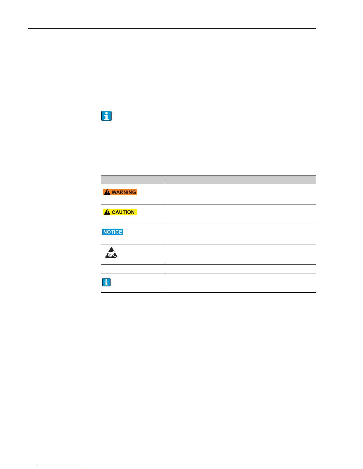
1.7 Notes on safety conventions and icons . . . . . . . . . . 6
2 Identification . . . . . . . . . . . . . . . . . . . . 7
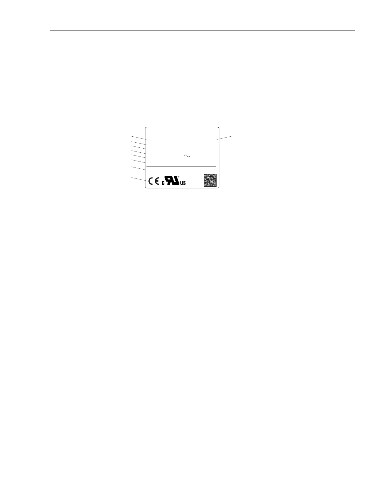
2.1 Device designation . . . . . . . . . . . . . . . . . . . . . . . . . 7
2.2 Scope of delivery . . . . . . . . . . . . . . . . . . . . . . . . . . 7
2.3 Certificates and approvals . . . . . . . . . . . . . . . . . . . . 7
3 Installation . . . . . . . . . . . . . . . . . . . . . . 8
3.1 Incoming acceptance, transport, storage . . . . . . . . . 8
3.2 Installation conditions . . . . . . . . . . . . . . . . . . . . . . . 8
3.3 Installation instructions . . . . . . . . . . . . . . . . . . . . . . 8
3.4 Post-installation check . . . . . . . . . . . . . . . . . . . . . 10
4 Wiring. . . . . . . . . . . . . . . . . . . . . . . . . 10
4.1 Quick wiring guide . . . . . . . . . . . . . . . . . . . . . . . . 10
4.2 Terminal assignment . . . . . . . . . . . . . . . . . . . . . . 13
4.3 Interface connection . . . . . . . . . . . . . . . . . . . . . . . 18
4.4 Degree of protection . . . . . . . . . . . . . . . . . . . . . . . 22
4.5 Post-connection check . . . . . . . . . . . . . . . . . . . . . 22
5 Operation . . . . . . . . . . . . . . . . . . . . . . 22
5.1 Quick operating guide . . . . . . . . . . . . . . . . . . . . . 22
5.2 Display and operating elements . . . . . . . . . . . . . . . 23
5.3 Entering text and numbers . . . . . . . . . . . . . . . . . . 25
5.4 Overview of the symbols used . . . . . . . . . . . . . . . 25
5.5 Confirming error messages . . . . . . . . . . . . . . . . . . 26
5.6 Communication; installing the PC software . . . . . . 27
6 Commissioning and use during operation
31
6.1 Installation check . . . . . . . . . . . . . . . . . . . . . . . . . 31
6.2 Switching on the device . . . . . . . . . . . . . . . . . . . . 31
6.3 Setup . . . . . . . . . . . . . . . . . . . . . . . . . . . . . . . . . . 32
6.4 The Setup screen (in the main menu) . . . . . . . . . . 37
6.5 Use during operation - the "Extras" menu . . . . . . . 83
6.6 Use during operation - the main menu . . . . . . . . . 97
6.7 Settings for the mathematics channels, Formula editor
107
6.8 Meeting the requirements of 21 CFR 11 . . . . . . . 113
6.9 Measured value storage . . . . . . . . . . . . . . . . . . . 114
6.10 Data analysis and visualization using PC analysis
software . . . . . . . . . . . . . . . . . . . . . . . . . . . . . . 115
7 Maintenance . . . . . . . . . . . . . . . . . . . 117
7.1 Software update via the PC software supplied . . . 117
8 Accessories . . . . . . . . . . . . . . . . . . . . 119
8.1 Device-specific accessories . . . . . . . . . . . . . . . . . 119
9 Troubleshooting. . . . . . . . . . . . . . . . . 121
9.1 Diagnose/simulation in the main menu . . . . . . . . 121
9.2 Troubleshooting instructions . . . . . . . . . . . . . . . . 121
9.3 System error messages . . . . . . . . . . . . . . . . . . . . 122
9.4 Errors and warnings . . . . . . . . . . . . . . . . . . . . . . 122
9.5 Spare parts . . . . . . . . . . . . . . . . . . . . . . . . . . . . . 126
9.6 Return . . . . . . . . . . . . . . . . . . . . . . . . . . . . . . . . 128
9.7 Disposal . . . . . . . . . . . . . . . . . . . . . . . . . . . . . . . 128
9.8 Software history . . . . . . . . . . . . . . . . . . . . . . . . . 128
10 Technical data . . . . . . . . . . . . . . . . . . 130
10.1 Input . . . . . . . . . . . . . . . . . . . . . . . . . . . . . . . . . 130
10.2 Output . . . . . . . . . . . . . . . . . . . . . . . . . . . . . . . . 132
10.3 Power supply / terminal diagram . . . . . . . . . . . . 134
10.4 Connection data interface, communication, operation .
135
10.5 Performance characteristics . . . . . . . . . . . . . . . . . 137
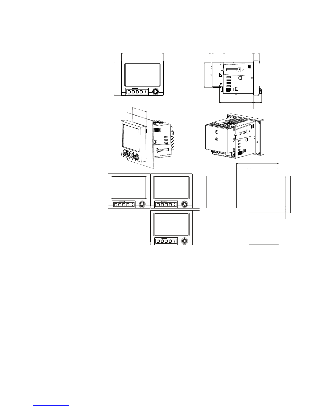
10.6 Installation . . . . . . . . . . . . . . . . . . . . . . . . . . . . . 137
10.7 Environment . . . . . . . . . . . . . . . . . . . . . . . . . . . 137
10.8 Mechanical construction . . . . . . . . . . . . . . . . . . . 138
10.9 Human interface . . . . . . . . . . . . . . . . . . . . . . . . . 141
10.10 Certificates and approvals . . . . . . . . . . . . . . . . . . 145
10.11 Accessories . . . . . . . . . . . . . . . . . . . . . . . . . . . . . 145
10.12 Documentation . . . . . . . . . . . . . . . . . . . . . . . . . . 145
Index . . . . . . . . . . . . . . . . . . . . . . . . . . . . . 147

Advanced Graphic Data Manager Safety instructions
5
1 Safety instructions
1.1 Designated use
This unit is designed for the electronic acquisition, display, recording, analysis, remote transmission
and archiving of analog and digital input signals in non-hazardous areas.
• The unit is designed for installation in a panel or a cabinet and may only be operated in an installed
state.
• The manufacturer does not accept liability for damage caused by improper or non-designated use.
The unit can cause danger if used improperly or other than intended.
1.2 Installation, commissioning and operation
• The unit may only be installed, connected, commissioned and serviced by qualified and
authorized expert staff (e.g. electrical technicians) strictly adhering to the instructions contained
in this manual, the applicable norms, legal regulations and certificates (depending on the
application).
• These experts must have read and understood this manual and follow the instructions it contains.
• The unit may only be modified or repaired if expressly permitted in the Operating Instructions.
• Damaged units which could pose a source of danger may not be put into operation and must be
marked as defective.
• Primarily observe local regulations regarding opening and repairing electrical units.
1.3 Operational safety
• The unit is safely built and tested according to state-of-the-art technology and has left the factory
in perfect condition as regards technical safety. The applicable regulations and European standards
have been taken into account.
• Please observe the technical data on the nameplate! The nameplate is on the left-hand side of the
housing.
Repairs
Repairs that are not described in these Operating Instructions must only be carried out directly by
the manufacturer or by the service department.
Electromagnetic compatibility
The measuring system meets the general safety requirements of IEC 61010 and the EMC
requirements of IEC 61326.
Technical improvement
The manufacturer reserves the right to adapt technical data to the most up-to-date technical
developments without any special announcement. Ask your supplier for information about activities
and possible extensions to these Operating Instructions.
1.4 Safety information for table version (option)
Safety information:
The mains plug should only be inserted into a socket with a ground contact.
The protective effect may not be suspended by an extension cable without a protective ground.
Relay outputs: U (max) = 30 V rms (AC) / 60 V (DC)
1.5 IT security
We only provide a warranty if the device is installed and used as described in the Operating
Instructions. The device is equipped with security mechanisms to protect it against any inadvertent
changes to the device settings.

Safety instructions Advanced Graphic Data Manager
6
IT security measures in line with operators' security standards and designed to provide additional
protection for the device and device data transfer must be implemented by the operators
themselves.
1.6 Return
For a return, e.g. in case of repair, the device must be sent in protective packaging. The original
packaging offers the best protection. Repairs must only be carried out by your supplier's service
organization.
1.7 Notes on safety conventions and icons
The safety instructions in these Operating Instructions are labeled with the following safety icons
and symbols:
When sending for repair, please enclose a note with a description of the error and the
application.
Symbol Meaning
A0011190-EN
WARNING!
This symbol alerts you to a dangerous situation. Failure to avoid this situation can
result in serious or fatal injury.
A0011191-EN
CAUTION!
This symbol alerts you to a dangerous situation. Failure to avoid this situation can
result in minor or medium injury.
A0011192-EN
NOTE
This symbol contains information on procedures and other facts which do not result
in personal injury.
ESD - Electrostatic discharge
Protect the terminals from electrostatic discharge. Failure to observe this may result
in destruction or malfunction of parts of the electronics.
A0011193
Additional information, tip

Advanced Graphic Data Manager Identification
7
2 Identification
2.1 Device designation
2.1.1 Nameplate
Compare the nameplate on the top of the unit with the delivery note and with the following
diagram:
Fig. 2: 1. Device tag
2. Order code
3. Serial number
4. Supply voltage, power frequency
5. Power consumption
6. Firmware version
7. Ambient temperature range
8. Unit approvals; 2D matrix code
9. Place and year of manufacture
2.2 Scope of delivery
• Unit (with terminals, as per your order)
• 2 fastening clips
• USB interface cable, length 1.5 m (4.9 ft)
• Optional secure digital (SD) card (card not in device but is supplied.)
• PC operating and configuration software on CD-ROM
• Delivery note
• Multilanguage Brief Operating Instructions as hard copy
Anything missing? Then please inform your supplier.
2.3 Certificates and approvals
An overview of all the certificates and approvals can be found in the Technical Data, Section 10.
2
3
4
100-230 V AC ( 50/60Hz
40VA
FW: XX.XX.XX
±10%)
OSG40-xxxxxxxx
Xxxxxxxxxx
Made in Germany 2014
D-87484 Nesselwang
Ordercode:
Ser. No. :
-10°C (14°F) < Ta < 50°C (122°F)
Graphic Data Manager
8
7
6
1
5
9

Installation Advanced Graphic Data Manager
8
3 Installation
3.1 Incoming acceptance, transport, storage
3.1.1 Incoming acceptance
After receiving the goods, check the following points:
• Is the packaging or the content damaged?
• Is the delivery complete? Compare the goods delivered with what you ordered.
3.1.2 Transport and storage
Observe the following points:
• The unit must be packed in shockproof packaging for storage (and transport). The original
packaging offers the best protection for this.
• The permitted storage temperature is -20 to +60 °C (-4 to 140 °F)
3.2 Installation conditions
Working temperature range:
-10 to 50 °C (22 to 122 °F), max. 75% rel. humidity without condensation.
Impairment of the operating life of the device
To avoid heat accumulation, please always ensure that the unit is sufficiently cooled.
Maintain distance from strong magnetic fields (see Section 10 "Technical data", interference
immunity)
ZPermitted ambient conditions at front: in accordance with unit ingress protection of max. IP65
(with front flap closed)
3.3 Installation instructions
3.3.1 Mounting tool
To install in the control panel, all you need is a screwdriver.

Advanced Graphic Data Manager Installation
9
3.3.2 Panel mounting, Installation dimensions
Fig. 3: Panel mounting and installation dimensions. All dimensions in mm or (inch)
• Installation depth without terminal cover: approx. 158 mm (6.22") (incl. terminals and fastening
clips)
• Installation depth with terminal cover: approx. 197 mm (7,76")
• Panel cutout: 138+1 x 138+1 mm (5.43+0.04 x 5.43+0.04")
• Panel thickness: 2 to 40 mm (0.08 to 1.58")
• Max. viewing angle range: from the display central axis 50° in all directions
• Securing to DIN 43 834
1. Push the unit through the panel cutout from the front. To avoid heat accumulation, we
recommend keeping a distance of >15 mm (>0.59 inch) from the walls and other units.
2. Hold the unit horizontally and then hang the two jack screws into the openings (either as
shown in figure 3 the upper opening on the left and the lower opening on the right side of the
housing, or use the openings on top and bottom of the housing).
3. Tighten the screws on the jack screws equally with a screwdriver such that a secure seal to the
control panel is guaranteed (dynamometric screwdriver: 100 Ncm).
107.1 (4.22)
27
(1.06)
8.77
(0.3)
58
(0.28)
196 (7.72)
20
(0.79) 158 (6.22)
157.4 (6.20)
192.3 (7.57)
37.07
(1.46)
149.2
(5.87)
195.2
(7.69)
5
(0.2)
141 (5.55)
138
(5.43 )
+1
+0.04
138 (5.43)
138 (5.43)

Wiring Advanced Graphic Data Manager
10
3.4 Post-installation check
After panel mounting, please check the following points:
• Is the unit fixed firmly in the center of the control panel cutout?
4 Wiring
4.1 Quick wiring guide
Danger! Electric voltage!
The entire connection of the device must take place while the device is de-energized.
Incorrect power supply can cause malfunctions
The ground connection must be made before all other connections. Any interruption in the ground
can cause danger.
Before commissioning the device, make sure that the supply voltage matches the voltage
specifications on the nameplate.
Provide a suitable switch or power-circuit breaker in the building installation. This switch must be
installed close to the device (so that it is easily accessible) and marked as a circuit breaker.
An overload protection unit (rated current = 10 A) is required for the power cable.
The mixed connection of safety extra-low voltage and dangerous contact voltage to the relay is not
permitted.
4.1.1 Color assignment of the channels
Colors are assigned to the channels in Setup "Application –> Signal groups". 8 predefined colors are
available per group and can be assigned to the desired channels.
• A distance of min. 7 mm (0.28 inch) between the devices has to be observed if aligning
the devices in the Y-direction (vertically above one another).
• The devices can be arranged horizontally beside one another in the X direction without
any spacing between the devices.
• The grid dimension of the panel cutouts for multiple devices must be min. 196.2 mm
(7.72") horizontally and min. 156.2 mm (6.15") vertically (tolerance not considered).
Please also refer to the terminal designation on the rear of the unit.

Advanced Graphic Data Manager Wiring
11
4.1.2 Circuit diagram
Fig. 4: Circuit diagram
Ethernet USB RS 232 / RS 485 Bus Interface
Ch1
Ch2
Ch3
41
…
…
…
…
46
Ch4
31
…
…
…
…
36
21
…
…
…
…
26
11
…
…
…
…
16
Ch5
Ch6
Ch7
81
…
…
…
…
86
Ch8
71
…
…
…
…
76
61
…
…
…
…
66
51
…
…
…
…
56
Ch9
Ch10
Ch11
C1
…
…
…
…
C6
Ch12
B1
…
…
…
…
B6
A1
…
…
…
…
A6
91
…
…
…
…
96
Ch13
Ch14
Ch15
G1
…
…
…
…
G6
Ch16
F1
…
…
…
…
F6
E1
…
…
…
…
E6
D1
…
…
…
…
D6
L/+
N/-
PE
24V
Out
O15
O16
O25
O26
D71
D81
D91
DA1
DB1
DC1
DD1
DE1
GND2
GND2
R11
R12
R13
R41
R42
R51
R52
R61
R62
D11
D21
D31
D41
D51
D61
GND1
+
R21
R22
R31
R32
-
RA
RB
RC
RD
RE
RF
RG
RH
RI
RJ
RK
RL
-
+
-
+
-
+
b) 1 V
£
a) > 1 V
Rel. max. 250 V / 3 A
+
-
a) 0...5 V, 1...5 V, 0...10 V, +/- 10 V, +/- 30 V
b) 0...1 V, +/- 150 mV, +/- 1 V
L+ N- PE
100-230 VAC
(±10%)
50 / 60 Hz
12-24 VDC
>5 mA
+
+
_
RTD
I
U
TC
0...20 mA, 4...20 mA, 0...5 mA
J, K, T, N, L, D, C, B, S, R
U max. = 24 V
+
_
12-24 VDC
24 V AC/DC
(-10%; +15%)
50 / 60 Hz
24V Out: max. 250 mA
Dx1
+
-
LOW = 0...7 mA
HIGH = 13...20 mA
U max. = 2.5 V
15
69
>30 µs
>20 ms
RS 232
2
2
2
2
3
3
3
3
5
5
5
5
1
1
1
1
5
5
13
13
6
6
14
14
9
9
25
25
7
7
RS 485
RxD/TxD(+)
RL
RxD/TxD(-)
R=
L
8
9
89
89
89
89
x2x1 x3 x4 x5 x6
x2x1 x3 x4 x5 x6
Dx1
GNDx
24 V +
Dx1
GNDx
24 V -
-
GNDx
Dx1
GNDx
10k
O15
O16
O25
O26
+-+-
12
0...20 mA;
4...20 mA
+-+-
12
Pt46, Pt50, Pt100,
Pt500, Pt1000,
Cu50, Cu53, Cu100
x2x1 x3 x4 x5 x6 x2x1 x3 x4 x5 x6
+
-
24 V
x2x1 x3 x4 x5 x6
R=1.2 k
a) U max. = 35 V
b) U max. = 24 V
U max. = 2.5 V
(Volt drop 1 V, Ri50 Ohm)££
Further units
Cable
resistance
Power supply
Digital in (D)
To PC: Cable with
9 pol. Sub-D plug
RxD - 3 GND - 5
TxD - 2
To PC: Cable with
25 pol. Sub-D
plug
To modem: Cable with
9 pol. Sub-D socket
To modem: Cable with
25 pol. Sub-D socket
Analog inputs
LED
yellow
LED
green
Pulse/
frequency
Power supply slot
Slot 5
Slot 4
Slot 3
Slot 2
Slot 1 )
Interface slot
(standard)
1-4 (option
analog input 17-20 or digital-I/O (option)
analog input 13-16 (option)
analog input 9-12 (option)
analog input 5-8 (option)
analog input
Analog
outputs (O)
(Selectable in unit setup)
Pulse
Depending on the order, slot 5 can be assigned different cards (analog or digital inputs/
outputs). When connecting, please take the corresponding terminal diagram into account.

Wiring Advanced Graphic Data Manager
12
4.1.3 Auxiliary voltage output as transmitter power supply for 2-wire
sensors
Fig. 5: Connecting the auxiliary voltage output when using as transmitter power supply for 2-wire sensors in the
current measuring range
– External display: e.g. Loop-powered indicator
– Sensor 1: e.g. Temperature field transmitter
– Sensor 2: e.g. Digital pressure transmitter
_
+
-
Y
+
-
Y
+
+
_
24 V Out: max. 250 mA
On connecting channels 3-16
see terminal connections Ch1-2
Sensor 1
Sensor 2
External display
(optional)

Advanced Graphic Data Manager Wiring
13
4.1.4 Auxiliary voltage output as transmitter power supply for 4-wire
sensors
Fig. 6: Connecting the auxiliary voltage output when using as transmitter power supply for 4-wire sensors in the
current measuring range
– External display: e.g. Loop-powered indicator
– Sensor 1: e.g. Flowmeter
– Sensor 2: e.g. Level measurement
4.2 Terminal assignment
4.2.1 Cable specification, spring terminals
All connections on the rear of the unit are designed as screw or spring terminal blocks with reverse
polarity protection. This makes the connection very quick and easy. The spring terminals are
actuated with a slotted screwdriver (size 0).
Please note the following when connecting:
• Wire cross-section, digital I/O, RS485 and analog inputs: max. 1.5 mm2(14 AWG) (spring
terminals)
• Wire cross-section, power supply: max. 2.5 mm2(13 AWG) (screw terminals)
• Wire cross-section, relays: max. 2.5 mm2(13 AWG) (spring terminals)
• Stripped length: 10 mm (0.39 inch), 6 mm (0.24 inch) for power terminal
_
+
-
Y
+
+_
+
-
Y
24 V Out: max. 250 mA
On connecting channels 3-16
see terminal connections Ch1-2
Sensor 1
Sensor 2
Ext. display (optional)
If high-energy transients occur when using long signal cables, we recommend connecting
a suitable overvoltage protection (e.g. E+H HAW562).
Use shielded signal lines for serial interfaces!
No ferrules have to be used when connecting flexible wires to spring terminals.

Wiring Advanced Graphic Data Manager
14
4.2.2 Supply voltage (power supply slot)
4.2.3 Relay (power supply slot)
Power unit type Terminal
100-230 V AC L+ N- PE
Phase L Zero conductor N Ground
24 V AC/DC L+ N- PE
Phase
L or +
Zero conductor N or – Ground
Type Terminal
R11 R12 R13 Rx1 Rx2
Alarm relay 1 Changeover
contact
Normally
closed contact
(NC)1)
1) NC = normally closed
Normally open
contact (NO)2)
2) NO = normally open
Relay 2 - 6 Switching
contact
Normally open
contact (NO)2)
The opening and closing function (= activation or deactivation of the relay coil) in the event
of a limit value can be defined in the setup "Setup -> Outputs -> Relay -> Relay x". If the
power fails, the relay assumes its quiescent switching position regardless of the
programming.
If there are several reasons for triggering a relay (e.g. 2 different limit values), this must be
set to "Collective relay" under "Setup -> Outputs -> Relay -> Relay x".
L+
N-
PE
R11
R12
R13
R41
R42
R51
R52
R61
R62
R21
R22
R31
R32

Advanced Graphic Data Manager Wiring
15
4.2.4 Digital inputs (power supply slot)
4.2.5 Digital inputs (optional: slot 5)
If the auxiliary voltage is to be used for the digital inputs, the "–" terminal of the 24 V
auxiliary voltage has to be connected to the "GND1" terminal.
Type Terminal
D11 D21 D31 D41 D51 D61 GND1 (–) (+)
Digital
input 1 - 6
Digital input
1 (+)
Digital input
2 (+)
Digital input
3 (+)
Digital input
4 (+)
Digital input
5 (+)
Digital input
6 (+)
Ground (-)
for digital
inputs 1-6
Auxiliary
voltage
output, not
stabilized,
max. 250
mA
Ground +24 V
±15%
24V
Out
D11
D21
D31
D41
D51
D61
GND1
+
-
If the auxiliary voltage is to be used for the digital inputs, the "–" terminal of the
24 V auxiliary voltage has to be connected to the "GND2" terminal.
Type Terminal
D71 D81 D91 DA1 DB1 DC1 DD1 DE1 GND2 GND2
Digital
input 7-
14
Digital
input 7
Digital
input 8
Digital
input 9
Digital
input 10
Digital
input 11
Digital
input 12
Digital
input 13
Digital
input 14
Ground
for digital
inputs 7-
14
Ground
for digital
inputs 7-
14
D71
D81
D91
DA1
DB1
DC1
DD1
DE1
GND2
GND2

Wiring Advanced Graphic Data Manager
16
4.2.6 Analog outputs (optional: slot 5)
4.2.7 Relay (optional: slot 5)
Type Terminal
O15 O16 O25 O26
Analog output 1-2 Analog output
1 (+)
Ground analog
output 1 (–)
Analog output
2 (+)
Ground analog
output 2 (–)
O15
O16
O25
O26
Type Terminal
RA RB RC RD RE RF RG RH RI RJ RK RL
Relay
7-12
Switchi
ng
contact,
relay
7
Normall
y open
contact
(NO)1)
relay 7
Switchi
ng
contact,
relay
8
Normall
y open
contact
(NO) 2)
relay 8
Switchi
ng
contact,
relay
9
Normall
y open
contact
(NO) 2)
relay 9
Switchi
ng
contact,
relay
10
Normall
y open
contact
(NO) 2)
relay 10
Switchi
ng
contact,
relay
11
Normall
y open
contact
(NO) 2)
relay 11
Switchi
ng
contact,
relay
12
Normall
y open
contact
(NO) 2)
relay 12
1) NO = normally open
RA
RB
RC
RD
RE
RF
RG
RH
RI
RJ
RK
RL
The opening and closing function (= activation or deactivation of the relay coil) in the event
of a limit value can be defined in the setup "Setup -> Outputs -> Relay -> Relay x".
If there are several reasons for triggering a relay (e.g. 2 different limit values), this must be
set to "Collective relay" under "Setup -> Outputs -> Relay -> Relay x".

Advanced Graphic Data Manager Wiring
17
4.2.8 Analog inputs (slot 1-5)
The first digit (x) of the two-digit terminal number corresponds to the related channel (e.g. Ch1:
11, 12, 13, 14, 15, 16):
Type Terminal
x1 x2 x3 x4 x5 x6
Current/pulse/
frequency
input1)
1) If a universal input is used as a frequency or pulse input and the voltage is >2.5 V, a resistance must be used in series
connection with the voltage source. Example: 1.2 kOhm series resistance at 24 V
(+) (–)
Voltage >1 V (+) (–)
Voltage 1 V (+) (–)
Resistance
thermometer
RTD (2-wire)
(A) (B)
Resistance
thermometer
RTD (3-wire)
(A) b (sense) (B)
Resistance
thermometer
RTD (4-wire)
(A) a (sense) b (sense) (B)
Thermocouples
TC
(+) (–)
Chx
x1
x2
x3
x4
x5
x6

Wiring Advanced Graphic Data Manager
18
4.3 Interface connection
4.3.1 USB at the front of the unit
Fig. 7: Front of unit with open flap/keyboard
1: USB A socket "host" e.g. for USB memory stick, external keyboard, bar code reader or printer
2: USB B socket "function" e.g. to connect to PC or laptop
3: LED at SD slot. Yellow LED lit when the unit writes to the SD card or reads it.
4: Slot for SD card
5: Navigator
1 x USB connection, type A (host)
A USB 2.0 connection is available on a shielded USB A socket at the front of the unit. A USB stick
as a memory medium, a keyboard, a USB hub, a bar code reader or a printer (PCL5c or higher) can
be connected to this interface.
1 x USB connection, type B (function)
A USB 2.0 connection is available on a shielded USB B socket at the front of the unit. This can be
used to connect the unit for communication with a laptop for example.
4.3.2 USB at the rear of the unit
2 x USB connection, type A (host) (interface slot)
Two USB 2.0 connections are available on shielded USB A sockets at the rear of the unit. A USB
stick as a memory medium, a keyboard, a USB hub, a bar code reader or a printer (PCL5c or higher)
can be connected to these interfaces.
3
1 2 4
5
• The USB 2.0 connections are compatible with USB 1.1, i.e. communication is possible.
• The assignment of the USB ports corresponds to the standard such that shielded standard
cables with a maximum length of 3 meters (9.8 ft) can be used here.
• Multiple USB sticks cannot be operated simultaneously. The USB stick that was first
connected has priority.

Advanced Graphic Data Manager Wiring
19
4.3.3 Points to note concerning USB units
!Note!
Requirements with regard to an external USB hub
If USB units are deactivated due to the 500 mA unit limit, such units can be connected by means
of a USB hub. Only active USB hubs (i.e. hubs with their own power supply) can be connected to
the unit. Hubs with an "overcurrent protection" are recommended. A maximum of 1 hub can be
connected to the unit.
Requirements with regard to the USB stick
USB sticks supported: 256 MB, 512 MB, 1 GB and 2 GB. It cannot be ensured that USB sticks from
all manufacturers will work perfectly. For this reason, an "Industrial Grade" SD card is
recommended for safe data recording (see Accessories).
Requirements with regard to an external USB keyboard
The system only supports keyboards which can be addressed using generic drivers (HID keyboard
(human interface unit)). Special keys are not supported (e.g. Windows keys). Users can only enter
characters that are available in the entry character set of the unit. All unsupported characters are
rejected. It is not possible to connect a wireless keyboard.
The following keyboard assignments are supported: DE, CH, FR, USA, UK, IT.
See setting under "Setup -> System -> Keyboard".
Requirements with regard to an external USB bar code reader
The connected bar code reader has to act like a HID keyboard (human interface unit) (universal
keyboard driver). The bar code reader must complete every bar code with a carriage return (0x0D)
+ line feed (0x0A).
Before connecting the bar code reader to the unit, it should be checked at a PC:
1. Connect the bar code reader and wait until Microsoft Windows®recognizes the unit as a HID
keyboard and installs it (check with the Windows unit manager).
2. Configure the bar code reader as specified in the Operating Instructions of the bar code reader.
3. Start the Notepad (editor).
4. Using the bar code reader, read in a bar code (as it is used later) and check it.
5. Only connect the bar code reader to the unit once the bar code reader has been correctly
configured and tested on the PC.
6. Select the character set at the unit under "Setup -> System -> Bar code reader -> Character
set". The following character sets are supported: DE, CH, FR, USA, UK, IT.
Note: This setting has to be identical to the configuration of the bar code reader!
The system only reads characters that are available in the entry character set of the unit. All
other characters are rejected.
7. The bar code reader should also be tested at the unit via "Main menu -> Diagnosis/simulation
-> Simulation -> Test bar code reader".
If problems arise, please contact the manufacturer of the bar code reader.
Reference list: Datalogic Gryphon D230, Metrologic MS5100 Eclipse Series, Symbol LS2208
The USB units are detected by the "plug-and-play" function. If several units of the same type
(e.g. printer) are connected, only the first USB unit connected is available.
Settings for the USB units are made in the setup.
A maximum of 8 external USB units (incl. USB hub) can be connected if they do not exceed
the maximum load of 500 mA. If overloaded, the corresponding USB units are
automatically disabled.

Wiring Advanced Graphic Data Manager
20
Requirements with regard to an external USB printer
The printer must support PCL5c (or higher). Laser jet and ink jet printers are supported. The
printouts are always color printouts (if supported by the printer). The printout has different shades
of gray if you use a black/white printer.
Reference list: HP Color LaserJet CP1515n, HP Color LaserJet Pro CP1525n, Kyocera FS-C5015N
!Note!
4.3.4 RS232/RS485 interface
RS232/RS485 connection
A combined RS232/RS485 connection is available on a shielded SUB D9 socket at the rear of the
unit. This can be used for data or program transfer and to connect a modem. For communication
via modem, we recommend an industrial modem with a watchdog function.
"Caution!
Only one interface can be used at any one time (RS232 or RS485). Choose the interface to be used
under “Extras - Serial Interface”.
4.3.5 Ethernet
In principle, a unit equipped with an internal Ethernet interface can be integrated into a PC network
(TCP/IP Ethernet). The unit(s) can be accessed by any of the PCs in the network using the PC
operating and configuration software supplied.
Using DHCP,1) the fully automated integration of a new unit into an existing network is possible
without any additional configuration. Normally, only automatic IP address acquisition has to be
configured at the client. When the unit is started in the network, it can automatically get the IP
GDI printers are not supported!
Pin of the SUB-D9 socket
123456789
RS232
assignmen
t
TxD (data
output)
RxD (data
input)
GND
Fig. 8: RS232 assignment
Unoccupied connections should be left empty. The maximum cable length is 2
m (6.6 ft).
RS485
assignmen
t
GND RxD/TxD – RxD/TxD +
Fig. 9: RS485 assignment
Unoccupied connections should be left empty. The maximum cable length is
1000 m (3280 ft).
54321
9876
54321
9876
GDI printers are not supported!
1) DHCP: In conjunction with an appropriate server, the Dynamic Host Configuration Protocol (DHCP) makes it possible to dynamically assign an IP address and
additional configuration parameters of a unit in a network (e.g. Internet or LAN).
Table of contents