Camille Bauer Metrawatt AG Consignes de sécurité V604s, VB604s et VQ604 5
SINEAX V604s,
VB604s, VQ604s
Convertisseur de mesure
multifonctionnel
Les instructions de sécurité devant être impérativement respec-
tées sont indiquées dans le présent document via les symboles
suivants:
À lire impérativement avant d’utiliser l’appareil
Pour garantir le bon fonctionnement, sans risque
de l’appareil, il est impératif que vous ayez lu et
compris les consignes de sécurité ainsi que le
manuel de l’utilisateur !
Cet appareil ne doit être manipulé que par un per-
sonnel formé, qui connaît l’appareil et est habilité
à entreprendre des travaux dans des installations
techniques.
Vous devez impérativement mettre l’appareil hors
service dès qu’un fonctionnement sans risque
n’est plus assuré (en cas d’endommagement visible
par exemple). Débranchez pour ce faire toutes les
connexions. Renvoyez l’appareil à notre usine ou à
un service de maintenance agréé.
Toute intervention sur l’appareil annule la garantie!
Contenu de la livraison
1 SINEAX V604s, VB604s ou VQB604s
1 Consignes de sécurité 168501
Brève présentation de l’appareil
Le SINEAX V604s, VB604s ou VQ604s est un convertisseur de mesure
multifonctionnel programmable pour montage sur rails à chapeau. Il y a
séparation galvanique entre entrée, sortie, bus et alimentation auxiliaire.
La programmation et la communication sont assurées par une interface
Modbus.
Données techniques
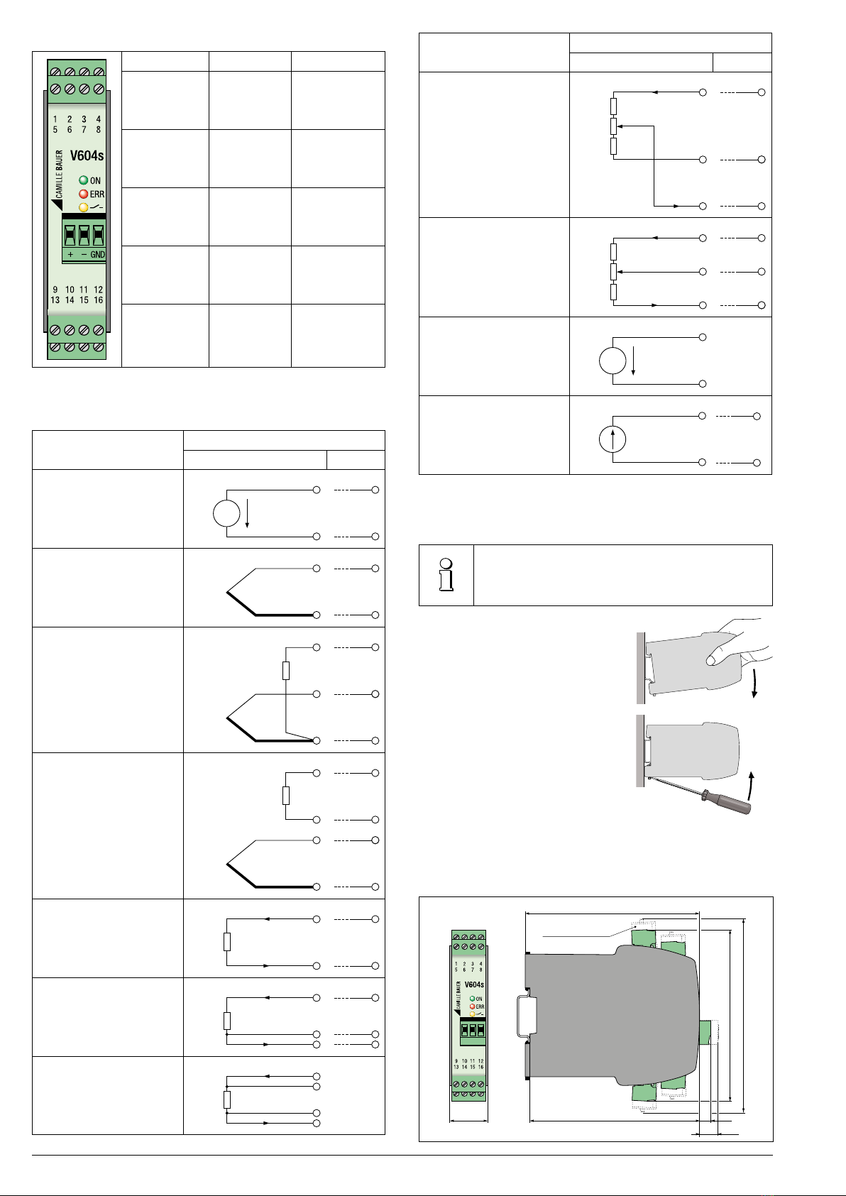
Entrée de mesure
2 entrées de mesure, à liaison galvanique. Respectez les instructions de
branchement des 2capteurs stipulées dans le manuel de l’utilisateur!
Type de mesure Plage de mesure Marge minimale
Tension CC [mV] –1000 … 1000 mV 2 mV
Tension CC [V] * –600 … 600 V 1) >1 V
Intensité CC [mA] –50 … 50 mA 0,2 mA
Résistance [Ω] 0 … 5000 Ω 8 Ω
RTD Pt100 –200 ... 850 °C 20 K
RTD Ni100 –60 ... 250 °C 15 K
TC type B 0 ... 1820 °C 635 K
TC type E –270 ... 1000 °C 34 K
TC type J –210 ... 1200 °C 39 K
TC type K –270 ... 1372 °C 50 K
TC type L –200 ... 900 °C 38 K
TC type N –270 ... 1300 °C 74 K
TC type R –50 ... 1768 °C 259 K
TC type S –50 ... 1768 °C 265 K
TC type T –270 ... 400 °C 50 K
TC type U –200 ... 600 °C 49 K
TC Type W5Re-W26Re 0 ... 2315 °C 135 K
TC Type W3Re-W25Re 0 ... 2315 °C 161 K
* pas avec VB604s et VQ604s
1) Pour les versions anciennes de l'appareil, la plage de mesure est limitée
à -300...300 V. Attention, vérifiez la version de l'appareil sur la plaque
d'indentification ou avec le logiciel CB-Manager software.
Les appareils doivent être éliminés uniquement
conformément à la réglementation en vigueur!
Sorties
2 sorties analogiques, à liaison galvanique, masse commune. Sortie
de tension ou de courant pour V604s/VB604s configurable par logi-
ciel, pour VQ604s seulement dans le type d’appareil correspondent.
Courant
continu
Plage ± 20mA, tension apparente 12V
Tension en circuit ouvert < 20V
Limitation max. ±22mA
Tension
continu
Plage ±10 V,
charge max.: V604s/VB604s: 20mA, VQ604s: 0,02 mA
Limitation du courant env. 30mA
Limitation max. ±11V
Sortie de contact relais
Variante Relais:
Contact 1 pôle, contact à fermeture (NO)
Puissance de commutation CA: 2A/250V, CC: 2A/30V
Variante sortie numérique*:
Contact Transistor, contact à fermeture (NO)
Puissance de commutation max. 27VDC/27mA
Raccordement du bus/de programmation
Interface, protocole RS485, Modbus RTU
Alimentation auxiliaire
Tension nominale UNTolérance
24 à 230VCC * ± 15%
100 à 230VCA, 50/60 Hz ± 15%
DEL verte = « Power ON » (alimentation)
* En cas de tension de l’alimentation auxiliaire > 125VCC, il est
impératif d’équiper le circuit de l’alimentation auxiliaire d’un
fusible externe.
Raccordements électriques
Leraccordement deslignes électriquesse fait viades bornes enfichables
a vis ou a ressort, appropriées pour des sections de fil de 2,5mm²max.
Avanttoutraccordement,s’assurerimpérativement
que toutes les lignes sont hors tension!
Danger potentiel: haute tension.
Il est impératif…
… de respecter les données indiquées sur la plaque si-
gnalétique!
Un commutateur, bien identifié et facilement accessible, est prévu
à proximité de l’appareil pour couper l’alimentation auxiliaire.
À la mise en marche de l’alimentation auxiliaire, la source
d’alimentation auxiliaire doit pouvoir délivrer un courant suffisant
pendant un bref laps de temps (environ 0,3A).
Ilestenoutreimpératifde respecterlesdirectivesenvigueurdanslepays
(par exemple VDE 0100 « Conditions de mise en place d’installations à
courantfortdetensionnominaleinférieureà1000Volt»pourl’Allemagne)
lors de l’installation et du choix du matériau des lignes électriques!
Camille Bauer Metrawatt AG
Aargauerstrasse 7
CH-5610 Wohlen/Suisse
Téléphone +41 56 618 21 11
Télécopie +41 56 618 21 21
www.camillebauer.com
Consignes de sécurité
www.camillebauer.com/vx604s-fr
168501-05 06.17
PM1000752 000 01