1
5
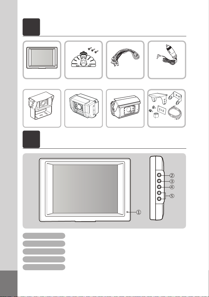
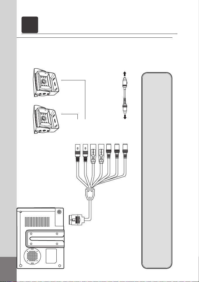
5,6”Rear view system
CM-562
• 8bit MICRO controller
• TFT LCD with high resolution and low reflection
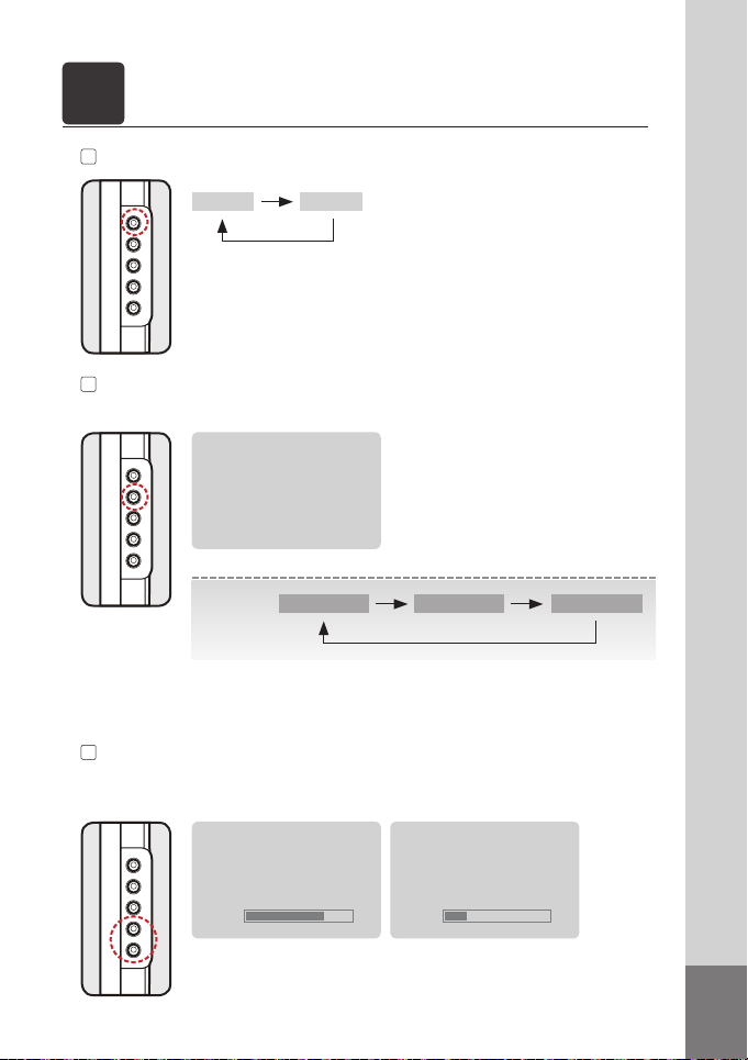
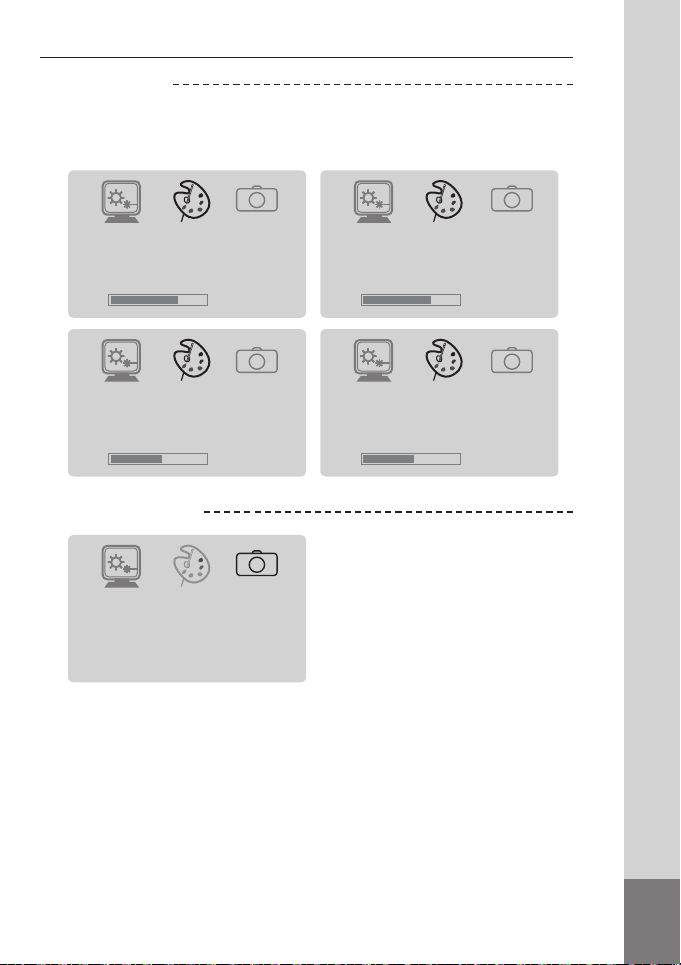
• All functions are displayed on screen (OSD function)
• PWM volume control
• Mode selection function
• Low energy consuming rate
• Language Display Selection (KOR-JPN-GER-ENG-SPA-FRE-ITA)
• 1 Cable solution
• Free voltage (From DC 12V to DC 24V)
• Dimmer selection function
FEATURE
CM-32
• 1/3” COLOUR- CCD Sensor
• 6 IR LEDs for night view
• Built-in microphone
• Built-in heating function
• Waterproof (IP-67)
• Aluminum die-casting housing
CM-42
• 1/3” SONY COLOR CCD image sensor
• 6 pcs of IR LEDs for night view
• Built-in microphone
• Built-in heating function
• Waterproof (IP-67)
• Aluminum die-casting housing
• Night vision using the CdS sensor.
• Automaticall tilt camera lens
CM-46
• 1/3” SONY COLOR CCD image sensor
• 6 pcs of IR LEDs for night.
• Audio Function(Option)
• Heating function Built-in
• Waterproof (IP-67)
• Aluminum die-casting housing
• Night vision using the CdS sensor.
• Automatic shutter open(close) while
moving reverse(forward).