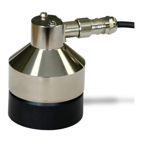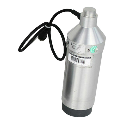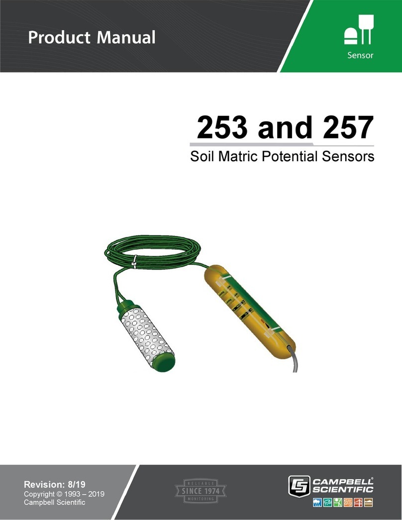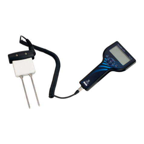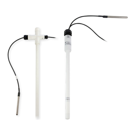
253 AND 253-L SOIL MOISTURE SENSOR
2
3. When removing sensors prior to harvest in
annual crops, do so just after the last
irrigation when the soil is moist. Do not pull
the sensor out by the wires. Careful
removal prevents sensor and membrane
damage.
4. When sensors are removed for winter
storage, clean, dry, and place them in a
plastic bag.
NOTE: The black outer jacket of the cable
is Santoprene®rubber. This compound was
chosen for its resistance to temperature
extremes, moisture, and UV degradation.
However, this jacket will support
combustion in air. It is rated as slow
burning when tested according to U.L. 94
H.B. and will pass FMVSS302. Local fire
codes may preclude its use inside buildings.
3. WIRING
The model 253 sensor is supplied with two green
leads from Watermark. The leads from the
Watermark electrode are connected directly to
the H and L inputs on the AM32 or AM416. The
lead coming from the center of the sensor is
connected to H and the lead from the outer
portion of the sensor to L. The wires can be
differentiated by the grooved strip in one of the
leads of the green wires. On the 253-L, Campbell
Scientific splices a two conductor shielded cable
to the two conductor green cable supplied from
Watermark. The black conductor is connected to
H, the white conductor to L, and the shield wire to
G or . A 1k:resistor at the datalogger is used
to complete the half bridge measurement.
4. MEASUREMENT
Instruction 5, AC Half Bridge, is used to excite
and measure the model 253. Recommended
excitation voltages and input ranges are listed in
Table 1.
TABLE 1. Excitation and Voltage Range
DATALOGGER mV EX RANGE FSR
CODE
21X 500 14 ± 500 mV
CR10 250 14 ± 250 mV
NOTE: Do not use a slow integration time as
sensor polarization errors will occur.
4.1 CALCULATE SENSOR RESISTANCE -
INSTRUCTION 59
Instruction 59, Bridge Transform, is used to
output sensor resistance (Rs). The instruction
takes the AC Half Bridge output (Vs/Vx) and
computes the sensor resistance as follows.
Rs= R1(X/(1-X))
where, X = Vs/Vx (Output from Instruction 5)
A multiplier of 1 should be used to output
sensor resistance (Rs) in terms of k:.
4.2 CALCULATE SOIL WATER POTENTIAL
The datalogger can calculate soil water
potential (bars) from the sensor resistance (Rs)
and soil temperature (Ts). See Table 2.
The need for a precise soil temperature
measurement should not be over emphasized.
Soil temperatures vary widely where placement
is shallow and solar radiation impinges on the
soil surface. A soil temperature measurement
may be needed in such situations, particularly in
research applications. Many applications,
however, require deep placement (5 to 10
inches) in soils shaded by a crop canopy. A
common practice is to assume the air
temperature at sunrise will be close to what the
soil temperature will be for the day.
4.2.1 Linear Relationship
For applications in the range of 0 to 2 bars, the
water potential and temperature responses of
the Watermark can be assumed to be linear
(measurements beyond 1.25 bars have not
been verified, but work in practice).
The following equation normalizes the
resistance measurement to 21qC.
RR
dT
s
21 1 0 018
(. * ) [1]
where
R21 = resistance at 21qC
Rs= the measured resistance
dT = (Ts-21)
Ts= soil temperature
Water potential is then calculated from R21 with
the relationship.
SWP R 0 07407 0 03704
21
.* . [2]
SWP = Soil Water Potential (bars)
