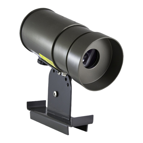
SR50 Sonic Ranging Sensor
5
address for SDI-12 operation or as an option setting for Pulse Train and
ASCII outputs.
The SR50 performs multiple echo processing regardless of output
formats. The SR50 bases every measurement on several readings and
applies an algorithm to improve measurement reliability. When using
SDI-12 or ASCII output, up to 3 targets can be detected with the SR50
provided the difference between their height is > 0.4 meters.
The distance to target readings that are obtained from the sensor are
referenced from the metal mesh on the face of the transducer. The
SR50 has a field of view of approximately 22°. The closest object to the
sensor will be detected if it is within this field of view. If a target is in
motion, the SR50 may reject a reading if the target distance changes at
a rate of 4 centimeters per second or more.
Under most circumstances the SR50 will complete a measurement
within 1 second and begin outputting the data. If the SR50 rejects a
reading or does not detect a target, it will retry. The maximum time limit
to remain in measurement state for retries is 3 seconds. If the reading
is not obtained during this time limit, the SDI-12 and ASCII options will
output zeroes for distance to target and measurement quality numbers
(see below for description of quality numbers). The Pulse Train option
will output a single pulse.
Measurement quality numbers are also available with the SDI-12 and
the ASCII output formats; these give an indication of the measurement
certainty. The quality numbers have no units of measure but can vary
from 162 to 600. Numbers lower than 210 are considered to be
measurements of good quality. A value of zero however, indicates a
reading was not obtained. Numbers greater than 300 indicate that
there is a degree of uncertainty in the measurement. Causes of high
numbers include:
•the sensor is not perpendicular to the target surface
•the target is small and reflects little sound
•the target surface is rough or uneven
•the target surface is a poor reflector of sound (low density snow)
It is not necessary to make use of the quality numbers but they can
provide additional information such as an indication of surface density in
snow monitoring applications.
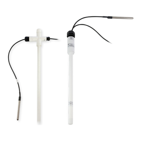
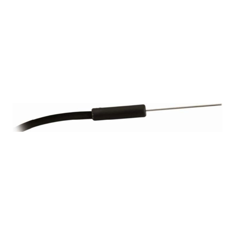
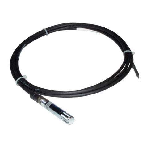
The SR50 does not include a temperature sensor to compensate for
variations in air temperature. Campbell Scientific recommends the
Model 107 air temperature probe for this purpose. A radiation shield
may be required. Temperature compensation must be applied to the
sensor output using the following formula:
FORMULA 1. Temperature Compensation
