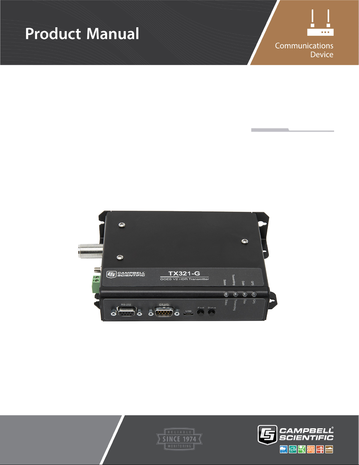
Campbell TX321 User manual

TX321
Transmitter
Revision: 5/19
Copyright © 2000 – 2019
Campbell Scientific


Guarantee
This equipment is guaranteed against defects in materials and workmanship.
We will repair or replace products which prove to be defective during the
guarantee period as detailed on your invoice, provided they are returned to us
prepaid. The guarantee will not apply to:
Equipment which has been modified or altered in any way without the
written permission of Campbell Scientific
Batteries
Any product which has been subjected to misuse, neglect, acts of God or
damage in transit.
Campbell Scientific will return guaranteed equipment by surface carrier
prepaid. Campbell Scientific will not reimburse the claimant for costs incurred
in removing and/or reinstalling equipment. This guarantee and the Company’s
obligation thereunder is in lieu of all other guarantees, expressed or implied,
including those of suitability and fitness for a particular purpose. Campbell
Scientific is not liable for consequential damage.
Please inform us before returning equipment and obtain a Repair Reference
Number whether the repair is under guarantee or not. Please state the faults as
clearly as possible, and if the product is out of the guarantee period it should
be accompanied by a purchase order. Quotations for repairs can be given on
request. It is the policy of Campbell Scientific to protect the health of its
employees and provide a safe working environment, in support of this policy a
“Declaration of Hazardous Material and Decontamination” form will be
issued for completion.
When returning equipment, the Repair Reference Number must be clearly
marked on the outside of the package. Complete the “Declaration of
Hazardous Material and Decontamination” form and ensure a completed copy
is returned with your goods. Please note your Repair may not be processed if
you do not include a copy of this form and Campbell Scientific Ltd reserves
the right to return goods at the customers’ expense.
Note that goods sent air freight are subject to Customs clearance fees which
Campbell Scientific will charge to customers. In many cases, these charges are
greater than the cost of the repair.
Campbell Scientific Ltd,
80 Hathern Road,
Shepshed, Loughborough, LE12 9GX, UK
Tel: +44 (0) 1509 601141
Fax: +44 (0) 1509 270924
Email: support@campbellsci.co.uk
www.campbellsci.co.uk


PLEASE READ FIRST
About this manual
Please note that this manual was originally produced by Campbell Scientific Inc. primarily for the North
American market. Some spellings, weights and measures may reflect this origin.
Some useful conversion factors:
Area: 1 in2(square inch) = 645 mm2
Length: 1 in. (inch) = 25.4 mm
1 ft (foot) = 304.8 mm
1 yard = 0.914 m
1 mile = 1.609 km
Mass: 1 oz. (ounce) = 28.35 g
1 lb (pound weight) = 0.454 kg
Pressure: 1 psi (lb/in2) = 68.95 mb
Volume: 1 UK pint = 568.3 ml
1 UK gallon = 4.546 litres
1 US gallon = 3.785 litres
In addition, while most of the information in the manual is correct for all countries, certain information
is specific to the North American market and so may not be applicable to European users.
Differences include the U.S standard external power supply details where some information (for
example the AC transformer input voltage) will not be applicable for British/European use. Please note,
however, that when a power supply adapter is ordered it will be suitable for use in your country.
Reference to some radio transmitters, digital cell phones and aerials may also not be applicable
according to your locality.
Some brackets, shields and enclosure options, including wiring, are not sold as standard items in the
European market; in some cases alternatives are offered. Details of the alternatives will be covered in
separate manuals.
Part numbers prefixed with a “#” symbol are special order parts for use with non-EU variants or for
special installations. Please quote the full part number with the # when ordering.
Recycling information
At the end of this product’s life it should not be put in commercial or domestic refuse but
sent for recycling. Any batteries contained within the product or used during the
products life should be removed from the product and also be sent to an appropriate
recycling facility.
Campbell Scientific Ltd can advise on the recycling of the equipment and in some cases
arrange collection and the correct disposal of it, although charges may apply for some
items or territories.
For further advice or support, please contact Campbell Scientific Ltd, or your local agent.
Campbell Scientific Ltd, 80 Hathern Road, Shepshed, Loughborough, LE12 9GX,
UK Tel: +44 (0) 1509 601141 Fax: +44 (0) 1509 270924
Email: support@campbellsci.co.uk
www.campbellsci.co.uk


Safety
DANGER —MANY HAZARDS ARE ASSOCIATED WITH INSTALLING, USING, MAINTAINING, AND WORKING ON
OR AROUND TRIPODS, TOWERS, AND ANY ATTACHMENTS TO TRIPODS AND TOWERS SUCH AS SENSORS,
CROSSARMS, ENCLOSURES, ANTENNAS, ETC. FAILURE TO PROPERLY AND COMPLETELY ASSEMBLE,
INSTALL, OPERATE, USE, AND MAINTAIN TRIPODS, TOWERS, AND ATTACHMENTS, AND FAILURE TO HEED
WARNINGS, INCREASES THE RISK OF DEATH, ACCIDENT, SERIOUS INJURY, PROPERTY DAMAGE, AND
PRODUCT FAILURE. TAKE ALL REASONABLE PRECAUTIONS TO AVOID THESE HAZARDS. CHECK WITH YOUR
ORGANIZATION'S SAFETY COORDINATOR (OR POLICY) FOR PROCEDURES AND REQUIRED PROTECTIVE
EQUIPMENT PRIOR TO PERFORMING ANY WORK.
Use tripods, towers, and attachments to tripods and towers only for purposes for which they are designed. Do not
exceed design limits. Be familiar and comply with all instructions provided in product manuals. Manuals are
available at www.campbellsci.eu or by telephoning +44(0) 1509 828 888 (UK). You are responsible for conformance
with governing codes and regulations, including safety regulations, and the integrity and location of structures or land
to which towers, tripods, and any attachments are attached. Installation sites should be evaluated and approved by a
qualified engineer. If questions or concerns arise regarding installation, use, or maintenance of tripods, towers,
attachments, or electrical connections, consult with a licensed and qualified engineer or electrician.
General
•Prior to performing site or installation work, obtain required approvals and permits. Comply with all
governing structure-height regulations, such as those of the FAA in the USA.
•Use only qualified personnel for installation, use, and maintenance of tripods and towers, and any
attachments to tripods and towers. The use of licensed and qualified contractors is highly recommended.
•Read all applicable instructions carefully and understand procedures thoroughly before beginning work.
•Wear a hardhat and eye protection, and take other appropriate safety precautions while working on or
around tripods and towers.
•Do not climb tripods or towers at any time, and prohibit climbing by other persons. Take reasonable
precautions to secure tripod and tower sites from trespassers.
•Use only manufacturer recommended parts, materials, and tools.
Utility and Electrical
•You can be killed or sustain serious bodily injury if the tripod, tower, or attachments you are installing,
constructing, using, or maintaining, or a tool, stake, or anchor, come in contact with overhead or
underground utility lines.
•Maintain a distance of at least one-and-one-half times structure height, or 20 feet, or the distance
required by applicable law, whichever is greater, between overhead utility lines and the structure (tripod,
tower, attachments, or tools).
•Prior to performing site or installation work, inform all utility companies and have all underground utilities
marked.
•Comply with all electrical codes. Electrical equipment and related grounding devices should be installed
by a licensed and qualified electrician.
Elevated Work and Weather
•Exercise extreme caution when performing elevated work.
•Use appropriate equipment and safety practices.
•During installation and maintenance, keep tower and tripod sites clear of un-trained or non-essential
personnel. Take precautions to prevent elevated tools and objects from dropping.
•Do not perform any work in inclement weather, including wind, rain, snow, lightning, etc.
Maintenance
•Periodically (at least yearly) check for wear and damage, including corrosion, stress cracks, frayed cables,
loose cable clamps, cable tightness, etc. and take necessary corrective actions.
•Periodically (at least yearly) check electrical ground connections.
WHILE EVERY ATTEMPT IS MADE TO EMBODY THE HIGHEST DEGREE OF SAFETY IN ALL CAMPBELL
SCIENTIFIC PRODUCTS, THE CUSTOMER ASSUMES ALL RISK FROM ANY INJURY RESULTING FROM IMPROPER
INSTALLATION, USE, OR MAINTENANCE OF TRIPODS, TOWERS, OR ATTACHMENTS TO TRIPODS AND TOWERS
SUCH AS SENSORS, CROSSARMS, ENCLOSURES, ANTENNAS, ETC.


i
Table of Contents
PDF viewers: These page numbers refer to the printed version of this document. Use the
PDF reader bookmarks tab for links to specific sections.
1. Introduction................................................................ 1
2. Precautions ................................................................ 1
3. Initial Inspection ........................................................ 1
3.1 Ships With List.....................................................................................1
4. QuickStart .................................................................. 1
4.1 Step 1 – Configure the TX321 .............................................................1
4.1.1 Accessing DevConfig ....................................................................2
4.1.2 Settings Editor | Configuration......................................................2
4.1.3 Settings Editor | GPS.....................................................................5
4.2 Step 2 – Program the Data Logger .......................................................5
4.3Step 3 – Install the Data Collection Platform (DCP) ...........................5
5. Overview .................................................................. 11
5.1 GOES System ....................................................................................12
5.1.1 Orbit ............................................................................................12
5.1.2 NESDIS and Transmit−Windows ...............................................12
5.1.3 Data Retrieval .............................................................................12
6. Specifications .......................................................... 13
7. Installation ............................................................... 16
7.1 Field Site Requirements .....................................................................16
7.2 TX321 Functions................................................................................16
7.2.1 LED Function..............................................................................16
7.2.2 Communication Ports..................................................................18
7.2.2.1 CS I/O Port .......................................................................18
7.2.2.2 RS-232 Port ......................................................................18
7.2.2.3 USB Port ..........................................................................19
7.2.3 RF Connectors ............................................................................19
7.2.3.1 RF Transmission Connector .............................................19
7.2.3.2 GPS Connector .................................................................19
7.2.4 Power Connector.........................................................................19
7.3 Transmission Antenna........................................................................20
7.4 GPS Antenna......................................................................................20
7.4.1 How the GPS Signal is Acquired and Used ................................20
7.4.2 GPS Antenna Location................................................................20
7.5 CRBasic Programming.......................................................................21
7.5.1 GOESData()................................................................................21
7.5.1.1 Result Code ......................................................................21
7.5.1.2 Data Table ........................................................................21
7.5.1.3 Table Option.....................................................................21

Table of Contents
ii
7.5.1.4 Buffer Control ..................................................................21
7.5.1.5 Data Format ......................................................................22
7.5.1.6 GOESData() CR1000X Example .....................................23
7.5.2 GOESStatus()..............................................................................24
7.5.2.1 GOESStatus Read Time ...................................................24
7.5.2.2 GOESStatus Read Status..................................................24
7.5.2.3 GOESStatus Read Last Message Status ...........................25
7.5.3 GOESGPS...................................................................................26
7.5.4 GOESSetup .................................................................................26
7.5.4.1 Result Code ......................................................................27
7.5.4.2 Platform ID.......................................................................27
7.5.4.3 Window ............................................................................27
7.5.4.4 Timed Channel .................................................................27
7.5.4.5 Timed Baud Rate..............................................................27
7.5.4.6 Random Channel ..............................................................27
7.5.4.7 Random Baud Rate...........................................................27
7.5.4.8 Timed Interval ..................................................................27
7.5.4.9 Timed Offset.....................................................................28
7.5.4.10 Random Interval ...............................................................28
7.5.4.11 GOESSetup() Example.....................................................28
8. Troubleshooting/Diagnostics ................................. 28
8.1 Fail-safe Conditions ...........................................................................28
8.2 Fault Button........................................................................................29
8.3 Result Codes ......................................................................................29
8.4 Using DevConfig for Troubleshooting/Testing ..................................30
8.4.1 Settings Editor | GPS...................................................................30
8.4.2 Settings Editor | Status ................................................................32
8.4.3 Terminal ......................................................................................33
Appendices
A. Information on Eligibility and Getting Onto the
GOES System ...................................................... A-1
A.1 Eligibility ........................................................................................ A-1
A.2 Acquiring Permission...................................................................... A-1
B. GOES DCS Transmit Frequencies........................ B-1
C. GOES Data Formats .............................................. C-1
C.1 Data Formats ....................................................................................C-1
C.2 ASCII ...............................................................................................C-1
C.2.1 7-Byte Floating Point ASCII.....................................................C-1
C.2.2 Fixed Decimal ASCII................................................................C-2
C.2.3 RAWS7, 7 Data Point ASCII....................................................C-2
C.3 Pseudo Binary ..................................................................................C-2
C.3.1 FP2, 16-bit Floating Point Number ...........................................C-3
C.3.2 18-bit Integer.............................................................................C-4
C.3.3 Additional Pseudo Binary Representations...............................C-4
D. Extended ASCII Command Set ............................. D-1

Table of Contents
iii
D.1 Command Interface............................................................................. D-1
D.1.1 Port Interfaces............................................................................ D-1
D.1.1.1 RS-232 Details................................................................. D-1
D.1.1.2 Command Protocol.......................................................... D-1
D.1.1.3 Command Access Level .................................................. D-2
D.2 General Configuration Commands...................................................... D-2
D.2.1 Clock Read/Set .......................................................................... D-2
D.2.2 Replacement Character Read/Set .............................................. D-3
D.2.3 Save Configuration.................................................................... D-3
D.2.4 Restore Configuration ............................................................... D-3
D.2.5 Restore Default Configuration................................................... D-3
D.2.6 Enable Transmissions................................................................ D-4
D.2.7 Disable Transmissions............................................................... D-4
D.2.8 Read Configuration ................................................................... D-4
D.2.9 Enable Technician Command Mode ......................................... D-5
D.2.10 Enable User Command Mode.................................................. D-5
D.2.11 Set GPS Fix Interval ................................................................ D-5
D.3 GOES Transmission Configuration Commands ................................. D-5
D.3.1 Set GOES DCP Platform ID...................................................... D-6
D.3.2 Set Self-Timed Transmission Channel Number ........................ D-6
D.3.3 Set Self-Timed Transmission Bit Rate ...................................... D-6
D.3.4 Set Self-Timed Transmission Interval ....................................... D-6
D.3.5 Set Self-Timed Transmission First Transmission Time ............ D-7
D.3.6 Set Self-Timed Transmission Transmit Window Length .......... D-7
D.3.7 Enable or Disable Self-Timed Transmission Message
Centring .............................................................................. D-7
D.3.8 Enable or Disable Self-Timed Buffer Empty Message.............. D-7
D.3.9 Set Self-Timed Transmission Preamble Length ........................ D-8
D.3.10 Set Self-Timed Transmission Interleaver Mode ...................... D-8
D.3.11 Set Self-Timed Transmission Data Format ............................. D-8
D.3.12 Set Random Transmission Channel Number........................... D-8
D.3.13 Set Random Transmission Bit Rate ......................................... D-9
D.3.14 Set Random Transmission Interval.......................................... D-9
D.3.15 Set Random Transmission Randomizing Percentage .............. D-9
D.3.16 Set Random Transmission Repeat Count ................................ D-9
D.3.17 Enable or Disable Random Transmission Message Counter . D-10
D.4 Data Buffer Loading Commands ...................................................... D-10
D.4.1 Load Self-Timed Transmission Buffer.................................... D-10
D.4.2 Read Number of Bytes in the Self-Timed Transmission
Buffer.................................................................................. D-11
D.4.3 Read the Maximum Self-Timed Message Length ................... D-11
D.4.4 Clear Self-Timed Transmission Buffer ................................... D-11
D.4.5 Load Random Transmission Buffer......................................... D-11
D.4.6 Read Length of the Message in the Random Transmission
Buffer.................................................................................. D-12
D.4.7 Read the Maximum Random Message Length........................ D-12
D.4.8 Clear Random Transmission Buffer ........................................ D-12
D.5 Status and Other Commands............................................................. D-12
D.5.1 Read Version Information ....................................................... D-13
D.5.2 Read Transmission Status........................................................ D-13
D.5.3 Read Last Transmission Status................................................ D-13
D.5.4 Read GPS Status...................................................................... D-14
D.5.5 Read GPS Position .................................................................. D-15
D.5.6 Read Audit Log ....................................................................... D-15
D.5.7 Read Forward Power ............................................................... D-15
D.5.8 Read Reflected Power ............................................................. D-16

Table of Contents
iv
D.5.9 Read Power Supply ................................................................. D-16
D.5.10 Read TCXO Temperature...................................................... D-16
D.5.11 Read Measured Frequency .................................................... D-16
E. Meteosat..................................................................E-1
E.1 General Specifications .....................................................................E-1
F. Compliance Documents and Certificates .............F-1
Figures
4-1. Ports used for computer connection .....................................................2
4-2. Settings Editor Configuration in DevConfig........................................4
4-3. Yagi antenna ........................................................................................6
4-4. Alignment Tab in DevConfig...............................................................7
4-5. Exploded view of the GPS antenna mounted to a crossarm via the
CM220..............................................................................................8
4-6. GPS antenna mounted to a crossarm via the CM220 ...........................8
4-7. Antenna connectors ..............................................................................9
4-8. TX321 connectors ..............................................................................10
4-9. DCP enclosure....................................................................................11
5-1. Major components of the GOES/DCP system (GPS antenna and
solar panel not shown) ....................................................................13
7-1. TX321 LEDs ......................................................................................16
8-1. TX321 Fault Button ...........................................................................29
8-2. Settings Editor | GPS in DevConfig ...................................................31
8-3. Settings Editor | Status in DevConfig.................................................32
8-4. Terminal Tab in DevConfig ...............................................................33
F-1. TX321 FCC Supplier Declaration of Conformity and FCC
Statement ...................................................................................... F-1
F-2. DCPRS and CGMS certificate ......................................................... F-2
F-3. EUMETSAT certificate.................................................................... F-3
Tables
7-1. GOESStatus Command 0: Read Time ...............................................24
7-2. GOESStatus Command 1: Read Status ..............................................25
7-3. GOESStatus Command 2: Read Last Message Status .......................25
8-1. Result Codes Indicating Communication Problems...........................30
8-2. GOESSetup and GOESData Run-time Result Codes.........................30
B-1. GOES DCPRS Transmit Frequencies Certification Standard 1.0 ....B-1
B-2. GOES DCPRS Transmit Frequencies Certification Standard 2.0 ....B-4
E-1. Meteosat Transmit Frequencies........................................................E-2
CRBasic Examples
7-1. GOESData() Instruction.....................................................................23
7-2. GOESSetup() Instruction ...................................................................28

1
TX321 Transmitter
1. Introduction
The TX321 is a high data rate transmitter that supports one-way
communications, via satellite, from a Campbell Scientific data logger to a
ground receiving station. Satellite telemetry offers a convenient
telecommunication alternative for field stations where phone lines or radio
systems are impractical.
Before installing the TX321, please study
•Section 2, Precautions (p. 1)
•Section 3, Initial Inspection (p. 1)
•Section 4, QuickStart (p. 1)
Additional information is provided in the following sections.
2. Precautions
•Although the TX321 is rugged, it should be handled as a precision
scientific instrument.
•A proper antenna connection is required before transmission occurs.
Failure to use a properly matched antenna cable and antenna may cause
permanent damage to the radio frequency (RF) amplifiers.
3. Initial Inspection
•Upon receipt of the TX321, inspect the packaging and contents for
damage. File damage claims with the shipping company.
•Check the ships with list to ensure all components are received. Ships with
list is provided in Section 3.1, Ships With List (p. 1).
3.1 Ships With List
•(1) USB Cable
•(1) SC12 Serial Cable
•(1) Power Cable Set of Red and Black Wires, 24 in.
•(4) #6-32 x .375 Pan Phillips Screws
•(4) Grommets
4. QuickStart
4.1 Step 1 – Configure the TX321
Use our Device Configuration Utility (DevConfig) to enter the required
National Environmental Satellite Data and Information Service (NESDIS)
information that is unique to each data collection platform (DCP). DevConfig
must be version 2.11 or newer. The TX321 has non-volatile memory to store
the setup information.

TX321 Transmitter
2
4.1.1 Accessing DevConfig
The following steps are required for accessing DevConfig:
•Connect the TX321 to the computer. A standard 9-pin serial cable or SC12
can be used to connect the TX321 RS-232 port to the computer RS-232
port. Alternatively, the transmitter can be connected to the computer USB
port via a USB cable (see FIGURE 4-1).
FIGURE 4-1. Ports used for computer connection
•Connect the TX321 to a 12 VDC power source.
•To obtain GPS coordinates for aiming the satellite antenna, the GPS
antenna also needs to be connected to the transmitter and have a clear view
of the sky.
•Click on TX321/TX320/TX312 for the device type in DevConfig.
•Select the port matching the COM or USB port on the computer to which
the transmitter is connected.
•Click the Connect button on the bottom left of the DevConfig screen.
4.1.2 Settings Editor | Configuration
FIGURE 4-2 provides an example of parameters entered in the Configuration
tab.
Platform ID: Type your NESDIS-assigned ID number. This is an 8-digit hex
number.
RS-232 Port:
Use to connect to a
computer 9
-pin
serial port
USB Port:
Use to connect to a
computer USB port

TX321 Transmitter
3
CS2 Self Timed Transmission Channel: Select the NESDIS-assigned self-
timed transmission channel. For 1200-baud channels, the formal channel
designation isthechannel number followed bythe letter A, for example: 99A.
Setting the channel number toa value of zerodisables timed transmissions.
CS2 Self Timed Transmission Bit Rate: Select the NESDIS-assigned channel
bit rate (baud rate). This value is either 300 or 1200 for a Certification Standard
Version 2 (CS2) device.
Self Timed Transmission Interval: Type the interval between timed
transmissions (specified as dd:hh:mm:ss). The default value of 00:01:00:00
transmits the data every hour. The valid range for this setting is00:00:05:00 to
30:23:59:59.
Self Timed Transmission First Time: Type an offset from the Self Timed
Transmission Intervalthat specifies when the first transmission takes place;
must beless than the Self Timed Transmission Interval.Example: Self
Timed Transmission Interval =00:01:00:00 (1 hour) and the Self Timed
Transmission First Time =00:15:00 (15 min). The transmission pattern
starting atmidnight isthe following 00:15:00, 01:15:00, 02:15:00...23:15:00.
Self Timed Transmission Window Length (s): Type the NESDIS-assigned
length oftheself-timed transmission window in units ofseconds.
Self Timed Transmission Message Centred: Specify whether the Self Timed
Transmission occurs at the centre (Yes)oratthe beginning of the Self Timed
Interval (No).
Self Timed Transmission Data Format: Specify whether totransmit self-
timed data in ASCII, Binary, or Pseudo-Binary format. This setting does not
change the format ofthe data; itonly changes the flag word. The data logger
program determines the data format and should match the format chosen for
this setting.
Binary has not been implemented in the GOES data collection
system (DCS). Do not use.
Self Timed Send Buffer Empty Message: Specify whether the transmitter
sends a BUFFER EMPTY message if the timed buffer is empty at the time of
transmission.
NOTE

TX321 Transmitter
4
FIGURE 4-2. Settings Editor Configuration in DevConfig
If NESDIS has not assigned a Random Channel, the following
parameters do not apply.
CS2 Random Transmission Channel: Select the NESDIS-assigned random
transmission channel. Setting the channel number to a value of zero disables
random transmissions.
CS2 Random Transmission Bit Rate: Select the NESDIS-assigned channel
bit rate (baud rate). This value is either 300 or 1200 for a CS2 device.
Random Transmission Interval (m): Specify the randomizing interval in
units of minutes. This value is the interval for transmitting random buffer data
if data is in the random buffer. The actual interval is random but, on average,
occurs at this rate.
Random Transmission Randomizing Percentage: Specify the range of
randomization as a percentage of the randomizing interval. Random
transmissions occur at a uniformly distributed random time within this range
and, on average, occur at the random transmission interval rate. For example,
for a random transmission interval of 15 minutes and a randomizing percentage
NOTE

TX321 Transmitter
5
of 20, the time between any two random transmissions is between 12 to 18
minutes.
Random Transmission Repeat Count: Specify the number of times that a
random transmission is repeated. A value greater than zero specifies the
number of times the TX321 transmits random buffer data before the random
buffer is automatically cleared. A value of zero specifies that random
transmissions occur on the interval until the random buffer is cleared by the
host.
Random Transmission Data Format: Specify whether random data is
transmitted in ASCII, Binary, or Pseudo-Binary format. This setting does not
change the format of the data; it only changes the flag word. The data logger
program determines the data format and should match the format chosen for
this setting.
Binary has not been implemented in the GOES DCS. Do not use.
Random Transmission Message Counter: Specify whether a message
counter is included at the beginning of each random message transmission.
IRC: Specify the ASCII character to be substituted for a prohibited character
detected in the transmission data when operating in ASCII or Pseudo Binary
mode. Only printable characters (excluding space) are permitted.
The default values for many parameters in Settings Editor |
Configuration can be used for many applications.
Click Apply after changing settings.
4.1.3 Settings Editor | GPS
GPS Fix Interval: Type the interval at which the transmitter attempts to get a
GPS position fix (specified as hh:mm:ss). This should be left at 00:00:00
unless GPS is used for position. The GPS Fix Interval MUST NOT coincide
with the Self Timed Transmission Interval. A GPS fix event must occur at
least two minutes on either side of a self-timed transmission. Click Apply after
changing the setting.
The default value of 00:00:00 disables periodic GPS position
fixes, although these still occur at power up and every 24 hours
because of the daily automatic OCXO calibration.
4.2 Step 2 – Program the Data Logger
The CRBasic program needs to include the GOESData() instruction, which
tells the data logger to send data to the transmitter. Refer to Section 7.5.1,
GOESData() (p. 21), for programming details and example.
4.3 Step 3 – Install the Data Collection Platform (DCP)
1. Mount the 25316 Yagi antenna to a pole or mast by using the U-bolts
included with the antenna mount (see FIGURE 4-3).
NOTE
NOTE
NOTE

TX321 Transmitter
6
2. Install elements to boom.
When attaching elements to the boom, make sure to place them
such that the number of grooves on the element equals the number
of dimples on the boom. For example, place the element with four
grooves at the spot on the boom with four dimples, and so forth.
FIGURE 4-3. Yagi antenna
3. Aim the Yagi antenna at the spacecraft; azimuth and elevation angle
positions are included on the bracket label. The Alignment tab in
DevConfig can be used to determine the correct coordinates for the
azimuth and elevation (see FIGURE 4-4). From the Align to Satellite list,
select either the East or the West satellite, type the Transmitter Latitude,
Transmitter Longitude, Transmitter Altitude, and the Magnetic
Declination. The correct angles are then displayed in the lower panel.
Refer to Section 4.1.1, Accessing DevConfig (p. 2), for information
about accessing DevConfig. The transmitter internal GPS can be
used to acquire azimuth and elevation information. To use the
internal GPS device, connect the GPS antenna (see FIGURE 4-7).
The information is listed on the GPS tab of DevConfig.
NOTE
NOTE

TX321 Transmitter
7
Additional information about the Yagi antenna is provided in
Section 7.3, Transmission Antenna (p. 20).
FIGURE 4-4. Alignment Tab in DevConfig
4. Connect the cable first. Becareful not to twist the cable when inserting the
3/4 IPS aluminium pipe into the GPS antenna (see FIGURE 4-5).
5. Mount the 3/4 IPS aluminium pipe to a crossarm via a CM220 mount or
Nu-Rail® fitting. FIGURE 4-5 and FIGURE 4-6 show the GPS antenna
mounted toa crossarm by using a CM220 mount. The ideal location for
the GPS antenna is above everything, with theshortest cable possible.
Refer toSection 7.4, GPS Antenna (p. 20),for additional information about
the GPS antenna.
The GPS antenna will not receive a GPS signal through
steel roofs or steel walls. Concrete might also be a problem.
Heavy foliage, snow, and ice will attenuate the GPS signal.
NOTE
CAUTION

TX321 Transmitter
8
FIGURE 4-5. Exploded view of the GPS antenna mounted to a
crossarm via the CM220
FIGURE 4-6. GPS antenna mounted to a crossarm via the CM220
Table of contents
Other Campbell Transmitter manuals

Campbell
Campbell TX326 User manual

Campbell
Campbell TX312 User manual

Campbell
Campbell ST21 Owner's manual

Campbell
Campbell SAT ARGOS User manual

Campbell
Campbell TX325 User manual

Campbell
Campbell TX325 User manual

Campbell
Campbell WXT520 User manual

Campbell
Campbell WXT510 User manual

Campbell
Campbell WXT520 User manual

Campbell
Campbell TX320 User manual
Popular Transmitter manuals by other brands

Minebea
Minebea CSA-591 instruction manual

Greenheck
Greenheck VARI-GREEN SERIES Installation, operation and maintenance manual

Nautel
Nautel VS300 Operation and maintenance manual

Vectronics
Vectronics VEC-1290K manual

Codem Music
Codem Music WiDMX by phone 2 user manual

E+E Elektronik
E+E Elektronik EE360 Operation manual