Camsat CDS-5IP User manual

WIRELESS TRANSMISSION SYSTEM FOR
IP HD CAMERA
EXTERNAL TRANSMITTING-RECEIVING UNIT
CDS-5IP
Quick Installation Guide

Copyright
Copyright © 2011 all rights reserved. No part of this publication may be reproduced, adapted,
stored in a retrieval system, translated into any language, or transmitted in any form or by any
means without the written permission of the supplier.
About the Quick
Installation Guide
This Quick Installation Guide is intended to guide professional installer to install the CDS-5IP.
It covers procedures to assist you in avoiding unforeseen problems.
Conventions
This sign indicates a warning or caution that you have to abide.
This sign indicates an important note that you must pay attention to.
Note:
Warning:

3
Chapter 1 Introduction
Introduction
CDS-5IP is a wireless transmission system designed to transmit audio / video in the 5GHz
frequency band power of 1W (30dbi). The device transmits signals from IP cameras with
high resolution (up to 5Mpixels). Built-in dual antenna 5GHz MIMO 2 x 16dBi allows signal
transmission as standard to 2km, and the possibility of using fine-tuning function of the
antenna provides high transmission quality even at varying distances. The additional two
RP-SMA outputs give possibility to connect MIMO dual external antennas and thus
significantly increase the operating range.
CHARACTERISTICS
- stable high-quality HD transmission in the 5GHz band,
- 1W high radio power (30dbi)
- Works in the point-to-point and point-to-multipoint configuration
- OFDM radio modulation
- Max speed 300Mbps
- 64/128/152-bit transmission coding
- Integrated MIMO dual antenna 2x16dbi and R-SMA outputs for additional antennas
- link testing tool
- PoE 15-18VDC / 0,8 A
- Radio signal level indicator - LED indicators
- RF power control
- Works with all video resolutions - from VGA (640x480) by HD (1080p) to QSXGA
(2560x2048)

4
Product Package
The product package you have received should contain the following items. If any of them are
not included or damaged, please contact your local vendor for support.
CDS-5IP - Wireless External Video Unit ×1
Pole Mounting Ring ×2
Power Cord & POE Injector ×1
Product CD ×1

Page 5
Chapter 2 Preparation before Installation
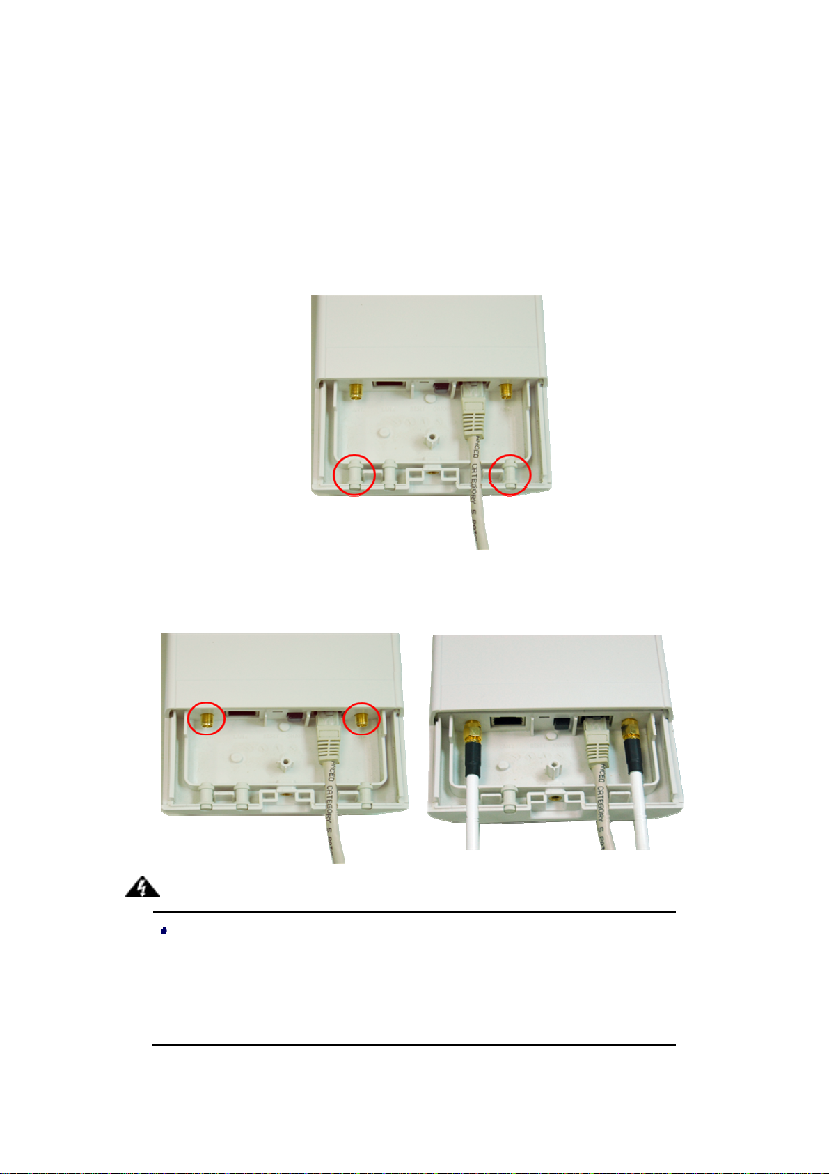
This chapter describes safety precautions and product information you have to know and
check before installing the CDS-5IP.
Preparation before Installation
Professional Installation Required
Please seek assistance from a professional installer who is well trained in the RF installation
and knowledgeable in the local regulations.
Safety Precautions
1. To keep you safe and install the hardware properly, please read and follow these safety
precautions.
2. If you are installing the CDS-5IP - Wireless External Unit for the first time, for your
safety as well as others’, please seek assistance from a professional installer who has
received safety training on the hazards involved.
3. Keep safety as well as performance in mind when selecting your installation site,
especially where there are electric power and phone lines.
4. When installing the CDS-5IP, please note the following things:
♦
Do not use a metal ladder;
♦
Do not work on a wet or windy day;
♦
Wear shoes with rubber soles and heels, rubber gloves, long sleeved shirt or
jacket.
5. When the system is operational, avoid standing directly in front of it. Strong RF fields are
present when the transmitter is on.

Page 6
Installation Precautions
To keep the CDS-5IP - Wireless External Unit well while you are installing it, please read and
follow these installation precautions.
1. Users MUST use a proper and well-installed grounding and surge arrestor with the
Wireless External Video Unit; otherwise, a random lightening could easily cause fatal
damage to the unit. EMD (Lightning) DAMAGE IS NOT COVERED UNDER
WARRNTY.
2. Users MUST use the “Power cord & POE Injector” shipped in the box with the CDS-5IP.
Use of other options will likely cause damage to the unit.
3. Users MUST power off the CDS-5IP - Wireless External Video Unit first before
connecting the external antenna to it. Do not switch from built-in antenna to the external
antenna from WEB management without physically attaching the external antenna onto
unit; otherwise, damage might be caused to the unit itself.

Page 7
Chapter 3 System Installation
Connect up
1. The bottom of CDS-5IP - Wireless External Video Unit is a movable cover. Loosen the
screw with a Philips screwdriver. Grab the cover and pull it back harder to take it out as
the figure shown below.
Figure 1 Move the Cover
2. Plug a standard Ethernet cable into the RJ45 port labeled “LAN 1”. Do not plug the cable into
the RJ45 port labeled “LAN 2”.
Figure 2 Cable Connection

Page 8
The secondary Ethernet port (labeled LAN 2) is for IP camera or next CDS-5IP Unit
video integration. To use it you need to enable the secondary port in advance before
connecting with the IP camera from the CDS-5IP`s Web Management as shown below.
3. Take out the power cord and POE injector from the gift box, and plug the power cord into the
DC port of the POE injector as the below picture shows.
Figure 3 Connect to POE Injector
4. Put what in the Step.2 and Step.3 together by plugging the other side of the Ethernet cable in
into the POE port of the POE injector When you finish the Step.4, the set will be like the
following picture:

Page 9
Figure 4 Plug the Ethernet cable to the RJ-45 jack of the injector
5. Press the black PWR button beside the LAN 1 Ethernet port.
6. Attach and fasten the removable cover to the bottom of the unit with the screw.
7. Power on the CDS-5IP - Wireless External Video Unit by plugging the power adapter to
the power socket.

Page 10
Using the External Antenna
The CDS-5IP - Wireless External Video Unit provides two reverse SMA antenna connectors
if you prefer to use the external antenna for your application instead of the built-in directional
antenna, please follow the steps below.
1. Remove the two plugs as circled below:
2. Connect your external antenna to the SMA-type connectors at the bottom of the Wireless
External Video Unit.
Users MUST power off the CDS-5IP - Wireless External Video Unit first before
connecting the external antenna to it. Do not switch from built-in antenna to the external
antenna from WEB management without physically attaching the external antenna onto
the unit; otherwise, damage might be caused to the unit itself.
Follow the steps described in Connect Up to finish the installation.
Warning:

Page 11
Pole Mounting
1. Turn the Wireless External Video Unit over. Put the pole mounting rings through the
middle hole of it. Note that you should unlock the pole mounting ring with a screw driver
before putting it through the CDS-5IP as the following right picture shows.
Figure 5 Pole Mounting – Step 1
2. Mount the CDS-5IP - Wireless External Video Unit steadily to the pole by locking the
pole mounting ring tightly. The mounting ring supports pole diameter 32mm to 70mm.
3. Now you have completed the hardware installation of the CDS-5IP - Wireless External Video
Unit .

Page 12
Chapter 4 Configuration
Connect the CDS-5IPwith your PC by an Ethernet cable plugging in LAN port of POE injector
in one side and in LAN port of PC in the other side. Power on the CDS-5IP by POE from the
supplied POE injector and press the black power button beside the LAN1 port.
1. Assign a static IP address to your PC which should be in the same network segment with
the CDS-5IP. As the default IP address of the CDS-5IP is 192.168.1.1, you may choose
from 192.168.1.2 to 192.168.1.254. Then click OK.
2. Open the web browser on your PC, key in the IP address (192.168.1.1) of the CDS-5IP in
the address bar, and then press Enter.

Page 13
3. Now, you will see the log-in page of the CDS-5IP. The default Name and Password are
“camsat” and “camsat” respectively. Enter the password and then click Login.
We’ll elaborate the CDS-5IP - Wireless External Video Unit factory default settings. You can
re-acquire these parameters by default. If necessary, please refer to the “Restore Factory
Default Settings”.
Table 1 Factory Default Settings
Features Factory Default Settings
Username camsat
Password camsat
Wireless Unit Name CDS-5IP
Operating Mode Video Bridge
Data Rate Auto
LAN
IPAddress 192.168.1.1
Subnet Mask 255.255.255.0
Gateway 0.0.0.0
Primary DNS Server 0.0.0.0
Secondary DNS Server 0.0.0.0
Spanning Tree Enable
802.11 Mode 802.11a/n
Country/Region European Union
Channel Number 5500 MHz (CH100)
SSID CAMSAT
Broadcast SSID Enable

Page 14
HT Protect Disable
Data Rate Auto
Output Power Full
Channel Mode 20MHz
WMM Enabled
RTS Threshold (byte) 2346
Fragmentation Length (byte) 2346
Beacon Interval 100
DTIM Interval 1
Space in Meter 0
Flow Control by AP Disable
Security Open System
Encryption None
Wireless Separation Disable
Access Control Disable
For users who use the CDS-5IP - Wireless External Video Unit for the first time, it is
recommended that you begin configuration from “Basic Settings” in “System” shown below:

Page 15
TCP/IP Settings
Open “TCP/IP Settings” in “System” as below to configure the parameters for LAN which
connects to the LAN port of the CDS-5IP. In this page, users may change the settings for
IPAddress, Subnet Mask, and DHCP Server.
Figure 6 TCP/IP Settings (Bridge)
Obtain IP Address Automatically: If a DHCP server exists in your network, you can
check this option, thus the CDS-5IP - Wireless External Video Unit is able to obtain IP
settings automatically from that DHCP server.
Since the CDS-5IP covers “Video Bridge mode”, “Master mode” as well as “Slave mode”, the
following steps are categorized for convenience reading to describe how to set each mode
after successful log-in.

Page 16
Video Bridge Mode
1. Open “Basic Settings” in “Wireless”. From Wireless Mode, select “Video Bridge” and
click “Apply” to save settings.
2. Go to “WDS Settings ” in “Wireless”, input the MAC address of the remote bridge to
“Remote AP MAC Address 1” field and click “Apply”;

Page 17
Bridge
uses the WDS protocol that is not defined as the standard thus compatibility
issues between equipment from different vendors may arise. Moreover, Tree or
Star shape network topology should be used in all WDS use-cases (i.e. if MASTER
2 and MASTER3 are specified as the WDS peers of MASTER1, MASTER2 should
not be specified as the WDS peer of MASTER3 and MASTER3 should not be
specified as the WDS peer of MASTER2 in any case). Mesh and Ring network
topologies are not supported by WDS and should be avoided in all the use cases.
3. Repeat the above procedures to configure the remote CDS-5IP.
4. Use ping to check whether the link between the two bridges is OK.
5. To get a better wireless connectivity, antenna alignment is strongly recommended after
both bridges are installed long distance apart.
6. Open “Antenna Alignment” in Tools. Choose the remote peer and click on the “Start”
button.
Note:

Page 18
7. Wait about 5 seconds, the antenna alignment starts and performs alignment every one
second.
8. Fix the local antenna and adjust the remote antenna elevation and horizontal direction.
During the adjustment, observe “Current RSSI” and “Signal Strength” in local bridge.
The value will refresh every 1 second. Fix the remote antenna when it reaches your
expectation. Usually, RSSI between -50 to -70dBm indicates rather good signal strength.
9. Adjust the local antenna after fixing the remote one. During the adjustment, observe
“Current RSSI” and “Signal Strength” in the remote bridge. Fix the local antenna when it
reaches your expectation. Under MASTER/SLAVE mode where Antenna Alignment Tool
is not available, another option is provided to check the signal strength towards the
connecting MASTER/SLAVE. Open “Connections” in “Status” as below, and click
“Refresh” to view the current signal strength of wireless connectivity. If the signal is not
so good, align the antenna manually.

Page 19
Master Mode
1. Choose Wireless > Basic Settings. Then you will see the “Basic Settings” page. Here,
you can set the parameters to optimize your application. Click “Apply”to save the
parameters. In addition, for better coverage of the Master, you may also use external
MIMO antennas; if so, remember to set the antenna setting from “Internal (16 dBi)” to
“SMA Connector” after your external antennas are physically installed.
Warning: Do not switch from built-in antenna to the external antenna from WEB
management without physically attaching the external antenna onto the CDS-5IP;
otherwise, damage might be caused to the device itself.

Page 20
2. If security is required, open Wireless > Profile Setting and enter “VAP Profile 1
Settings” as below. You may set the parameters like “Network Authentication” and “Data
Encryption” for more secure network communication in your application. Click Apply to
save the parameters.
Slave Mode
1. Choose Wireless > Basic Settings. Then you will see the “Basic Settings” page.
Choose “SLAVE” from Wireless Mode, and click “Apply” to save it. Feel free to change
the other parameters to optimize your application before clicking “Apply”.
Note: For longer transmission of the CDS-5IP, you may also use an external antenna; if
so, remember to set the antenna setting from “Internal (16 dBi)” to “SMAConnector” after
your external antenna is successfully installed.
Warning: Do not switch from built-in antenna to the external antenna from WEB
management without physically attaching the external antenna onto the CDS-5IP;
otherwise, damage might be caused to the device itself.
Table of contents
Popular Industrial Equipment manuals by other brands

ABB
ABB HT610930 Operation manual

INOXPA
INOXPA MCR Ex Installation, service and maintenance instructions

SCHUNK
SCHUNK AGE-XY Series Assembly and operating manual

ABB
ABB HT597151 Operation manual

Carlisle Fluid Technologies
Carlisle Fluid Technologies Ransburg IntelliFlow RM2 manual

Magnum Industrial
Magnum Industrial MI-93850 manual