12 13
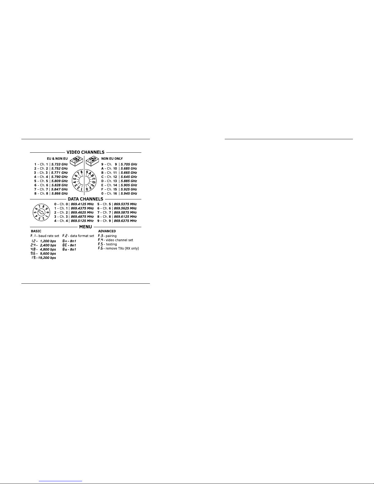
Setting the video operating channel remotely
In order to set the video transmission operating channel (for a specic
transmitter) remotely from the CAM-9 M Rx receiver level,
do the following:
1. Select the option from the main menu.
2. Select the identication number of the transmitter whose video
transmission operating channel you intend to change with the ENTER
button [I] and then conrm the selection by holding the SET button [H].
3. The receiver will communicate with the transmitter and the video
transmission operating channel currently set in the transmitter will
appear on the display.
4. Select the desired operating channel with the ENTER button [I] and then
conrm it with the SET button [H].
5. If the selected operating channel appears on the display [B] blinking,
then it has been congured properly. If the , symbol appears instead,
it indicates a transmission error (repeat steps from 1 to 4)
6. The device will return to the main menu.
Setting the data transmission parameters remotely
In order to set the data transmission parameters (data rate and format)
remotely from the CAM-9 M Rx receiver level, follow the instructions
in the [Method for setting the transmission rate and data format]
section at page 10. When the radio link parameters are being set, the
receiver, if its memory contains transmitters assigned to it, automatically
communicates with the transmitters and the entire network is congured
according to the CAM-9 M/S Rx receiver parameters.
Advanced settings
Testing the data link
In order to test the correctness of data transmission between the CAM-
9 M Rx receiver and the CAM-9 transmitters, select the option from
the main menu. The procedure will commence automatically. Testing can
be conducted both from the receiver and transmitters levels.
When the testing is completed, the result will appear on the display. The
display method depends on whether the testing was conducted from the
transmitter or receiver level.
Testing from the CAM-9 Tx transmitter level
- If, after testing is completed, the display alternates between (OK)
and the transmitter’s ID number, it indicates a correct transmission.
- If , appears on the display, it indicates a transmission error (check
the connections and test again).
Testing from the CAM-9 M Rx receiver level
- If, after testing is completed, the display alternates between (OK)
and the number of transmitters entered into memory, it indicates
a correct transmission.
- If the display alternates between and a number, it indicates
a transmission error between the receiver and the transmitter with
this ID number.
Removing a transmitter from the CAM-9 Rx receiver memory
- If there is a need to turn one of the transmitters o permanently
(removal, damage), it should be deleted from the CAM-9 M Rx
receiver memory. In order to do this, select the option from the
main menu in the receiver.
- Next, select the ID number of the transmitter to be deleted with the
ENTER button [I] and conrm the selection by holding the SET button
[H]. The transmitter will be deleted from the device memory and will
no longer be visible during testing, setting parameters, etc.
Restoring the device to default settings
- In order to reset the transmitter or receiver to the default settings,
disconnect the device’s power supply, press the ENTER button and
connect the power supply again.
- The display will count from 5 to 1, the ENTER button should be
held during that entire time. The device will reset itself to the
default settings.