Chiayo SDR-8200 User manual

Printed in Taiwan, Jan. 2008 12I1130
GREEN PRODUCT
SDR-8200 / SDR-7200
UHF PLL-Synthesized Dual / Single Channel
True Diversity Wireless Microphone System
SQ-7100 / SQ-6100 / SM-7100
OPERATION MANUAL

Thank you for choosing Chiayo wireless microphone system !
Our products are designed to last and for user friendly operation. Each system consists of :
- a receiver,
- a handheld or bodypack transmitter and,
- comes completely with all necessary accessories.
Each system has 100 factory preprogrammed frequencies and is ready for immediate use
after switch-on. However, all frequency settings can be changed to suit your individual needs,
if required.
There are two types of transmitter versions :
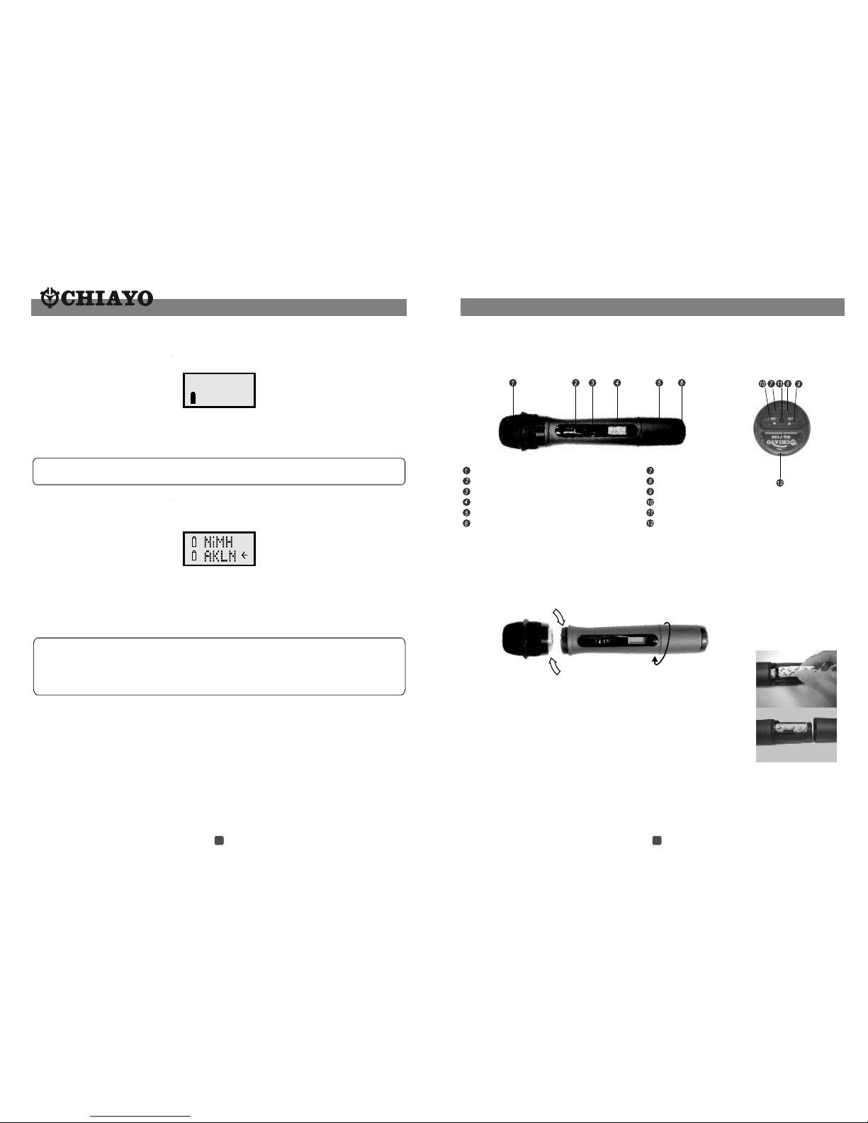
The Handheld transmitter is a complete wireless microphone by itself. It can only accept
dynamic or condenser microphone capsule modules specially designed by Chiayo.
The Beltpack transmitter can accept a wide range of inputs including Uni- and Omni-
directional lavalier microphone, headset microphone, guitar / instrument input or other line
input audio sources.
For more details, please take a few moments to read this operating manual to have a
thorough understanding of the function and operation of both transmitter and receiver.
With the introduction of this series, Chiayo offers musicians, PA and sound professionals a
high-quality and reliable state-of-the-art RF transmission link between transmitters and
receivers. Followings are brief description of various technologies used and features available
in these systems.
Tips to obtain the best results for a wireless microphone system
1. For transmitter, please use only fresh alkaline battery. Do not use general purpose
(carbon zinc) battery.
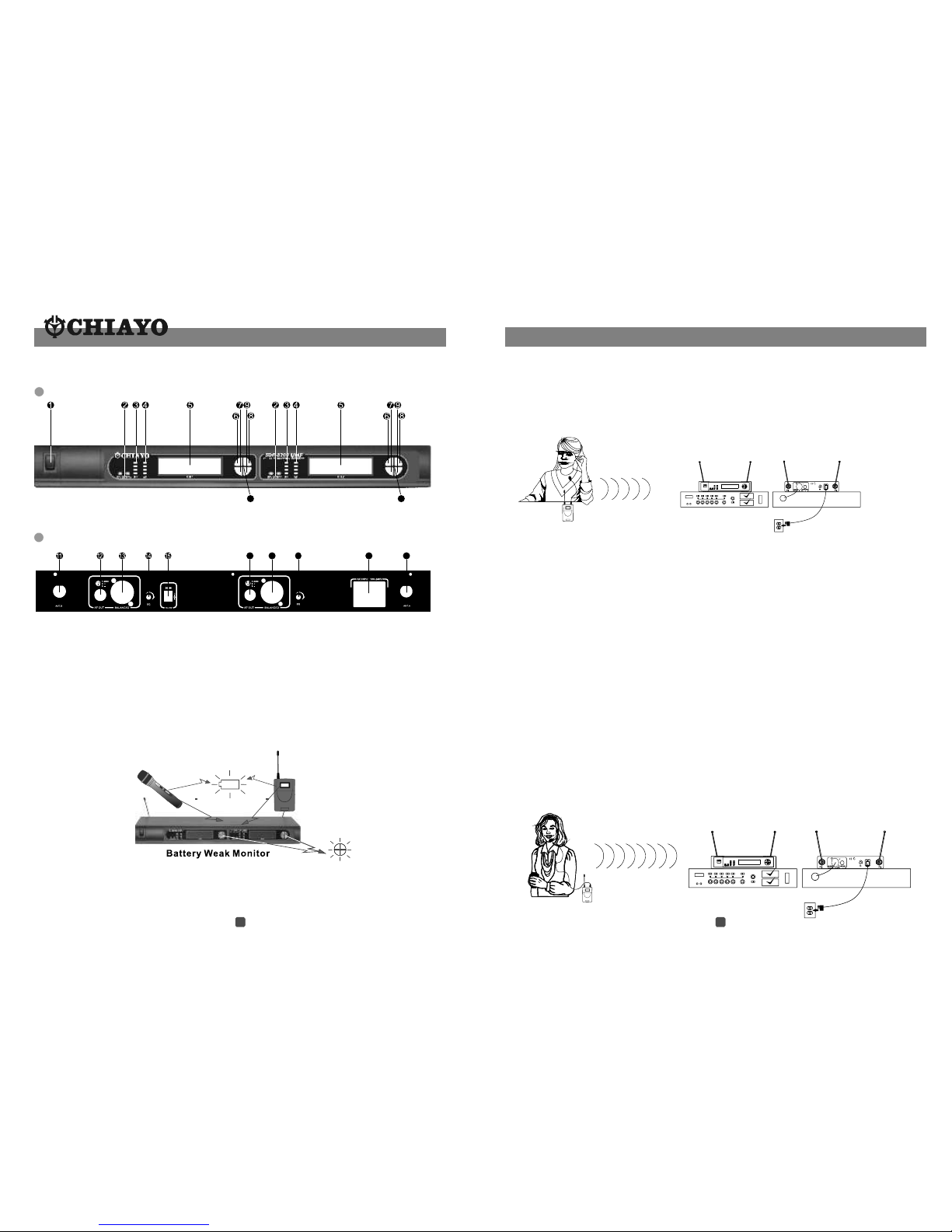
2. Transmitter and receiver should be as close as possible, but not less than 1m.
3. Position the receiver so that it has the least possible obstruction between it and the
transmitter. Line of sight is best.
4. If external antenna is used, low loss RF shielded cable should be used and the length of
the cable should not exceed 3m.
5. The receiver antenna should be kept as far away as possible from any metal surface.
6. A receiver can not receive signals from two transmitters at the same time.
7. Turn off the transmitter when not in use. Remove the battery if the transmitter is not to be
used for a period of time.
8.If the volume Control of the receiver is set too high, it may over-drive the input of the mixer,
causing distortion. Conversely, if the receiver output is set too low, the overall signal to
noise ratio of the system may be reduced. Adjust the output level of the receiver such that
highest sound pressure level going into the microphone causes no input overload in the
mixer, and yet permits the mixer level controls to operate in their normal range (not too
high or too low). This provides the optimum signal to noise for the entire system.
Simple DIY trouble shooting:
Case study 1: Transmitter is on, Receiver is on, but no RF signal received.
1-1. Transmitter and Receiver are having different frequencies . If this is the case, please
change either Transmitter and Receiver to the correct frequency or frequency group. For
PLL series, if the frequency group is correct, the channel could be wrongly selected on
either side. Please verify and select to the correct channel.
1-2 Transmitter is faulty
When step 1 is verified to be correct, then either Transmitter or Receiver is faulty. To prove
this transmitter is faulty, please use another functional transmitter (if any) of the same
model and same frequency to switch on the receiver, If this transmitter of the same frequency
could trigger on the receiver , then this proves that the other transmitter is faulty. Send it
back to Chiayo's authorized agent for service.
1-3 Receiver is faulty
When steps 1 & 2 failed to bring any result, then the receiver could be faulty. To verify,
please use another functional receiver (if any) of the same model and same frequency to
double check and send it back to Chiayo's authorized agent for service.
Case study 2: Transmitter could not be switched on.
2-1 Battery is weak or wrongly installed. If it is not the case, please check according to 1-2
above .
Case study 3: Strong interference signal received.
3-1 If interference could not be solved by adjusting the squelch (SQ) control to maximum,
please stop using this particular frequency (for a crystal locked system) and change to
another set of a different frequency. For a PLL system, please switch over to another
interference free channel.
Important Remarks !
Never attempt to open the electronic devices by yourself ! This must only be done by
authorized personnel and is all the more important for units connected to AC outlets.
If devices are opened by customers in breach of this remark, the warranty will be null
and void.
Always disconnect the devices from the AC mains by removing the plug when you wish
to change connections or move the devices to a different place.
Keep the devices away from central heating radiators and electric heaters.
Never expose them to direct sunlight.
Use the devices in dry rooms only.
Use a damp cloth for cleaning the devices. Do not use any cleansing agents or solvents.
1 14

Operating the Guitar System
1.Refer to Fig.6 below, connect the AC power adaptor to the DC IN connector on the back
of the receiver. Plug the adaptor into an AC wall socket. Push to switch on the receiver.
The LCD on the receiver will glow.
2.Raise the antennas and point away from each other at a 45 angle from the vertical to
achieve optimum reception.
3.Connect the receiver's Unbalanced 1/4" PHONE JACK AUDIO OUT connector to the
amplifier input, using a standard guitar cable.
4.Connect a Guitar cable to your Guitar and Adjust the volume control of your Guitar to
desired level in order to match wireless output to that of a wired system.
5.Plug the other end of the Guitar cable to the beltpack transmitter's input connector. Press
the power on / off switch to switch on the transmitter. The transmitter's red LED will flash
and the receiver's red DIVERSITY A/B lights will glow.
6.Slide the transmitter's AUDIO ON / OFF switch to ON position.
7.Play your Guitar. Proper operation is indicated by :
Steady glow of the receiver's DIVERSITY A / B lights and RF indicator.
flickering of the receiver's AF indicator lights when the audio goes into the mike.
8. During the pause of the presentation, slide the Audio ON / OFF switch to OFF
position.
9.When the performance is over, turn off the amplifier and turn off the transmitter power.
O
3
121.GND
2.
3.+
-
Fig.6
1.GND
2.
3. +
-
3
12
16
10
1.Power switch
2.Diversity AB indicator
3.RF indicator
4.AF indicator
5.LCD
6.UP button
7.DOWN button
8.MENU
9.SET
10.Mic-ba ttery weak indicator
11.Antenna B (TNC so ck et)
12.Unbalanced AF out
13.Balanced AF out
14.Squelch control
15.DC in
16.Antenna A(TNC socket)
SDR-7200
Models
Frequency Band
No.of Ch annel
No.of Re ceiver
Display
Rack size
Power supply
Rack mount oiece
Handheld Transmitter
Bodypack Transmitter
Battery used
Receiving mode
SDR-8200
UHF
100
12
TRUE DIVERSITY
WHITE IN BLUE LCD
1/2 19" RACK 19" RACK
12V / 800 mA AC adapto r
SQ-6100 SQ-7100
SM-7100
AA * 2 pcs ( Alkaline recommended )
MP-50 ( optional ) -
12V / 800 mA AC adaptor or switching power
Parts and functions of SDR-7200 receiver
Front
Rear
13 2

3
121.GND
2.
3.+
-
O
6. Slide the transmitter's AUDIO ON / OFF switch to ON position.
7. Speak in the normal conversational voice. Proper operation is indicated by :
Steady glow of the receiver's DIVERSITY A / B lights and RF indicator.
Flickering of the receiver's AF indicator light when you speak into the mike.
8. During the pause of presentation, slide the Audio ON / OFF switch to OFF position.
9. When the presentation is over, turn off the sound system and turn off the transmitter power.
Operating the Headset System
1.Refer to Fig.5 below, insert the cable into the cable restraint, connect the AC power adaptor
to the DC IN connector on the back of the receiver. Plug the adaptor into an AC wall socket.
Push to switch on the receiver. The LCD on the receiver will glow.
2.Raise the antennas and point away from each other at a 45 angle from vertical to achieve
optimum reception.
3.Connect the receiver's Balanced or Unbalanced AUDIO OUT connector to the mixer input
using an XLR to XLR audio cable or 1/4" to 1/4" phone plug cable. Set the receiver's output to
match the sound system's input.
4.Adjust headband and place the headset on head, and keep it approximately 1/2" from side
of the mouth.
5.Plug the connector ( mini XLR or phone plug ) of the headset microphone into the beltpack
transmitter connector input. Press the power on / off switch to switch on the transmitter. The
transmitter's red LED will flash and the receiver's red DIVERSITY A/B lights will glow.
6.Slide the transmitter's AUDIO ON / OFF switch to ON position.
7.Speak in normal conversational voice. Proper operation is indicated by :
Steady glow of the receiver's DIVERSITY A / B lights and RF indicator.
Flickering of the receiver's AF indicator light when you speak into the mike.
8.During the pause of the presentation, slide the Audio ON / OFF switch to OFF position.
9.When the presentation is over, turn off the sound system and turn off the transmitter power.
3
121.GND
2.
3.+
-
Fig.4
Fig.5
10
19
20
16
17
18
1. Power switch
2. Diversity A B
3. RF indicator
4. AF indicator
5. LCD
6. UP button
7. DOWN button
8. MENU
9. SET
10. Mic-battery weak indicator
11. Antenna B (TNC socket)
12. CH2 Unbalanced AF out
13. CH2 Balanced AF out
14. CH2 Squelch control
15. DC in
16. CH1 Unbalanced AF out
17. CH1 Balanced AF out
18. CH1 Squelch control
19. AC in
20. Antenna A ( TNC socket )
10
Front
Rear
Parts and functions of SDR-8200 receiver
312

3
121.GND
2.
3.+
-
Operating the Handheld Microphone System.
1. Refer to Fig.3.below, connect the AC power adaptor to the DC IN connector on the back
of the receiver. Plug the adaptor into an AC wall socket. Push to switch on the receiver
power on / off switch. The display LCD on the receiver will glow.
2.Raise the antennas and point away from each other at a 45 angle from vertical to
achieve optimum reception.
3.Connect the receiver's Balanced or Unbalanced AUDIO OUT connector to the mixer
input using an XLR to XLR audio cable or 1/4" to 1/4" phone plug cable. Select the
receiver's output to match the sound system's input.
4.Press the transmitter's PWR ON / OFF to switch ON the transmitter. The transmitter's
red LED will give a flash to indicate the battery power is ok. If the Red LED stays constant
glow, it indicates battery is weak and a change of battery is necessary. The receiver's
Diversity A / B and RF indicator will glow to indicate RF signals have been received.
5. Talk or sing into the microphone. Normal operation is indicated by :
Steady glow of the receiver's DIVERSITY A / B lights and RF indicator.
Flickering of the receiver's AF indicator light when you speak into the mike.
6.When the performance is over, turn off the sound system and press the PWR switch to
OFF the handheld microphone.
°
Operating the Lavalier System
1.Refer to Fig.4.Below, connect the AC power adaptor to the DC IN connector on the back
of the receiver. Plug the adaptor into an AC wall socket. Push to switch on the receiver.
The LCD on the receiver will glow.
2.Raise the antennas and point away from each other at a 45 angle from vertical to
achieve optimum reception.
3.Connect the receiver's Balanced or Unbalanced AUDIO OUT connector to the mixer input
using an XLR to XLR audio cable or 1/4" to 1/4" phone plug cable.
Set the receiver's output to match the sound system's input.
4.Press the lavalier microphone into the mounting clip and attach it to your garment.
Do not cover the microphone with your clothing, and keep it approximately 8 to 12 inches
below your chin.
5.Plug the connector ( mini XLR or phone plug ) of the lavalier microphone into the
beltpack transmitter connector input. Press the power on / off switch to switch on the
transmitter. The transmitter's red LED will flash and the receiver's RF LED bar will glow to
indicate that signals have been received.
°
Fig.3
Making changes to various settings in SDR-7200 / SDR-8200
1. Make changes to CHANNEL / FREQUENCY
This can only be done at the Main page display.
Press SET for about 3 seconds, the cursor at channel number will flash to allow
a change. Press + ( UP ) to increase the channel number ( from 0 to 100 ) and
press - ( DOWN ) to decrease the channel number. As the channel changes, the
corresponding frequency will also be changed !
After selecting the desired channel ( frequency ), idle it for about 5 seconds and
the setting will be automatically saved into the memory.
CHANNEL: 001
FREQ: 700.000MHZ
4. AUTO SCAN function
Press MENU button until the AUTO SCANNING page appear.
Press SET for about 3 seconds to start the auto scan function. The receiver will scan
out the next cleaner channel. It takes a couple of minutes to perform the scan
function. After the next cleaner channel(frequency) has been selected, idle it for
about 5 seconds and the setting will be automatically saved into the memory.
AUTO SCANNING
CHANNEL : 001
SQUELCH SETUP
LEVEL:01
3. Make changes to SQUELCH LEVEL
Press MENU until this page appears.
Press SET for approx. 3 seconds to enter the set mode and the cursor will flash to
allow changes. Press UP to increase the Squelch level ( from 01 to 10 ) and press
DOWN to decrease the squelch level
After selecting the desired squelch level, idle it for about 5 seconds and the setting
will be automatically saved into the memory.
2. Make changes to VOLUME
Volume setting can be made at any page display by pressing the UP and DOWN
buttons. (The changes will not be saved and stored in memory!)
VOLUME : 14
MIN MAX
11 4

Operation
Chiayo Transmitters and Receivers have factory preset to allow immediate usage after
switch-on.
However, please note that the transmitter Sensitivity function is dependent on application
such as close proximity singing or tripod mouth speech. To avoid overmodulation and
distortion, please check whether the preset sensitivity level is suitable for your particular
application. For close proximity singing purposes, please select lowest sensitivity level
whereas for tripod mount speech purposes, please select a higher sensitivity level.
If you have made changes to the setting, after making proper selection on Transmitter and
Receiver settings the system is ready for operation. However, both antennas of the receiver
must be installed to assure a good reception.
First switch on the receiver by pressing the Power On / Off switch. The LCD display will show
the information last stored.
Switch on the matching transmitter with the correct matching frequency. The LCD display will
show the information last stored.
The LED RF indicator on the receiver front panel will light up indicating RF signal has been
received. If this is not the case, please check and verify the frequency setting on both
transmitter and receiver. When transmitter is moving around, the Diversity A B switch will light
on alternately to indicate the stronger reception on either A or B antenna.
When voice is spoken into the microphone, the LED AF indicator on the receiver front panel
will light on and flashes according to the intensity of the AF signal.
There are two different audio outputs at the rear side of the receiver: Balanced ( Microphone
level ) and Unbalanced ( LINE level ). Please select the matching output to match the input of
the connecting Mixer or Amplifier.
RACK MOUNTING
SDR-7200 are 1/2 19" casing and
specially designed (optional) 19" rack
mount adapters (MP-50) are available
for your installation purposes.
Installation instructions are as Fig.2.
RECEIVER INSTALLATION
For best operation, the receiver should be at
least 1m above the ground and at least 1m
away from a wall or metal surface to minimize
reflections. The transmitter should also be at
least 1m away from a wall or metal surface to
minimize reflections. The transmitter should
also be at least 1m away from the receiver, as
shown in Fig.1.
Keep antennas away from noise source such
as motors, automobiles, neon light as well as
large metal objects.
Fig.1
Fig.2
510

9
Making changes to various settings in SM-7100
3.Input Level Gain Control Adjustment
Low impedance (Lo-Z) " MT" & high impedance (Hi-Z) " GT" gain controls are
situated inside the transmitter. Gain controls are adjustment ports that enable you to
use microphones of differing output levels and Guitar or instruments with Hi-Z
output. To adjust microphone (Lo-Z) input levels, turn the "MT" control and to adjust
the Guitar or instrument (Hi-Z) input, adjust the "GT" gain control to set the
transmitter's desired audio input level.
1.Making changes to CHANNEL / FREQUENCY:
Use UP or DOWN button to go to the CHANNEL /FREQUENCY page.
The cursor will flash to allow changes to be made. Pressing UP or DOWN button
will increase or decrease the channel number. The corresponding frequency will
change accordingly. When a desired channel(frequency) is being selected, it will
be automatically saved and stored in the memory.
Remark : When changing transmitter frequencies, user should take care
not to cause interference to other channels / users.
2.Making changes to Battery selection:
Use UP or DOWN button to go to the Battery selection page.
Press SET for about 2 seconds to activate the cursor. Press UP or DOWN button to
move the cursor to either NiMH ( rechargeable battery ) or AKLN ( Alkaline battery )
position.
When the desired option has been selected, press SET for about 2 seconds to save
and store the data in the memory.
Remark : "NiMH" must be selected when rechargeable battery is being
used. Never select "AKLN" ( Alkaline ) when transmitter is intended for
charging as Alkaline battery can not be charged ! Wrong selection of
battery will cause battery sensing electronics to display wrong information
and mislead charging status.
CH: 086
746.250
Microphone capsule module
Battery status LED
Audio mute switch
LCD
Battery compartment
Rotating protective cap for controls
(also serves as color identification cap)
Power on/off
Set
Up
Down
Charging port
Name plate
Changing the capsule
First unscrew the metal grill from the housing, take out the capsule and then replace it with
a new one. Either dynamic or condenser type can be chosen to fit your requirement for any
application.
Caution
Many batteries are known to have leakage problem of conductive and corrosive liquid.
Please remove the batteries if they are not to be used for a long period.
Due to various unstandardized sizes ( diameters ) of " AA " batteries, this battery
compartment is designed to accommodate the most commom Alkaline batteries only.
UHF Handheld Transmitter SQ-7100
Parts and functions
Battery Installation
SQ-7100 microphone requires 2 pieces of " AA " size batteries
to operate. Please insert the batteries according to the correct
polarity as indicated.
9 6

GAIN setting (GT/MT)
Gain control is an adjustable design that enables user to set different output levels. GT is for
the use of instrument with high impedance, such as guitar while MT is for the use of low
impedance such as lavalier or headset microphone.
10
11
Antenna
Battery weak indicator
Audio mute switch
Mini-XLR connector
Power ON / OFF switch
LCD display
Charging port
Cover release button
Charging contacts
Lavalier microphone
Mic clip
12
13 14
1615
14
13
12 SET
UP
DOWN
GT
MT
15
16
Making changes to various settings in SQ-7100
3. Making changes to Sensitivity Level:
Use UP or DOWN button to go to the SENS SET page.
Press UP or DOWN button to increase or decrease the Sensitivity Level of the transmitter.
The MAX level is 4 and the MIN level is 1.
When a desired sensitivity level has been selected for your application, it will be
automatically saved and stored in the Memory.
Remark : When selecting Sensitivity level, please keep in mind that Level 1 is for
close proximity singing purposes whereas Level 4 is for use of transmitter on
tripod mount for speech purposes. When Level 4 setting is used for close
proximity singing, high SPL input will result in undesirable distortion in the
output.
After performing setting changes, you could turn the protective cover 180° in either
direction to block the buttons from being accidentally adjusted.
2. Making changes to Battery selection:
Use UP or DOWN button to go to the Battery selection page.
Press UP or DOWN button to move the cursor to either NiMH ( rechargeable battery ) or
AKLN ( Alkaline battery ) position.
When the desired battery has been selected, it will be automatically saved and stored in the
memory.
Remark : "NiMH" must be selected when rechargeable battery is being
used. Never select "AKLN" ( Alkaline ) when transmitter is intended for
charging as Alkaline battery can not be charged ! Wrong selection of
battery will cause battery sensing electronics to display wrong information
and mislead charging status.
1.Making changes to Channel:
Use UP or DOWN button to go to the CHANNEL/ FREQUENCY page.
The cursor will flash to allow changes to be made. Pressing UP or DOWN button will increase
or decrease the channel number. The corresponding frequency will change accordingly.
When a desired channel is selected, it will be automatically saved and stored in the memory.
CH: 086
746.250
78
8
9
11
This manual suits for next models
1
Other Chiayo Microphone System manuals

Chiayo
Chiayo R-1001 User manual

Chiayo
Chiayo RRS-2000 User manual

Chiayo
Chiayo SDR-6200 IrDA User manual

Chiayo
Chiayo Smart 300 User manual

Chiayo
Chiayo AIR-812 User manual

Chiayo
Chiayo Live-100 series User manual

Chiayo
Chiayo Q-200 User manual

Chiayo
Chiayo R-1010 User manual

Chiayo
Chiayo Stage-100 Series User manual

Chiayo
Chiayo QR-4000N User manual

Chiayo
Chiayo IWR-320 User manual

Chiayo
Chiayo QR-4000 U User manual

Chiayo
Chiayo QR-2000N User manual

Chiayo
Chiayo DWR-5420 User manual

Chiayo
Chiayo R-1001 User manual

Chiayo
Chiayo SDR-5100 IrDA User manual

Chiayo
Chiayo IRX2 User manual

Chiayo
Chiayo Artist User manual

Chiayo
Chiayo SQ-6100 IrDAR User manual

Chiayo
Chiayo IWM-202 User manual