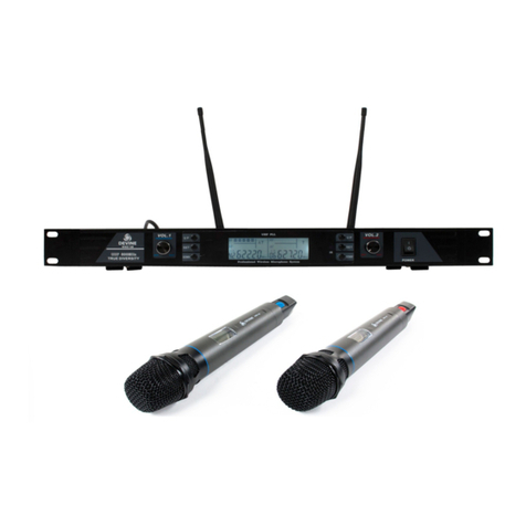
Devine WMD-IE User manual

WMD-IE
Wireless In-Ear Monitoring System
User Manual
The information included in this user manual is subject to change at any time and without notification:
Version: 1.0 Date and author initials: 04-08-2020 RV Revision date and author initials : -

Introduction
Thank you for purchasing the Devine WMD-IE in-ear monitoring system. Before unpacking the included
components, e recommend reading this user manual thoroughly to ensure that you are completely familiar
ith all of the functions this product has to offer. When unpacking the box, please make sure that all of the
components and accessories listed belo have been included. In the event that the product does not
function as it should, s itch off the po er and remove the po er cable from the mains po er socket before
contacting your local retailer for further advice.
Box contents:
– Devine WMD-IE base station (transmitter)
– Devine WMD-IE-BP bodypack (receiver)
– 6.35 mm TS jack audio cable
– set of in-ear headphones (test models)
– 2x AA batteries (for testing)
– 1x po er supply for WMD-IE base station
– 1x base station antenna
Inspection of the device and included accessories
In the event that the device or any of the included accessories have been damaged or rendered defective in
transit, please contact your local retailer for advice.
Please note: The products seen in the images included in this manual may differ slightly from the product
received.
ontact:
Devine Pro Audio Products
Verrijn Stuart eg 18
4462 GE Goes
The Netherlands
Please do not send any physical products to this correspondence address.
Should you wish to send a product or repairs or or a re und, please contact your retailer or an RMA request
(Return Merchandise Authorisation)
The information included in this user manual is subject to change at any time and without notification:
Version: 1.0 Date and author initials: 04-08-2020 RV Revision date and author initials : -

Safety Instructions
Every person involved ith the installation, operation and maintenance of this device must:
- Be qualified.
- Be skilled.
- Have read the instructions included in this user manual.
- Be sure that neither the device nor the included accessories are damaged. Should the device or the
included accessories be damaged, please contact your retailer for further advice.
- Ensure that the device is in good orking condition and is safe to operate. Please follo the advice and
instructions as they are described in this user manual.
Damage caused by misuse and/or modifications made to the device are not covered by the arranty.
This device does not contain any parts that can be repaired or replaced by the user. Should maintenance or
repairs be necessary, they must be carried out by a qualified technician.
Important information regarding health and safety:
- Do not remove any labels or stickers from this device.
- Do not leave any cables lying around here they are in danger of causing a tripping hazard.
- The housing of this device must not be opened and any hard are or soft are that may be present must not
be modified.
- For optimal performance, any inputs of the device should not be fed ith a signal higher than necessary.
- The device must only be used indoors; contact ith ater, rain and moisture must al ays be avoided. Do
not place any objects containing liquid on top of the device.
- Remove the device from any nearby flames or heat sources; do not place it near flammable fluids, gasses
or objects.
- Disconnect this device from a po er source if it is not being used for a long period of time, if maintenance is
necessary, or if it needs to be cleaned.
– Do not pull or tug on the cable to remove a plug as this may cause damage.
- Do not use any cables other than those specified in this manual. Do not use defective cables. Please
contact your retailer if the included or specified cables do not function properly ith this device.
- In the event that the device is exposed to extreme temperature changes (e.g. transported from a cold
outdoor environment into a arm indoor environment), it should not be turned on until it has reached room
temperature. This is necessary to prevent moisture (condensation) from forming inside the device, hich
may cause electric shocks.
Use & Operation Guidelines:
- This device is intended for indoor use and must only be operated by adults.
- This device is not suitable for use by children and must al ays be operated by an adult.
- This device can only be used in appropriate environments here no damage to the device can occur. Do
not use the device in moist or dusty environments such as:
- indoor s imming pools here chlorine is used
- beaches or any location here sand and/or salt is present
- outdoors
- in indoor spaces here intense heat sources are present, or here it can reach temperature levels
that ould be considered uncomfortable for a person.
- Avoid impact and collisions during use and transport. Do not move or transport the device hile it is in use.
Avoid using excessive force hen installing and operating the device.
- Any user must become familiar ith the functions of this device before using it.
- In case of emergency, any user must al ays be able to disconnect the device from the po er source.
Al ays ensure easy access to the po er supply at one of the follo ing points:
•the included po er supply
•the plug that’s connected to a po er socket
•an external po er block ith on/off s itch or dual-pole s itch able to cut the po er
The information included in this user manual is subject to change at any time and without notification:
Version: 1.0 Date and author initials: 04-08-2020 RV Revision date and author initials : -
WARNING!
Keep this device away from moisture, water and rain
to prevent any danger of electric shocks!

- Ensure that both the AC/DC po er supply and base station are provided ith enough ventilation space to
prevent overheating. At least 10 centimetres of space must be made around the AC/DC adapter to ensure
sufficient air circulation.
- Should the device not be used in the manner described in this user manual, damages or even injuries could
occur. Devine cannot be held responsible for any injuries or damages that occur as a result of improper use
of this product.
Storage & Transport:
- This product has been designed for mobile use and can be transported in its original packaging as long as
it is ell protected against shocks and impact. It is also possible to transport the device in an appropriate
case or flight case ith a lined, protective interior that provides a secure fit for all components so that they
are unable to shift in transit.
– This device has not been designed for continuous (24/7) use. Regularly s itching the device off ill not
effect the expected lifespan of the device.
– When the device is not in use for long periods of time, al ays disconnect the device from the mains po er
and store it in a dust free environment.
– Do not expose the device to extreme temperature shifts.
Housing:
- Frequently inspect the housing of the device and al ays just before use. Avoid operating the device if any
large dents or cracks are found in the housing, or if scre s are missing. Do not use the device if the housing
is not in good condition. Contact your local retailer or a qualified technician if you are unsure about the state
of the device.
- Check the device and scre s for any corrosion. If any corrosion is found, do not use the device. Contact
your dealer or a qualified technician if the scre s or housing sho any signs of corrosion.
- Ensure that every po er and signal socket is securely fitted. Do not use the device if any of the sockets are
not secure.
- Avoid the build up of any dust and dirt. Clean the device once a month by disconnecting it from the po er
supply and iping it do n ith a dry or slightly moist cloth. If the device is used frequently, the device should
also be cleaned more frequently.
Symbol Explanation:
Ensure that this device is disposed of properly. This product falls under the WEEE (Waste
Electrical and Electronic Equipment) directive. The requirements of this directive apply to all
manufacturers and producers of electronic devices in the EU. Do not thro this product a ay
ith normal refuse. Please contact your local authority for more information about ho to
recycle and dispose of these products in your region. By recycling this product in the proper
manner, e can ork together to ensure that e can continue to enjoy these kinds of
products and still protect the environment as much as possible.
E: The CE logo indicates that this product meets the European norms and requirements to
hich it must legally conform.
Suitable for indoor use only: This product as designed for indoor use only. The maximum
environmental temperature must not exceed 40 degrees Celsius (104 degrees Fahrenheit).
The information included in this user manual is subject to change at any time and without notification:
Version: 1.0 Date and author initials: 04-08-2020 RV Revision date and author initials : -

Battery safety:
WARNING!
- If the battery is replaced incorrectly, this may cause the battery to explode.
- Only replace a battery ith the same battery type.
- Never expose batteries to intense heat, including sunlight, open flames, etc.
- Never store batteries in a hot, high temperature environment. This may cause the battery to explode and/or
result in the leakage of flammable liquids or gasses.
- Never expose batteries to an open flame or place them in or near a hot oven.
- Never purposefully damage batteries or try to cut into them as this may cause the battery to explode.
- Do not expose batteries to extremely lo air pressures (at high altitudes) since this may cause the battery
to explode and/or result in the leakage of flammable liquids or gasses
- If the device is not in use for a long period of time (a fe months, for example), ensure that any batteries
are removed from the device before it is stored.
- Al ays remove empty batteries from the device immediately.
- Avoid carrying batteries in a pocket, allet, or bag. Contact ith metal objects like coins, keys and similar
can cause damage, leakages, or short-circuits.
- Al ays ensure that batteries are kept out of reach of children.
Recycling:
Never dispose o batteries with normal household waste. Batteries can contain substances that are
damaging to the environment. I a battery is recycled using the correct methods, it can be a valuable
source o reusable materials. Contact your local council or more in ormation about how best to
dispose o batteries.
The information included in this user manual is subject to change at any time and without notification:
Version: 1.0 Date and author initials: 04-08-2020 RV Revision date and author initials : -

The Legal Use of Wireless Systems
Please note: The legislation regarding the authorised use of ireless systems is different in different
countries. Al ays check ith your local council, governing body, or a specialist to be certain that a licence is
not required before you can use a ireless system.
Operating a ireless system using the incorrect frequencies can lead to malfunctions and affect the system
performance as ell as violate local la s and regulations regarding the use of ireless transmission
equipment.
---
The Devine WMD-IE system operates using the ‘duplex gap’ frequency range: 823 to 832 MHz.
This frequency band can be used freely in many EU countries. At the time of riting, a license is required to
use this frequency band in the follo ing countries:
AT: Austria
CY: Cyprus
FR: France (not for professional users)
HR: Croatia
IE: Ireland
LT: Lithuania
LV: Latvia
PL: Poland
SK: Slovakia
UK: United Kingdom
This device has a maximum transmission capacity of 100 mW hich may not be legally used in all EU
countries. At the time of riting, the follo ing countries enforce a legal limit on transmission capacity:
For frequencies 823 MHz – 826 MHz:
DE: Germany: max. 82 mW
FI: Finland: max. 12 mW
IT: Italy: max. 10 mW
LT: Lithuania: max. 50 mW
RO: Romania: max. 50 mW
SE: S eden: max. 10 mW
UK: United Kingdom: max. 50 mW
other EU countries: max. 20 mW
For frequencies 826 MHz – 832 MHz:
CZ: The Czech Republic: max. 50 mW
ES: Spain: max. 20 mW
FI: Finland: max. 12 mW
IT: Italy: max. 10 mW
LT: Lithuania: max. 50 mW
RO: Romania: max. 50 mW
SE: S eden: max. 50 mW
UK: The United Kingdom: max. 50 mW
Other EU countries: max. 100 mW (is the max. ERP of the Devine WMD-IE)
The information included in this user manual is subject to change at any time and without notification:
Version: 1.0 Date and author initials: 04-08-2020 RV Revision date and author initials : -

Please note that the legal use of a frequency band does not guarantee interference free performance. It is
al ays the case that any nearby equipment that uses the same or similar frequency can cause signal
interference.
The information included in the overvie above is correct at the time of riting. Due to the continuous
regulatory changes made by different countries as a result of constant ireless frequency range reforms, it
may be the case that the information included above is incorrect at the time of reading. Al ays consult your
local governing body to be certain of the most recent regulations regarding the use of ireless systems.
The information included in this user manual is subject to change at any time and without notification:
Version: 1.0 Date and author initials: 04-08-2020 RV Revision date and author initials : -

Overview & Use
Transmitter
1. ON/OFF s itch
2. DOWN button
3. Function button
4. UP button
5. IR synchronisation point
6. Display
7. Earphone volume control
8. Earphone monitoring output, 6.35 mm TRS jack
9. Input 1: 6.35 mm TS jack
10. Input 1 volume control
11. Antenna
12. MIX output for linking multiple systems or passing on monitor signal, 6.35 mm TS jack
13. Input 2 volume control
14. Input 2: 6.35 mm TS jack
15. Input 3: 6.35 mm TS jack
16. Input 3 volume control
17. Input 3 phantom po er (9 V DC), On/Off
18. DC po er input for included po er supply
Receiver
1. Antenna
2. ACT transmission strength
3. ACT receiver strength
4. ON/OFF s itch
5. Display
6. DOWN button
7. Function/Enter button
8. UP button
9. Battery compartment (2x AA)
10. Battery compartment cover
11. Volume control
12. Line output
13. Ear-phone output
The information included in this user manual is subject to change at any time and without notification:
Version: 1.0 Date and author initials: 04-08-2020 RV Revision date and author initials : -

Using The System
This ireless in-ear system includes a number of options and features. It is therefore essential that the
instructions and advice included belo are read and understood in detail to ensure that you can get the very
best out of the system hile using it safely.
Ensure Optimal Transmitter and Receiver Signal Strength
In areas here there is a large amount of ireless traffic (for example, in a street of pubs, restaurants, or
venues, all of hich may use ireless background music systems or live performance equipment), it is
al ays possible that other ireless traffic may affect the ireless performance of your system.
In the orst case, this can cause serious problems ith the performance of the WMD-IE in-ear monitoring
system.
To prevent or solve these possible problems, the follo ing measures can be taken:
– Make sure that any other transmitting or receiving device or equipment that operates using the same or
similar frequency band is moved at least 1 metre a ay from the system.
– As much as possible, try to maintain a clear ‘line of sight’ bet een the transmitter (base station) and
receiver (bodypack) and ensure that nothing is blocking signal transmission. Obstructions can include alls,
furniture, or audience members. The less the signal is blocked, the more stable the signal becomes.
– Place the transmitter in a relatively high position. This ill increase the ‘line of sight’ of the transmitter so
that the receiver can better detect the signal.
Switching the Base Station Transmitter On
Before s itching the base station transmitter on, ensure that it is placed in an optimum position (as described
above) and on a stable surface. Connect the DC po er supply to the po er input of the base station and
plug the po er supply into a compatible mains po er socket. Use the Po er button of the base station to
s itch it on and off.
onnecting the System to an Audio Installation
On its o n, this system is not able to produce sound. As such, the base station has been fitted ith audio
inputs so that it can be connected to an external audio system.
A standard external audio system usually includes a PA mixer or similar equipment able to output a separate
mixed audio signal to the in-ear system, so that the artist is provided ith a balanced mix of all the different
incoming audio signals. The WMD-IE transmitter provides three 6.35 mm TS jack inputs, each ith separate
volume controls and supports line-signals and microphone signals.
A mono signal is sent to the bodypack receiver and through both ear-phones. It is not possible to create a
precise stereo mix using this system.
It is also possible to monitor the signal being sent to the in-ear system from the front-of-house using the
6.35 mm TRS jack earphone monitoring output of the base station.
If in doubt, your local retailer shall be able to offer advice regarding the correct cabling. Usually, you ill only
need a 6.35 mm TS jack cable like the cable included. If other options are required, there are adapters and
adapter cables that can be purchased separately to solve any connection problems.
The information included in this user manual is subject to change at any time and without notification:
Version: 1.0 Date and author initials: 04-08-2020 RV Revision date and author initials : -

Display Symbol Explanation
The displays of both the transmitter and receiver use the follo ing terms and/or symbols:
Transmitter Meaning Receiver Meaning
Audio signal strength (more or
less bars are filled depending
on signal strength)
Signal level per antenna
Used antenna (the system
continuously s itches
bet een the antenna ith the
best reception, A or B)
SET mode:
GR: Available frequency
CH: channel selection
SCAN: Scan available
channels
HI: Hi / Lo strength selection
IR-synchronisation function
active
Audio signal strength (more
or less bars are filled
depending on signal
strength)
Opens adjustable functions Selected channel
Functions locked so they
cannot be adjusted
Selected frequency
Channel indication Infrared-synchronisation
mode
Mute function active Battery level status ith
voltage level
Transmission strength
High/Lo
Locked
Unlocked
Transmitter hannel Selection
S itch on the transmitter and press the SET button to activate channel selection mode. Use the UP and
DOWN buttons to change the channel.
Transmitter Frequency Selection
Press the SET button once more to activate the frequency selection mode. Use the UP and DOWN buttons
to change the frequency. The frequency is adjusted in 0.05 MHz steps.
Transmitter Frequency Selection (Larger Steps)
Press the SET button once more to activate the second frequency selection mode here the frequency can
be adjusted in larger steps. Use the UP and DOWN buttons to change the frequency. The frequency is no
adjusted in 1 MHz steps.
Power ontrol Mode
In Po er Control mode, the transmission strength can be changed to Hi or Lo. This is function has been
included to ensure that a stable signal can be achieved in any situation.
If there is a short distance bet een the transmitter and receiver, the transmission strength can remain set to
Lo. The transmission strength can be set to Hi to achieve a stable signal over a greater distance bet een the
transmitter and receiver.
Synchronising the Transmitter & Receiver
S itch on the transmitter and the receiver. The receiver requires 2x 1.5 V AA batteries in order to function.
Batteries intended for testing have been included.
The information included in this user manual is subject to change at any time and without notification:
Version: 1.0 Date and author initials: 04-08-2020 RV Revision date and author initials : -

When the transmitter indicates , then it is prepared for synchronisation. Press the SET button of the
transmitter to start the synchronisation process and hold the receiver near the IR synchronisation point.
Ideally, the IR sync point of both the transmitter and receiver are able to achieve an uninterrupted connection
and establish a data link so that frequency and channel information is transferred.
The synchronisation process is complete hen the bodypack receiver displays the same frequency as the
transmitter.
Locking the Receiver
To prevent the settings from being adjusted or changed unintentionally during a performance, the beltpack
receiver can be locked. To lock the receiver, press and hold the SET button do n until the Lock symbol
appears on the display. Press and hold the SET button once more to unlock the bodypack receiver.
When the bodypack receiver is locked, the output volume can still be adjusted but it is not possible to change
the channel or frequency.
The information included in this user manual is subject to change at any time and without notification:
Version: 1.0 Date and author initials: 04-08-2020 RV Revision date and author initials : -

Wireless System Trouble Shooting
If you happen to encounter any problems hile using your ireless system, it’s recommended that this
trouble shooting section is checked to see if a solution can be found. If none of the suggested solutions
included belo solve your particular problem, please contact your local retailer for further advice.
This trouble shooting section includes all of the most common possible issues and is not a complete list of
every possible fault, defect, and their subsequent solution. This section is generally focussed on solving
problems regarding the use of ireless systems. It may be that some of the included problems, causes, and
solutions do not apply to your situation since product specifications can differ.
Problem ommon cause Solution
Transmitter is not s itching
on
Po er socket not active Check that the mains po er socket is
active, especially if it is (for example) a
po er block ith a s itch or a po er
s itching system fitted ith po er sockets.
Po er supply is not securely
connected
Check that the po er supply is securely
connected to the receiver and that the plug
is securely connected to an active mains
po er supply socket.
Po er button has not been
pressed
Make sure that the po er button of the
transmitter has been pressed.
Receiver is not s itching on No batteries Check that batteries have been installed in
the battery compartment.
Batteries incorrectly installed It might be that the batteries have been
installed the rong ay around. Al ays
ensure that the batteries are installed so
that the polarity (+/-) matches the polarity
indicated in the compartment.
Batteries empty/lo Replace the batteries ith ne , high-quality
batteries.
No sound Volume is too lo Turn the transmitter volume up and check
that the audio signal strength indicator is
active.
Mixer channel is muted or
incorrectly set
Check the basic PA mixer controls like the
mute s itch, master volume level, trim or
gain level, master volume, EQ control
settings etc.
Transmitter is not linked to
receiver
Make sure that the receiver is actively
coupled ith the transmitter by follo ing the
instructions included in this manual.
Signal interference or drop-
out
Transmitter position is not
optimum
Where possible, al ays ensure that the
transmitter is positioned so it can achieve
the best possible ‘line of sight’ of the
bodypack receiver.
Transmitter is placed too far
a ay from receiver
If the receiver is more than 10 metres a ay
from the transmitter, this can cause a break
in the signal since the signal from the
transmitter can no longer reach the receiver.
Check the Hi and Lo Po er indicator and
change to Hi to strengthen the signal
transmission.
The information included in this user manual is subject to change at any time and without notification:
Version: 1.0 Date and author initials: 04-08-2020 RV Revision date and author initials : -

Problem ommon cause Solution
Interference from equipment
using same frequency
It is al ays possible that nearby equipment
using the same or similar frequency range
ill cause interference or signal drop-out.
Try using a different channel. Ensure that
there no obstructions bet een the
transmitter and receiver. Try reducing the
distance bet een the transmitter and
receiver.
Distorted sound Sound settings are not optimal Check the volume level and the settings of
other audio system components that may
be affecting the sound quality by over-
driving the signal.
The information included in this user manual is subject to change at any time and without notification:
Version: 1.0 Date and author initials: 04-08-2020 RV Revision date and author initials : -

Specifications
Features:
– compact and versatile ireless in-ear monitoring system
– includes a transmitter and receiver
– can be expanded by synchronising more bodypacks to a single transmitter
– RF, AF strength, channel and frequency display
– IR synchronisation function for frequency selection
Transmitter base station
– compact desktop (half 19”) transmitter unit
– x3 inputs ith independent volume controls
– one input supported by 9 V phantom po er
– all inputs support both line and microphone signals
– extensive display
– single antenna
– cable output connection possible via headphone output
– quick and easy selection for channel/frequency, Hi/Lo transmission strength, etc.
– RF, AF strength display
Bodypack receiver
– compact housing
– easily clipped to belt or clothing
– ear-phones included
– compatible ith ear-phone/ear-buds/in-ears from other manufacturers
– 3.5 mm TRS mini-jack output
– volume control
– double antenna, fully automatic s itching to strongest signal
– battery level, AF, RF strength display
– frequency and channel display via IR synch ith transmitter
– po ered by 2 AA batteries (test batteries included)
A /D power supply:
– connection voltage: 100V – 240V AC, 50/60 Hz
– output: 12V DC 500 mA, centre positive
Transmitter technical features:
– operation voltage: 12 V DC 205 mA centre positive
– transmission strength: HI: 100 mW / LO: 20 mW
– modulation: FM
– ultraharmonics: > 60 dB
– frequency stability: +/- 0.005 %
– modulation: 40 kHz
– harmonic distortion: < 0.5 %
– headphone impedance: 32 ohms
Receiver technical features:
– po er: 3 V (2x 1.5 V AA batteries)
– harmonic distortion: < 0.5 %
– adjacent channel interference ratio: > 90 dB
– frequency image interference ratio: > 80 dB
– receiver sensitivity: < 10 dBuV (SINAD = 30 dB)
– de-emphasis: 50 US
– in-ear impedance: 32 ohms
The information included in this user manual is subject to change at any time and without notification:
Version: 1.0 Date and author initials: 04-08-2020 RV Revision date and author initials : -

EC Declaration of Conformity
Devine pro audio and studio products
Verrijn Stuartweg 18
4462 E oes
The Netherlands
We declare under our sole responsibility that the following products
Article: Product name:
Devine WMD-IE In ear monitor system HF (823 – 832 MHz).
Devine WMD-IE-BP In ear monitor bodypack HF (823 – 832 MHz).
are fully in conformity with:
System:
Directive 2014/53/E of the European Parliament and of the Council on the harmonization of the laws of the Member States relating
to the making available on the market of radio equipment (RED).
sed standards: EN 62368-1:2014+A11:2017, EN 62479:2010, EN IEC 62311:2020, ETSI EN 301 489-1 V2.2.3 (2019-11), ETSI
EN 301 489-9 V2.1.1 (2019-04), ETSI EN 300 422-1 V2.1.2 (2017-01).
Directive 2011/65/E of the European Parliament and of the Council on the restriction of use of certain hazardous substances
(RoHS) in electrical and electronic equipment.
sed standards: IEC 62321-3-1:2013, IEC 62321-4:2013, IEC 62321-5:2013, IEC 62321-6:2015, IEC 62321-7-1:2015, IEC 62321-
7-2:2017, IEC 62321-8:2017.
AC/DC adapter:
Directive 2014/35/E of the European Parliament and of the Council on the harmonisation of the laws of the Member States relating
to the making available on the market of electrical equipment designed for use within certain voltage limits (LVD).
sed standard: EN 62368-1:2014+A11.
Directive 2014/30/E of the European Parliament and of the Council on the harmonisation of the laws of the Member States relating
to electromagnetic compatibility (EMC).
sed standards: EN 55032:2015, EN IEC 61000-3-2:2019, EN 61000-3-3:2013+A1:2019, EN 55035:2017.
Directive 2009/125/EC of the European Parliament and of the Council establishing a framework for the setting of ecodesign require-
ments for energy-related products (ErP) and Commission Regulation (E ) 2019/1782 laying down ecodesign requirements for ex-
ternal power supplies pursuant to Directive 2009/125/EC of the European Parliament and of the Council and repealing Commission
Regulation (EC) No 278/2009.
sed standards: EN 50563:2011+A1, IEC 62301:2011, EN 50564:2011.
Directive 2011/65/E of the European Parliament and of the Council on the restriction of use of certain hazardous substances
(RoHS) in electrical and electronic equipment.
sed standards: EN 62321:2009, IEC 62361-1:2013, IEC 62321-2:2013, IEC 62361-3-1:2013, IEC 62361-4:2013, IEC 62361-
5:2013, IEC 62361-6:2015. IEC 62361-7-1:2015.
Signed for and on behalf of:
Devine pro audio and studio products Goes, 04-12-2020
Jochanan Bax, Director
The information included in this user manual is subject to change at any time and without notification:
Version: 1.0 Date and author initials: 04-08-2020 RV Revision date and author initials : -
Table of contents
Other Devine Microphone System manuals