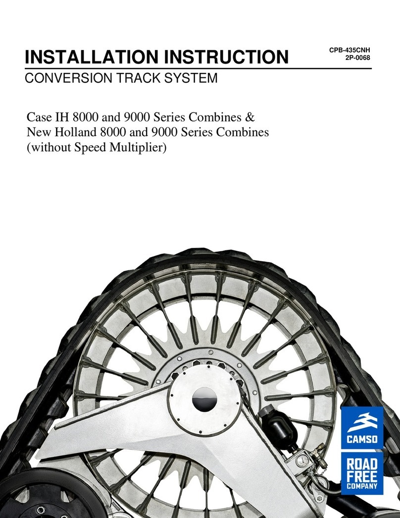
CAMSO 30D23MC User manual

Tractor Systems
Models 30/36D23MC, 30/36D22MC, 24D18C
Serial Numbers 991-2013 & Later
SERVICE MANUAL CPB-447
CONVERSION TRACK SYSTEM


Table Of Contents
1
Conversion Track System Service Manual
Table Of Contents
4
4
6
5
2
3
8
7
1
9
cp1534
Item Page Number
Introduction................................................................................................................................................................3
Machine Identification................................................................................................................................................4
Terminology ...............................................................................................................................................................5
Capacities..................................................................................................................................................................7
Undercarriage Removal And Installation ...................................................................................................................7
1 - Track Removal And Installation ............................................................................................................................9
2 - Front And Rear Idler Wheel Seal And Bearing Removal And Installation ..........................................................15
3 - Midroller Wheel Seal And Bearing Removal And Installation.............................................................................27
4- 24D18C MC Drive Wheel Seal And Bearing Replacement.................................................................................39
5- 30/36D23/22 MC Drive Wheel Seal And Bearing Replacement.......................................................................... 53
6- Tension Cylinder Removal And Installation .........................................................................................................67
7- Manifold And Tension Arm Removal And Installation..........................................................................................73
8- Midroller Axle Remove And Installation...............................................................................................................81
9- Idler Axle And Tension Arm Removal And Installation ........................................................................................85
10 - 30/36D23/22MC Upper And Lower Frame Separation And Rubber Spring Replacement ...............................91

2
Table Of Contents

Introduction
3
Introduction
Service Manual
This service manual was prepared with the latest service information available at the time of publication. Read the
service manual carefully before doing any service on the undercarriage(s).
The photos, illustrations, and data used in this manual were current at the time of printing, but due to possible
production change, your undercarriage can vary slightly. Camso reserves the right make changes to new
production undercarriages as necessary without notification.
WARNING: Some pictures in this manual show the undercarriage with shields removed or
undercarriage removed from the cart or frame to allow for a better view of the subject of the picture.
Important Safety Information
Read and understand this manual, the undercarriage operator's manual, the operation manual for the equipment
the undercarriage is mounted to, and the manual for all attachments before operating, servicing or repairing an
undercarriage.
Most personal injuries occurring during equipment operation, maintenance, or repair are caused by failure to
observe basic safety rules and precautions. In most cases, an injury can be avoided by recognizing hazardous
situations before an injury occurs.
A person must be alert to potential hazards. This person should also have the necessary training, skills and tools to
perform these functions properly.
Improper operation, lubrication, maintenance or repair of this product can be hazardous and could result in injury or
death.
Do not operate or perform any lubrication, maintenance or repair on this product, until you have read and
understood this service manual.
Safety precautions and warnings are provided in this manual and on the product. If these hazard warnings are not
heeded, bodily injury or death could occur to you or to other persons.
Not every possible circumstance that might involve a potential hazard can be anticipated. The warnings in this
publication and on the product are, therefore, not all inclusive. If a tool, procedure, work method or operating
technique that is not specifically recommended by Camso is used, you must satisfy yourself that it is safe for you
and for others.
You must also make sure that the product will not be damaged or be made unsafe by the operation, lubrication,
maintenance or repair procedures that you choose. The information, specifications, and illustrations in this
publication are on the basis of information that was available at the time that this publication was written.
The specifications, torques, pressures, measurements, adjustments, illustrations, and other items can change at
any time. These changes can affect the service that is given to the product. Obtain the complete and most current
information before you start any job. Camso dealers have the most current information available.
Drain all fluids into a suitable container.
Discard any drained fluids and discard any saturated materials according to local regulations.
Use all cleaning solutions with care.
Know the width of your equipment to maintain proper clearance when you operate the equipment near obstacles.
WARNING: When replacement parts are required for this product Camso recommends using
Camso replacement parts. Failure to heed this warning can lead to premature failures, product
damage, personal injury or death.

Introduction
4
Machine Identification
Product Identification Information
Plate Locations
The product serial number will be used to identify an
undercarriage.
NOTE: Some older plates will have Camoplast in
place of Camso.
Right Undercarriage Serial Number:
_________________________________
Left Undercarriage Serial Number:
_________________________________
Part and Serial Number Location (Track)
The track part numbers as well as the serial numbers
are both located on the edge strip of the track.
NOTE: Future track serial numbers will replace Camoplast with Camso.
• Camso Part Number - 1
• Date Code - MMYY
• Serial Number - 0000
cp1750
cp1751

Introduction
5
CTS Track System Terminology
1. Front Idlers
2. Rear Idlers
3. Midrollers
4. Tension Cylinder
5. Tensioner Valve
6. Tensioner Link
7. Track Frame
8. Drive Wheel
Rubber Track Terminology
Camso tracks are constructed using a combination of natural and synthetic rubber in combination with steel
reinforcing plies and a continuous wound main cable. The main cable gives the track tension strength, while at the
same time maintaining lateral flexibility. The bias and the reinforcement plies protect the main cable, provide good
internal track alignment, and further increase lateral stiffness to better distribute loads across the track width.
The treadbars are molded into
specific shapes.
To discuss tracks, wear
characteristics, and track issues
better, certain terms must be
defined as they are frequently
referenced throughout the
document. The illustration
shows some of the basic
terminology used when referring
to track construction:
cp1537
1
6
5
8
7
2
4
3
cp0324
Guide or
Inside (ID)
Surface
Drive Lug
Carcass
Main Cables
Alignment
Plies Reinforcement
Plies
Treadbars

Introduction
6
Basic Rules for Maximizing Track Life
The basic rules in maximizing track life are:
• Follow the correct break-in procedures
• Maintain the proper track alignment
• Know ways to maximize the treadbar life
• Use the correct operational techniques
1. New Track Break-in
Tracks (specifically the drive lugs) will benefit greatly from the correct break-in procedures. The correct break-in
can help reduce the initial amount of guide lug and midroller wear. During the break-in period, the track
components undergo a polishing-in process. New rubber surfaces benefit from contact with the dry soil in order to
facilitate smooth break-in and minimize guide lug scuffing. Tracks should be operated in dry soil as soon as
possible. A significant amount of operation, especially roading, before introduction into the soil should be avoided.
Rule #1 - You must always break-in a new set of tracks, if possible, in dry and dusty conditions.
Rule #2 - Always avoid extended roading at high speeds with a new set of tracks during the break-in period, or
guide lug and wheel edge damage could result.
2. Track Alignment
The Conversion Track System is designed without a track alignment adjustment. The tracks will align themselves
and there is no need to adjust the alignment.

Required Tools And Capacities
7
Capacities
Idler hub capacity ...................................................................................................................................236 ml (8 oz)
Midroller hub capacity.............................................................................................................................236 ml (8 oz)
Drive Wheel Hub Capacity
24D18C..........................................................................................................................................1.2 L (41 oz)
30/36D23/22 MC.............................................................................................................................2.2 L (74 oz)
Grease Type ........................................................................................................................................... NLGI GC-LB
Undercarriage Removal And Installation
Refer to the Installation Instruction Manual specific to your machine and model. Installation Instruction Manuals are
available electronically and in paper form. Paper versions can be requested from Camso Product Support at +39
03 07281503 (Europe) or 317-671-7327 (North America and other countries) or by e-mail at
ag.pr[email protected]. Electric versions are at www.camso.co under Agricultural Products and Parts
And Service.
NOTE: Many illustrations in this service manual are of the 24D18C model track system. The size and look of the
24D18C track system is different from the 30/36D23MC and 30/36D22MC models. The disassembly and assembly
procedures are the same except where a NOTE has been added to indicate differences between models.

8
Required Tools And Capacities

1 - Track Removal And Installation
9
Track Removal And Installation
Track Removal
STEP 1
Position the machine on a hard level surface. Loosen
the mounting nuts (1) on both outside idler wheels.
STEP 2
Remove the cap (1) from the tension valve.
STEP 3
Loosen the set screw (1).
cp1534
1
1
cpo457
1
cpo458
1

1 - Track Removal And Installation
10
STEP 4
Install the drain hose (1) on the valve and direct it
into the catch container. Turn the tension valve knob
(2) counterclockwise slowly to open the valve.
cpo532
1
STEP 5
Place a floor jack (1) under the track and tension idler
wheel. Raise the floor jack slowly to compress the
tension cylinder (2). Close the tension valve.
cpo461
1
1
2
STEP 6
Raise the undercarriage until there is approximately
25 mm (1 inch) between the midroller wheels(1) and
the track. Remove both outside idler wheels (2).
NOTE: All four idler wheels (inner and outer) can be
removed to make it easier to remove the track.
cp1534
13
1
22
STEP 7
Raise the undercarriage until the drive lugs (1) will
clear the midroller wheels (2).
cp1532
1
2

1 - Track Removal And Installation
11
STEP 8
Pull the track bottom of the track lugs from under the
midroller wheels.
STEP 9
Use an appropriate lifting device and chain as shown
to lift the track from the drive wheel. Lower the track
to the ground and remove the chain.
IMPORTANT: Only use a chain with sling type hooks.
Do not use GRAB type hooks. Do not use the chain to
transport the track. Use a fork lift or lifting straps to
carry the track.
cp1536
cpo465
1

1 - Track Removal And Installation
12
Track Installation
STEP 10
Position the track parallel to the undercarriage. Use
the chains and lifting device from Step 9 to lift the
track on the drive wheel.
cp0465
STEP 11
Raise the undercarriage to allow the drive lugs (1) on
the track to clear the bottom of the midroller wheels
(2).
cp1536
2
1
STEP 12
Push the track under the midroller wheels (1).
cp1532
1
STEP 13
Lower the undercarriage until the midroller wheels
are 25 mm (1 inch) above the track. Install both idler
wheels (1). Lubricate and install the mounting nuts.
Tighten the nuts to 540 to 660 Nm (396 to 484 ft-lb).
cp1534
1
1

1 - Track Removal And Installation
13
STEP 14
Install the drain hose (1) on the tension valve and
connect to a hydraulic power source. Open the
tension valve (2) and use the hydraulic source to
tension the track until the tension valve gauge shows
1670 ± 70 psi (115 ± 5 bar). Close the valve (2).
STEP 15
Remove the drain hose and wipe any oil from the
coupling. Install the cap (1). Tighten the set screw
(2).
STEP 16
Lower the undercarriage and track to the ground.
Remove all lifting devises from the machine.
cpo532
1
2
cpo459
1
2
cp1534

14
1 - Track Removal And Installation

2 - Front And Rear Idler Wheel Seal And Bearing Removal And Installation
15
Front And Rear Idler Wheel Seal And Bearing Removal
STEP 1
Follow Steps 1 through 6 of the Track Removal
section of this manual to loosen the track. Remove
the idler wheel to be serviced. the process is the
same for all idler wheels.
STEP 2
Place a drop pan under the hub (1). Loosen the six
hub cover mounting bolts (2).
STEP 3
Pull the bottom of the cover slowly away from the hub
and drain the hub.
cp1534
cp1702
1
1
2
cp1703
13

2 - Front And Rear Idler Wheel Seal And Bearing Removal And Installation
16
STEP 4
Remove the six mounting bolts (1) and remove the
hub cover.
cp1702
1
1
STEP 5
Remove the hub cover O-ring (1).
cp0472
1
STEP 6
Bend the locking tab (1) from the hub.
cp0473
1
STEP 7
Use the locknut socket (2P-0085) to remove the
bearing lock nut (1).
cp0474
1

2 - Front And Rear Idler Wheel Seal And Bearing Removal And Installation
17
STEP 8
Remove the locking washer (1).
STEP 9
Remove the hub (1) and outer bearing cone (2).
NOTE: Use the hub (1) to push the bearing (2) from
the axle. On models before TRE0216003 the bearing
(2) is press fit on the axle and will require a puller on
the hub (1) to remove the hub (1) and bearing (2).
On models TRE0216003 and after the bearing is a
slide fit.
STEP 10
Remove the inner bearing cone (1).
NOTE: On models before TRE0216003 the bearing
(1) is press fit on the axle and will require a bearing
splitter / puller to remove the bearing (1) from the
axle. Be careful not to damage the seal holder
behind the bearing (1).
On models TRE0216003 and after the bearing is a
slide fit.
STEP 11
Remove the face seals (1).
NOTE: If replacing the face seals only proceed to
Page 19 and then to Step 14. If there was a bearing
failure proceed to Step 12.
cp0475
1
cp0476
2
1
cp0478
1
cp0480
1

2 - Front And Rear Idler Wheel Seal And Bearing Removal And Installation
18
STEP 12
If replacing the bearings use a bearing driver from
the opposite side to remove the inner (1) and outer
(2) bearing cups. Clean and inspect all parts for wear
or damage.
If the collar ring is damaged or leaking go to the
Tension Idler Axle Removal And Installation or the
Rear Idler Axle Removal And Installation sections fo
this manual for collar ring removal.
cp1706
1
This manual suits for next models
5
Table of contents
Other CAMSO Tractor Accessories manuals
Popular Tractor Accessories manuals by other brands

HOLMS
HOLMS KHV 280 SMS bracket Operator instructions

Tiger
Tiger JD6175R Mounting and operating instructions

GOLDONI
GOLDONI TOSAPRATO TP60 Operation and maintenance

Wallenstein
Wallenstein FXP Series Operator's manual

RTP Outdoors
RTP Outdoors Genesis 10 User manual and parts book

Metal-Fach
Metal-Fach T703A instruction manual