CAMSO CTS User manual

Case IH 8000 and 9000 Series Combines &
New Holland 8000 and 9000 Series Combines
(without Speed Multiplier)
INSTALLATION INSTRUCTION
CONVERSION TRACK SYSTEM
CPB-435CNH
2P-0068

CPB-435CNH Case and New Holland Combines (without speed multiplier) Camso | 04-17 | 2
1.0 Introduction
This Installation manual was prepared with the latest service information available at the time of
publication. Read the installation manual carefully before doing any service on the
undercarriage(s).
The photos, illustrations, and data used in this manual were current at the time of printing, but
due to possible production change, your installation can vary slightly. Camso reserves the right
make changes as necessary without notification.
WARNING
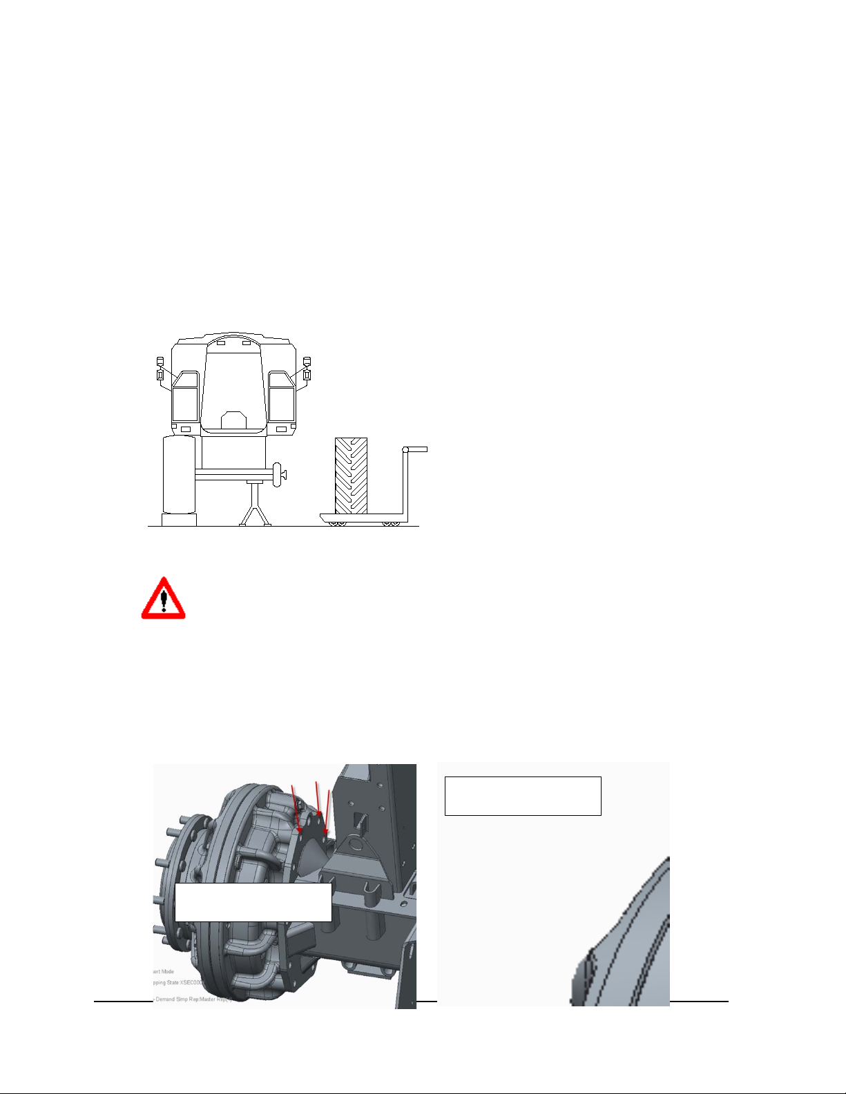
Some pictures in this manual show the undercarriage with shields removed
or undercarriage removed from the cart or frame to allow for a better view
of the subject of the picture.
2.0 Important Safety Information
Read and understand this manual, the undercarriage operator's manual, the operation manual
for the equipment the undercarriage is mounted to, and the manual for all attachments before
installing track system onto the machine.
Most personal injuries occurring during equipment operation, maintenance, or repair are caused
by failure to observe basic safety rules and precautions. In most cases, an injury can be avoided
by recognizing hazardous situations before an injury occurs.
A person must be alert to potential hazards. This person should also have the necessary training,
skills and tools to perform these functions properly.
Safety precautions and warnings are provided in this manual and on the product. If these hazard
warnings are not heeded, bodily injury or death could occur to you or to other persons.
Not every possible circumstance that might involve a potential hazard can be anticipated. The
warnings in this publication and on the product are, therefore, not all inclusive. If a tool,
procedure, work method or operating technique that is not specifically recommended by Camso
is used, you must satisfy yourself that it is safe for you and for others.
You must also make sure that the product will not be damaged or be made unsafe by the
operation, lubrication, maintenance or repair procedures that you choose. The information,
specifications, and illustrations in this publication are on the basis of information that was
available at the time that this publication was written.
The specifications, torques, pressures, measurements, adjustments, illustrations, and other
items can change at any time. These changes can affect the service that is given to the product.
Obtain the complete and most current information before you start any job. Camso dealers have
the most current information available.
WARNING
When replacement parts are required for this product Camso recommends
using Camso replacement parts. Failure to heed this warning can lead to
premature failures, product damage, personal injury or death.

CPB-435CNH Case and New Holland Combines (without speed multiplier) Camso | 04-17 | 3
WARNING
Installation of CTS systems onto any machine requires special adapters
that must be obtained from Camso for proper installation. Failure to heed
this warning can lead to premature failures, product damage, personal
injury or death.
2.0 Special Tools Required for Installation
•30 and 32 mm sockets
•¾” drive torque wrench (range of at least 440 ft-lbs to 620 ft-lbs)
•¾” drive extension (12”)
•¾” drive impact gun
•Lifting straps (capable of lifting 2000 lbs for final drive and speed multiplier install)
•Fork lift or similar lifting device (capable of lifting 5500 lbs)
•Hydraulic Jack (20 ton)
•Blocks (adequate support for holding up combine)
3.0 Installation Notes
•Track systems can be mounted on Case IH 8000 and 9000 Series Combines and New
Holland 8000 and 9000 Series combines.
•Overall machine height is increased by approximately 3” (76 mm) on the front axle.
•Maximum speed will be reduced with the tracks installed. Maximum speed with tracks
installed will be approx. 14 mph.

CPB-435CNH Case and New Holland Combines (without speed multiplier) Camso | 04-17 | 4
4.0 Installation Kit Parts Breakdown
4.1 Case IH 8000 and 9000 Series Combines Fitment Kit
To properly install the CTS track system to a Case IH 7000, 8000, or 9000 Series Combine, the following
component list will be necessary. These components are included in Camso Sales Kit Part Number 2K-
0070. If missing components or there are damaged components, please contact your authorized Camso
Dealer for any replacements.
Part Number
Description
Quantity
1000956
Tension Charging Hose
1
2A-1083
Oscillation Limiter Kit
1
2C-2474
Spacer – Main Hub
2
2F-0392
NORD-LOCK Washer (M22)
20
2F-0415
M22x1.5X100 Hex Bolt 10.9 (Fine)
20
2P-0039
32 mm ¾ Drive Socket
(OD 44mm)
1
1000581*
Oscillation Stop Bracket
2
2F-0462*
M20x2.5x45 Hex Bolt 10.9
8
2F-0325*
M20 Washer
8
* Parts of oscillation stop bracket for the CTS track frame (if not already installed).

CPB-435CNH Case and New Holland Combines (without speed multiplier) Camso | 04-17 | 5
4.2 New Holland 8000 and 9000 CR Series Combines Fitment Kit
To properly install the CTS track system to a New Holland CR or CX Series Combine, the following
component list will be necessary. These components are included in Camso Sales Kit Part Number 2K-
0070. If missing components or there are damaged components, please contact your authorized Camso
Dealer for any replacements.
Part Number
Description
Quantity
1000956
Tension Charging Hose
1
2A-1083
Oscillation Limiter Kit
1
2C-2474
Spacer – Main Hub
2
2F-0392
NORD-LOCK Washer (M22)
20
2F-0415
M22x1.5X100 Hex Bolt 10.9 (Fine)
20
2P-0039
32 mm ¾ Drive Socket
(OD 44mm)
1
1000581*
Oscillation Stop Bracket
2
2F-0462*
M20x2.5x45 Hex Bolt 10.9
8
2F-0325*
M20 Washer
8
* Parts of oscillation stop bracket for the CTS track frame (if not already installed).
4.3 New Holland 8000 and 9000 CR Series Combines Fitment Kit
To properly install the CTS track system to a New Holland CR or CX Series Combine, the following
component list will be necessary. These components are included in Camso Sales Kit Part Number 2K-
0099. If missing components or there are damaged components, please contact your authorized Camso
Dealer for any replacements.
Part Number
Description
Quantity
1000956
Tension Charging Hose
1
1000951
Oscillation Limiter Kit
1
1000956
Tensioning hose - CTS
1
2A-1261-100
Kit – Mounting Adaptor & Spacers – 10 Holes
1
N18-AB01
30mm – ¾ Drive Socket
1
* Parts of oscillation stop bracket for the CTS track frame (if not already installed).

CPB-435CNH Case and New Holland Combines (without speed multiplier) Camso | 04-17 | 6
4.4 Oscillation Limiter Kit (Kit Part Number 2A-1083)
To prevent possible machine and/or undercarriage damage and additional downtime, it is required that the
oscillation limiters be installed. The oscillation limiters are there to reduce the possibility of the CTS track
over oscillating. The table below lists the parts that are included in the oscillation limiter kit which is
included in the fitment kit for your specific combine. If parts are missing or need to be replaced, please
contact your authorized Camso Dealer.
Item #
Part Number
Description
Quantity
1
2C-2421
¾” Spacer
4
2
2C-2426
Attachment Plate
2
3
2F-0031
M20 Washer
12
4
2F-0064
M16x2x60 Bolt 10.9
6
5
2F-0069
M20x2.5x100 Bolt 10.9
4
6
2F-0112
M16 Washer
12
7
2F-0130
M20x2.5x80 Bolt 10.9
8
8
2F-0310
M16 Nut
6
9
2M-066
Clevis
2
10
2S-0463
LH Oscillation Bracket
1
11
2S-0464
RH Oscillation Bracket
1

CPB-435CNH Case and New Holland Combines (without speed multiplier) Camso | 04-17 | 7
4.5 Oscillation Limiter Kit (Kit Part Number 1000951)
To prevent possible machine and/or undercarriage damage and additional downtime, it is required that the
oscillation limiters be installed. The oscillation limiters are there to reduce the possibility of the CTS track
over oscillating. The table below lists the parts that are included in the oscillation limiter kit which is
included in the fitment kit for your specific combine. If parts are missing or need to be replaced, please
contact your authorized Camso Dealer.
Item #
Part Number
Description
Quantity
1
1000952
Limiter LH
1
2
1000953
Limiter RH
1
3
2F-0142
Hex Bolt, ISO 4014, 10.9, A2C – M20x2.5x90
8
4
2F-0275
Contact Washer Type M(NFE 25-511) – A2C
8
5
N39-01
Shackle TSR30
2
6
N39-02
Shackle 7/8’’
2

CPB-435CNH Case and New Holland Combines (without speed multiplier) Camso | 04-17 | 8
5.0 Track System Installation
5.1 Handling of the Track System
The track systems can be handled by fork lifts or by hoists using textile bands. If using a forklift, the track
systems can be lifted from the base of the track system or by carefully sliding the forks through the drive
wheel.
WARNING
Danger of crushing. Use suitable lifting devices (capacity at least 6600 lbs
(3000Kg)), wear safety equipment and observe the safety rules.
WARNING
In case of a fork lift use for handling operations, be careful not to damage
the rubber track. Metal chains or cables are not recommended.
WARNING
Use a chock between each idler wheel and track to prevent the track
system from rolling if using a forklift and handling the track system by the
base.
WARNING
When setting a track system on the ground but off of the machine, place
track system on a flat surface and place a wheel chock in front of and to
the rear of the track system to prevent the track system from rolling.
WARNING
If lifting the track system by placing the forks in the spokes of the
drivewheel, use caution to prevent damage to the drivewheel and
tensioning system (hydraulic accumulator).

CPB-435CNH Case and New Holland Combines (without speed multiplier) Camso | 04-17 | 9
5.2 Track System Installation on Case IH and New Holland Combines
with 2A-1083-100 Limiter Kit
1. Place combine on a level surface and lock the combine harvester to avoid any
movement.
2. Using an adequate lifting device, lift the combine on installation side. Follow procedures
identified in the Combine’s Operator’s Manual to properly remove and handle tires.
Keeping the front axle parallel to the ground will aid in ease of installation.
3. Remove the tire(s) from the axle. Follow procedures identified in the Combine’s
Operator’s Manual to properly remove and handle tires.
WARNING
Safety of the installation depends on the right operation in lifting and
supporting the combine harvester. Check the work area thoroughly and work
in a level area. Respect safe operating practices, operate in conditions of
enough light. Make sure the free spaces of the work area are suitable for the
dimensions of the parts to be handled and for the lifting equipment
maneuvers.
Be careful: risk of injury.
4. Remove the bolts from the locations below from the combine final drive to install the
oscillation limiter.
Front View of axle
Rear View of axle

CPB-435CNH Case and New Holland Combines (without speed multiplier) Camso | 04-17 | 10
Install main oscillation limiter bracket using hardware provided with the installation kit. Torque the 20 mm bolts to
500 ft-lbs (675 Nm).
NOTE: Bracket will point to the rear of the machine.
5. Install secondary oscillation bracket. Torque the 20 mm bolts to 500 ft-lbs (675 Nm) and
16 mm bolts to 250 ft-lbs (345 Nm).

CPB-435CNH Case and New Holland Combines (without speed multiplier) Camso | 04-17 | 11
6. Install oscillation stop bracket onto the CTS
track frame (if not already installed). Install
the bracket to CTS frame to the rear of the
drive wheel. Install oscillation stop bracket
using 4 M20 bolts and 4 M20 lock washers.
Torque bolts to 460 ft-lbs (620 Nm).
NOTE: Older CTS units use a fine
threaded bolt. Model year 2015 and
newer CTS units use a coarse threaded
bolt. Torque remains the same for both
bolt styles
7. Identify if the combine has axle extensions
installed or not. Combine axle extensions are a
factory option when purchasing a combine.
Although, a large portion of the combines in
North America have the axle extensions, it is
still important to verify that the combine has the
axle extensions installed to determine best
installation of the CTS track systems.
8. Install the track system onto the combine axle. Take care that the front of the track is on
the tensioning cylinder side.
a. Combines with axle extensions already installed.
No additional changes are required and CTS
should be bolted directly (with the addition of the
spacer plate included in the fitment kit) to the
combine axle. Install spacer plate onto the axle
hub.
NOTE: The wheel studs are not used when
mounting the CTS to the combine axle. Only the
thru bolts from the CTS drivewheel and threading
directly into the axle housing are used. These
bolts are supplied with the fitment kit.
Combine
Axle
Extension

CPB-435CNH Case and New Holland Combines (without speed multiplier) Camso | 04-17 | 12
b. Combines without axle extensions installed.
i. Preferred CTS Installation
•Install Axle Extensions onto
combine. Please contact your
local dealer for parts and
instructions to install the axle
extensions.
ii. Recommended CTS Installation
(without axle extensions)
•Bolt CTS directly to axle (with
addition of the spacer plate
included in the fitment kit).
•Minor modifications to the
combine will be required in
order for the track to clear.
•NOTE: This allows
approximately 2.5 ± 1 inch (65 ±
25 mm) of clearance between the track and the combine.
iii. Optional CTS Installation (without axle extensions)
•Use the spacer
plate and adapter
plate
•Some
modifications to
the machine may
be necessary to
prevent track
system from
contacting
combine.
•NOTE: This will
allow
approximately 7.5
± 1 inch (190 ± 25
mm) of clearance
between the track
and combine
•NOTE: Higher stress loads will be placed on the bolted joint
•NOTE: Limit high dynamic loading. Inspect bolted joint during daily
inspection, especially if running with large headers and wet heavy
crops
•NOTE: Additional parts will need to be purchased from Camso in
order to install the CTS in this manner.
Wheel/Track
mounting flange
CTS
Drive
Sprocket
Adapter Plate
Spacer Plate

CPB-435CNH Case and New Holland Combines (without speed multiplier) Camso | 04-17 | 13
WARNING
Should a motorized lifting device be used, assistance on ground during
operation of handling, coupling and assembly is needed.
Do not stay between lifting device and track and between track and combine
harvester.
Be careful: risk of injury.
9. Install the 3 or 4 reachable bolts in the
flange holes of the track and tighten
to 220 ft-lbs (300 Nm). Coat threads
of the bolt with engine oil prior to
installing.
NOTE: The mounting bolts are
included in the fitment kit.
10. Repeat the operation on the
opposite side to install the second
track.
11. Once the machine is lowered to
the ground, move it forward or
backward slowly to uncover the remaining bolt holes.
12. Stop the machine and insert the remaining bolts on both track systems; tighten the bolts
to 220 ft-lbs (300 Nm). Coat threads of the bolt with engine oil prior to installing.
NOTE: A 32 mm socket is provided with the fitment kit. This socket is necessary for the
socket to fit onto the head of the bolt and clear the CTS frame. Additional sockets are
available for purchase from Camso.
13. Finally, tighten all the bolts in cross sequence, moving the combine harvester
accordingly. Mounting bolts should be torqued to 500 ft-lbs (670 Nm) for combines using
M22 bolts.
NOTE: Mounting bolt torque should be checked regularly during use. Please reference
the SCHEDULED MAINTENANCE section of the the Operation and Maintenance Manual
(OMM) for additional information.

CPB-435CNH Case and New Holland Combines (without speed multiplier) Camso | 04-17 | 14
14. Connect Oscillation Limiters to the CTS track
frame using the clevis.
WARNING
Install original or backup protections and the ladder in conformity with the
safety rules before starting up the engine.
WARNING
The rubber track has the possibility to move transversally ¼ - ½ in (8-10
mm) each side. Verify that clearance between the track and the combine
harvester body is suitable in all pivoting positions of the track.
15. Drive machine around for 5
minutes. Recheck mounting bolt
torque. Mounting bolts should be
torqued to 500 ft-lbs (670 Nm).
Repeat process until no
additional bolt rotational
movement occurs.
16. After 1 hour of use, retorque mounting bolts to 500 ft-lbs (670 Nm). Repeat hourly check
until no further bolt rotational movement occurs.
WARNING
•It is important to follow the installation instructions and to use a
calibrated torque wrench to ensure bolts are properly torqued. Failure
to do so may result in the CTS mounting bolts coming loose and the
bolts breaking resulting in downtime and possible damage to the
combine and CTS.

CPB-435CNH Case and New Holland Combines (without speed multiplier) Camso | 04-17 | 15
5.3 Track System Installation on Case IH and New Holland Combines
with 1000951 Limiter Kit
17. Place combine on a level surface and lock the combine harvester to avoid any
movement.
18. Using an adequate lifting device, lift the combine on installation side. Follow procedures
identified in the Combine’s Operator’s Manual to properly remove and handle tires.
Keeping the front axle parallel to the ground will aid in ease of installation.
19. Remove the tire(s) from the axle. Follow procedures identified in the Combine’s
Operator’s Manual to properly remove and handle tires.
WARNING
Safety of the installation depends on the right operation in lifting and
supporting the combine harvester. Check the work area thoroughly and work
in a level area. Respect safe operating practices, operate in conditions of
enough light. Make sure the free spaces of the work area are suitable for the
dimensions of the parts to be handled and for the lifting equipment
maneuvers.
Be careful: risk of injury.
20. Remove the bolts from the locations below from the combine final drive to install the
oscillation limiter.

CPB-435CNH Case and New Holland Combines (without speed multiplier) Camso | 04-17 | 16
21. Install main oscillation limiter bracket using hardware provided with the installation kit.
Torque the 20 mm bolts to 500 ft-lbs (675 Nm).
NOTE: Bracket will point to the rear of the machine.
22. Install oscillation stop bracket onto the CTS
track frame (if not already installed). Install
the bracket to CTS frame to the rear of the
drive wheel. Install oscillation stop bracket
using 4 M20 bolts and 4 M20 lock washers.
Torque bolts to 460 ft-lbs (620 Nm).
NOTE: Older CTS units use a fine
threaded bolt. Model year 2015 and
newer CTS units use a coarse threaded
bolt. Torque remains the same for both
bolt styles

CPB-435CNH Case and New Holland Combines (without speed multiplier) Camso | 04-17 | 17
23. Identify if the combine has axle extensions
installed or not. Combine axle extensions are a
factory option when purchasing a combine.
Although, a large portion of the combines in
North America have the axle extensions, it is
still important to verify that the combine has the
axle extensions installed to determine best
installation of the CTS track systems.
24. Install the track system onto the combine axle. Take care that the front of the track is on
the tensioning cylinder side.
a. Combines with axle extensions already installed.
No additional changes are required and CTS
should be bolted directly (with the addition of the
spacer plate included in the fitment kit) to the
combine axle. Install spacer plate onto the axle
hub.
NOTE: The wheel studs are not used when
mounting the CTS to the combine axle. Only the
thru bolts from the CTS drivewheel and threading
directly into the axle housing are used. These
bolts are supplied with the fitment kit.
b. Combines without axle extensions installed.
i. Preferred CTS Installation
•Install Axle Extensions onto
combine. Please contact your
local dealer for parts and
instructions to install the axle
extensions.
ii. Recommended CTS Installation
(without axle extensions)
•Bolt CTS directly to axle (with
addition of the spacer plate
included in the fitment kit).
•Minor modifications to the
combine will be required in
order for the track to clear.
Combine
Axle
Extension

CPB-435CNH Case and New Holland Combines (without speed multiplier) Camso | 04-17 | 18
•NOTE: This allows approximately 2.5 ± 1 inch (65 ± 25 mm) of
clearance between the track and the combine.
iii. Optional CTS Installation (without axle extensions)
•Use the spacer
plate and adapter
plate
•Some
modifications to
the machine may
be necessary to
prevent track
system from
contacting
combine.
•NOTE: This will
allow
approximately 7.5
± 1 inch (190 ± 25
mm) of clearance
between the track
and combine
•NOTE: Higher stress loads will be placed on the bolted joint
•NOTE: Limit high dynamic loading. Inspect bolted joint during daily
inspection, especially if running with large headers and wet heavy
crops
•NOTE: Additional parts will need to be purchased from Camso in
order to install the CTS in this manner.
WARNING
Should a motorized lifting device be used, assistance on ground during
operation of handling, coupling and assembly is needed.
Do not stay between lifting device and track and between track and combine
harvester.
Be careful: risk of injury.
25. Install the 3 or 4 reachable bolts in
the flange holes of the track and
tighten to 220 ft-lbs (300 Nm).
Coat threads of the bolt with
engine oil prior to installing.
NOTE: The mounting bolts are
included in the fitment kit.
26. Repeat the operation on the
opposite side to install the second
track.
Wheel/Track
mounting flange
CTS
Drive
Sprocket
Adapter Plate
Spacer Plate

CPB-435CNH Case and New Holland Combines (without speed multiplier) Camso | 04-17 | 19
27. Once the machine is lowered to the ground, move it forward or backward slowly to
uncover the remaining bolt holes.
28. Stop the machine and insert the remaining bolts on both track systems; tighten the bolts
to 220 ft-lbs (300 Nm). Coat threads of the bolt with engine oil prior to installing.
NOTE: A 32 mm socket is provided with the fitment kit. This socket is necessary for the
socket to fit onto the head of the bolt and clear the CTS frame. Additional sockets are
available for purchase from Camso.
29. Finally, tighten all the bolts in cross sequence, moving the combine harvester
accordingly. Mounting bolts should be torqued to 500 ft-lbs (670 Nm) for combines using
M22 bolts.
NOTE: Mounting bolt torque should be checked regularly during use. Please reference
the SCHEDULED MAINTENANCE section of the the Operation and Maintenance Manual
(OMM) for additional information.
30. Connect Oscillation Limiters to the CTS track
frame using the clevis.
WARNING
Install original or backup protections and the ladder in conformity with the
safety rules before starting up the engine.
WARNING
The rubber track has the possibility to move transversally ¼ - ½ in (8-10
mm) each side. Verify that clearance between the track and the combine
harvester body is suitable in all pivoting positions of the track.

CPB-435CNH Case and New Holland Combines (without speed multiplier) Camso | 04-17 | 20
31. Drive machine around for 5
minutes. Recheck mounting bolt
torque. Mounting bolts should be
torqued to 500 ft-lbs (670 Nm).
Repeat process until no
additional bolt rotational
movement occurs.
32. After 1 hour of use, retorque mounting bolts to 500 ft-lbs (670 Nm). Repeat hourly check
until no further bolt rotational movement occurs.
WARNING
•It is important to follow the installation instructions and to use a
calibrated torque wrench to ensure bolts are properly torqued. Failure
to do so may result in the CTS mounting bolts coming loose and the
bolts breaking resulting in downtime and possible damage to the
combine and CTS.
Table of contents
Other CAMSO Tractor Accessories manuals