Canary EWACT 101 User manual

USER MANUAL
EWACT 101
Electrified Water and Current Tester

Page 2of 16
1Table of Contents
1Table of Contents....................................................................................................................... 2
2Introduction ................................................................................................................................ 3
2.1 Intended Use ....................................................................................................................... 3
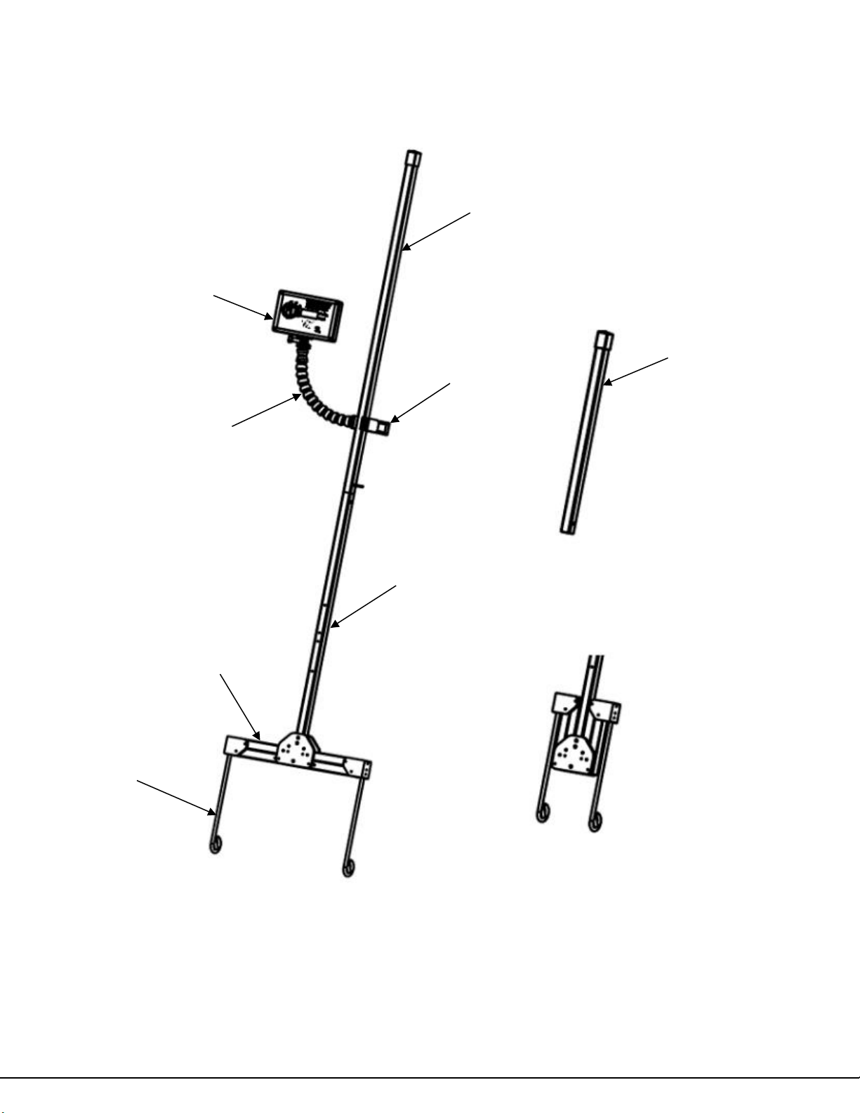
3Parts of the CANARY ................................................................................................................ 4
4Safety Precautions..................................................................................................................... 6
5Functions ...................................................................................................................................... 7
6Procedure for Operation......................................................................................................... 8
6.1 Assemble the CANARY..................................................................................................... 8
6.2 Make a Grounded Connection ...................................................................................... 8
6.3 Operation Modes ............................................................................................................... 9
6.3.1 Unit Test Mode........................................................................................................... 9
6.3.2 Voltage to Ground Mode ........................................................................................ 9
6.3.3 Direction Mode ........................................................................................................10
6.4 Disassemble the CANARY.............................................................................................10
7Care and Maintenance...........................................................................................................11
7.1 General Care ......................................................................................................................11
7.2 Battery Replacement......................................................................................................11
7.3 In Case of Difficulty.........................................................................................................11
7.4 Probes..................................................................................................................................12
8Specifications ............................................................................................................................12
8.1 General Specifications ...................................................................................................12
8.2 Safety Standards ..............................................................................................................12
9Technical Support ...................................................................................................................13
10 Warranty.....................................................................................................................................14
10.1 Warranty Card..............................................................................................................15

Page 3of 16
2Introduction
Thank you for purchasing the ADH CANARY. An Alternating / Direct Current
(AC/DC) electricity detector. The first of its kind, this device can quickly and
efficiently detect the presence of AC and DC electricity of 1 volt and greater in
fluids, and in many cases the direction from which the current is introduced.
2.1 Intended Use
While the unit has been designed to detect AC electricity in a conductive fluid,
the main purpose for its development is to detect stray voltage in water where
personal hazards could exist. This includes marinas, swimming pools, hydro pits,
subway tunnels, flooded basements, data centers, electric car accidents, or any
other environment where water could potentially be exposed to electricity posing
a hazard to life and property.

Page 4of 16
3Parts of the CANARY
Note: Wiring Harness and 15' Ground Adapter Cord not shown.
Short Handle
Long Handle
Head Module
Gooseneck
Collapsed Position
Expanded Position
Probe Arms
Clamp
Base Unit
Probes

Page 5of 16
Head Module
Contents
(Owner's Manual not shown)

Page 6of 16
4Safety Precautions
Warning!
To avoid possible electric shock or personal injury, follow these
guidelines:
Use this device only as specified in this manual or the protection provided
by the CANARY might be impaired.
Do not use the device if it is damaged. Before you use the CANARY,
inspect the case. Look for cracks or missing plastic. Pay particular
attention to the insulation surrounding the connector of the cable harness.
The presence of electricity in any fluid can potentially be lethal.
Never touch the water being tested!
A fault can potentially appear and disappear as equipment is switched on
or off.
The CANARY is designed to assist in the process of locating faults.
Caution must always be used as more than one fault may be present.
The manufacturer cannot possibly anticipate every possible circumstance
that might involve a hazard. The warnings in this manual, and tags and
decals affixed to this unit are, therefore, not all-inclusive. If you use a
procedure, work method or operating technique that the manufacturer
does not specifically recommend, you must satisfy yourself that it is safe
for you. Also, you must always make sure to use the Unit Test function
before and after each use to verify the test unit is functioning correctly.
DO NOT grab below the indicated line duringuse to avoid personal shock.
DO NOT use this product outside when it is raining or during
thunderstorms.
This product is intended to be used by trained professionals EG; first
responders, fire fighters, electricians, technicians, plumbers and or those
trained or aware of the danger of electricity passing through water or fluids.
The Probes are designed to be submerged in water up to the bottom of
the Probe Arms in the extended position.

Page 7of 16
5Functions
The CANARY uses two pre-set tests for the detection of AC or DC in fluids
combined with a self-test function.
1. Self-Test - The CANARY unit is equipped with a Unit Test mode to ensure
the operator that the unit is operating correctly
2. Presence of Stray Electricity - In the Voltage to Ground mode, the CANARY
will alert the operator with a visual and audible alarm when electrical current
of 1 volt or greater is present.
3. Direction of Electrical Source - In the Direction mode, the CANARY will
guide the operator toward the power source by increase of voltage readings
when electrical current of 1 volt or greater is present.

Page 8of 16
6Procedure for Operation
6.1 Assemble the CANARY
1. Place case on a flat, stable surface.
2. Remove the Base Unit from the case.
3. Select Long or Short Handle, slide in place then secure with handle
locking pin.
4. Remove Head Module from case and connect the Gooseneck to the Head
Module if not already connected.
5. Clamp the Head Module assembly to the Handle in the preferred position.
6. Connect the Wiring Harness to the Head Module assembly if required.
7. Unfold probes from the storage position by removing the quick release
pins and unfold the probes. Reinstall pins to secure the probe arms in the
extended position.
8. The unit is now ready to use.
6.2 Make a Grounded Connection
This step is required when using the Voltage to Ground mode. This allows the
meter to reference accurate ground and precise voltage at the test location and
should always be the first test performed after Unit Test.
1. Using the supplied “Green” CSA/UL approved 3 prong Ground Adapter
Cord, plug into the nearest AC outlet and connect it to the CANARY
electrical connector on the unit's handle.
NOTE: You may use a maximum 200 feet of commercial extension cord
connected to the CANARY electrical adapter cord as required to facilitate the
ground connection.
IMPORTANT: THE CANARY DOES NOT USE AC POWER,
EVEN WHEN CONNECTED TO A GROUND ADAPTER CORD
FOR GROUNDING REFERENCE.

Page 9of 16
6.3 Operation Modes
6.3.1 Unit Test Mode
The CANARY has a built-in self-test feature which allows you to verify the unit is
in good working order and the battery has sufficient power.
Configuration
Power switch to "On"
Selector switch positioned to Unit Test
Probes out of the fluid to be tested
Test
1. Push and hold the unit test button. The indicator light will flash, and the
audible buzzer will sound. If they do not stop, replace the 9V battery. If
they do not flash or sound call Customer Support.
6.3.2 Voltage to Ground Mode
Configuration
Power switch to "On"
Selector switch positioned to Voltage to Ground
“Green/Yellow” ground adapter cord connected to AC outlet to facilitate
ground
Probes suspended in fluid to be tested
Test
1. If electricity of 1 volt or greater is present, the indicator light will flash and
the audible buzzer will sound. The voltmeter will display the amount of
electricity present at the user’s location. If AC is detected the warning light
marked AC Detected will be activated along with the buzzer.
CAUTION:
Voltage readings will increase the closer the probes get to the source.
Alternatively, the voltage will decrease as the probes are moved away from
the source.

Page 10 of 16
6.3.3 Direction Mode
Configuration
Power switch to "On"
Selector switch positioned to Direction
Probes suspended in fluid to be tested
Test
1. This test measures the gradient voltage between the two probes. When
electricity is present and the alarm is activated, slowly rotate the probe
handle while observing the meter readout. You will observe the voltage
change, as shown by the meter readout. When the highest number is
reached, the probes horizontal arms will be parallel to the direction of the
source. If possible, move the unit in the indicated direction verifying the
maximum voltage is kept on the meter. As the unit gets closer to the
source, the voltage will increase on the meter.
6.4 Disassemble the CANARY
NOTE: Always perform a Self-Test at the end of use to verify the unit is still in
working order. This will ensure that a fault did not occur during use that would
give a false indication of an area being void of stray electrical current.
1. Place storage case on a flat, stable surface.
2. Return the probes to the storage position by removing the quick release
pins and folding the probes. Reinstall pins to secure the probe arms in the
storage position.
3. Disconnect the Wiring Harness from the Head Module assembly if
required.
4. Unclamp the Head Module assembly from the handle.
5. Remove the long or short handle.
6. Disconnect the gooseneck from the Head Module if required.
7. Place the components in the case.
8. The unit is now ready to be stored.

Page 11 of 16
7Care and Maintenance
7.1 General Care
Ensure the unit is dry after use and prior to storage.
If used in salt water, rinse exposed parts, except the Head Module, with
fresh water and dry prior to storage.
Self-test the unit before and after each use.
Even if not required, replace the battery every 12 months.
Recommended annual calibration
7.2 Battery Replacement
1. Turn the unit “Off” and remove the wiring harness from the head unit.
2. Place meter on flat surface.
3. Use a 1/16" Allen key to loosen and remove selector switch.
4. Use a Philips screwdriver to loosen and remove 4 cover screws.
5. Lift cover off and replace 9v battery located inside.
6. Replace screws and selector switch.
7.3 In Case of Difficulty
If the CANARY does not work properly:
1. Review this manual to verify correct operation.
2. Check and replace the battery if needed.
3. Examine the case for damage. If damage is detected, contact ADH Inc.
See the “Technical Support” section in this manual.
4. If the unit still does not work, call customer service. If return shipping is
required, ADH Inc. assumes no responsibility for damage in transit.

Page 12 of 16
7.4 Probes
The CANARY ships with two probes that have been designed and tested as an
accessory with this device. These probes are only to be used in its intended
application with the CANARY. Should the probe(s) be damaged or need
replacing, please contact the manufacturer.
8Specifications
8.1 General Specifications
Maximum voltage between any
Terminal and Earth Ground
.................
..
600 V
Battery Type
…………………………………
(1) 9-volt alkaline battery
Battery Life
……………………………………
120 hours minimum
Operating Temperature
……………………..
0 °C to 55 °C / 32°F to 131°F
Storage Temperature
………………………
-21 °C to 60 °C / -5°F to
140°F
Relative Humidity
……………………………
0 % to 90 % (0 °C to 37 °C),
0 % to 65 % (37 °C to 45 °C),
0 % to 45 % (45 °C to 55 °C)
Operating
…………………………………
2,000m Altitude
Storage
………………………………………
2,000m Altitude
Vibration
……………………………………
Random Vibration per MIL-
PRF-28800F Class 2
Shock
…………………………………………
1 meter drop per IEC/EN
61010-1 2nd Edition
Size
……………………………………...........
Case: 51" x 11" x 4"
Fully Extended: 84" x 19" x 3"
Weight
………………………………………
12 lbs
8.2 Safety Standards
CSA CAN/CSA-C22.2 NO. 61010-1:12
CSA CAN/CSA-C22.2 NO. 61010-2-033:14
CSA CAN/CSA-C22.2 NO. 61010-031:17
UL 61010-1
UL 61010-2-033
UL 61010-031
Pollution Degree 2
CATII, Up to 600V
CSA Approved in Canada and USA

Page 14 of 16
10 Warranty
Lifetime Limited Warranty
Each ADH Inc. CANARY will be free from defects in material and workmanship
for its lifetime. As used herein, “lifetime” is defined as seven years after ADH Inc.
discontinues manufacturing the product, but the warranty period shall be at least
ten years from the date of purchase. This warranty does not cover fuses,
disposable batteries, damage from neglect, misuse, contamination, alteration,
accidental or abnormal conditions of operation or handling, including failures
caused by use outside of the product’s specifications, or normal wear and tear of
mechanical components. This warranty covers the original purchaser only and is
not transferable.
For ten years from the date of purchase, this warranty also covers the LCD.
Thereafter, for the lifetime of the CANARY, ADH Inc. will replace the LCD for a
fee based on then current component acquisition costs.
To establish original ownership and prove date of purchase, please complete
and return the warranty card at the end of this manual or register your product
on http://www.ewact.com. ADH will, at its option, repair at no charge, replace or
refund the purchase price of a defective product purchased through an ADH
authorized sales outlet and at the applicable international price. ADH reserves
the right to charge for importation costs of repair/replacement parts if the product
purchased in one country is sent for repair elsewhere.
If the product is defective, contact your nearest ADH authorized service center
to obtain return authorization information, then send the product to that service
center, with a description of the difficulty, postage and insurance prepaid (FOB
Destination). ADH assumes no risk for damage in transit. ADH Inc. will pay return
transportation for product repaired or replaced in-warranty. Before making any
non-warranty repair, ADH Inc. will estimate cost and obtain authorization, then
invoice you for repair and return transportation.
THIS WARRANTY IS YOUR ONLY REMEDY. NO OTHER WARRANTIES,
SUCH AS FITNESS FOR A PARTICULAR PURPOSE, ARE EXPRESSED OR
IMPLIED. ADH Inc. SHALL NOT BE LIABLE FOR ANY SPECIAL, INDIRECT,
INCIDENTAL OR CONSEQUENTIAL DAMAGES OR LOSSES, INCLUDING
LOSS OF DATA, ARISING FROM ANY CAUSE OR THEORY. AUTHORIZED
RESELLERS ARE NOT AUTHORIZED TO EXTEND ANY DIFFERENT
WARRANTY ON ADH Inc’s BEHALF. Since some states do not allow the
exclusion or limitation of an implied warranty or of incidental or consequential
damages, this limitation of liability may not apply to you. If any provision of this
warranty is held invalid or unenforceable by a court or other decision-maker of
competent jurisdiction, such holding will not affect the validity or enforceability of
any other provision.

Page 15 of 16
10.1Warranty Card
WARRANTY CARD
Send this copy to: BFAM Industries, 14106 FM 1097 W, Willis Tx 77318
Product Model Number:
Serial Number:
Date of Purchase:
Where Purchased:
Print Name:
Address:
`
Email:
My signature below acknowledges that I have read, fully understand and accept this limited warranty agreement.
Signature:
Date:
Must return within 30 days of purchase with a copy of dated receipt.
Note: Emailing Warranty Card is acceptable:

Page 16 of 16
Table of contents
Popular Test Equipment manuals by other brands

MONARCH INSTRUMENT
MONARCH INSTRUMENT Phaser-Strobe pbx instruction manual

Keysight Technologies
Keysight Technologies E5405A-Pro Series user guide

TAKAYA
TAKAYA APT-9411 Series Operator's guide

Agilent Technologies
Agilent Technologies 1142A user guide

Uniks
Uniks GHOST METER F user manual

DANPHONE
DANPHONE Futronic GMDSS-AIS-SART user manual

Agilent Technologies
Agilent Technologies 8000 Series datasheet

Tektronix
Tektronix MTS400 Series Quick start user manual

Champion
Champion UH330 ADA Installation & operation manual

JOVA Solution
JOVA Solution ISL-3200 quick start guide

FiT
FiT 333 quick guide

Kyoritsu Electrical Instruments Works, Ltd.
Kyoritsu Electrical Instruments Works, Ltd. KEW3125A instruction manual