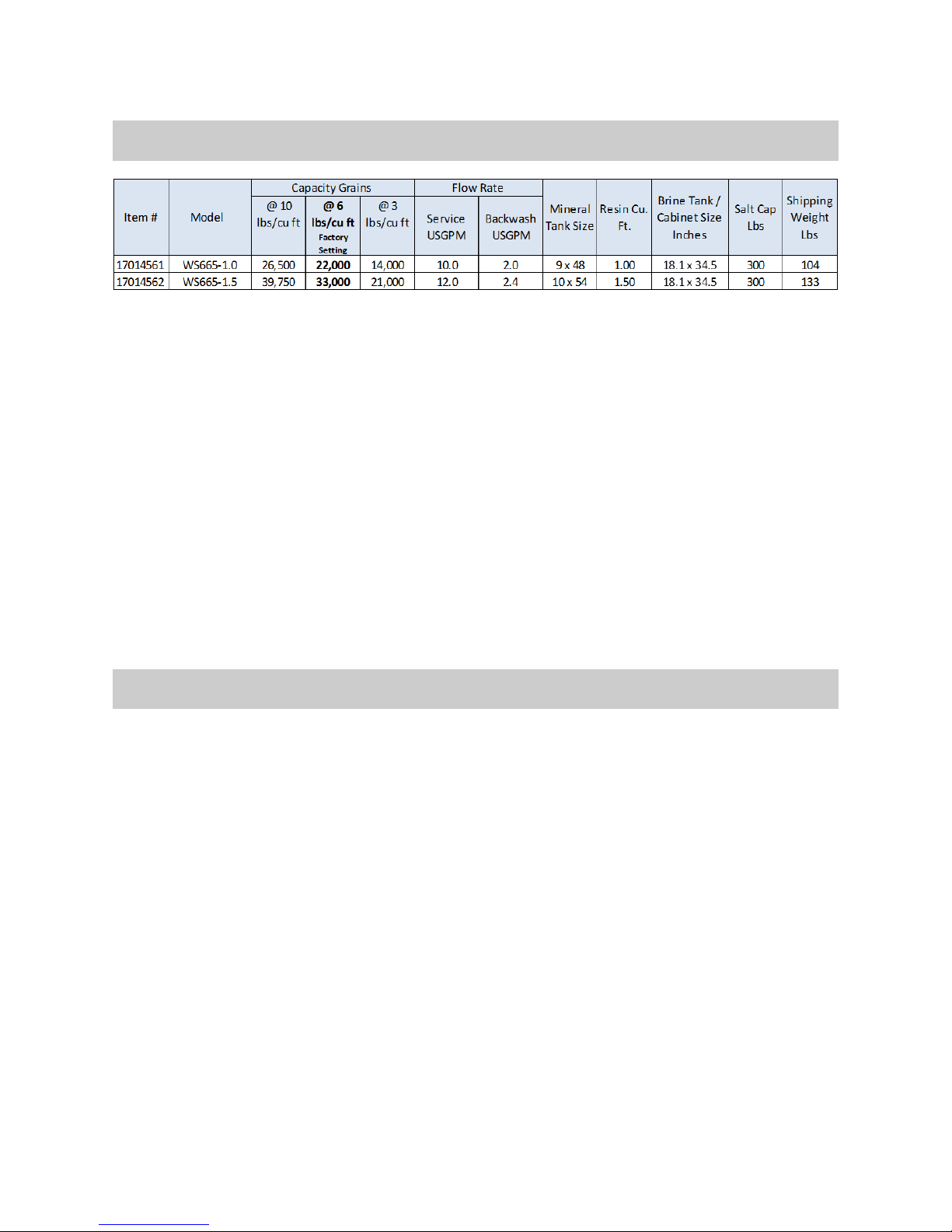
Canature WS665 User manual

WS665
Water Softener
Owners Manual
REVISION # 2
REVISION DATE September 12, 2013
FOLLOWTHE INSTALLATION INSTRUCTIONS CAREFULLY. FAILURE TO
INSTALL THE UNIT PROPERLY VOIDS THE WARRANTY. BEFORE YOU
BEGIN INSTALLATION, READ THIS ENTIRE MANUAL. THEN, OBTAIN ALL
THE MATERIALS AND TOOLS
1. Avoid pinched o-rings during installation by applying (provided with install kit) NSF certified
lubricant to all seals.
2. This system is not intended for treating water that is microbiologically unsafe or of unknown
quality without adequate disinfection before or after the system.

2
Safety Guide
Check and comply with your provincial /
state and local codes. You must follow
these guidelines.
Use care when handling the water soften-
ing system. Do not turn upside down,
drop, drag or set on sharp protrusions.
The water softening system works on 12
volt-60 Hz electrical power only. Be sure to
use only the included transformer.
Transformer must be plugged into an in-
door 120 volt, grounded outlet only.
Use clean water softening salts only, at
least 99.5% pure. NUGGETor PELLET salts
are recommended. Do not use rock, block,
granulated or ice cream making salts.
They contain dirt and sediments, or mush
and cake, and will create maintenance
problems.
Keep the salt lid in place on the softener
unless servicing the unit or refilling with
salt.
WARNING: This system is not in-
tended for treating water that is microbio-
logically unsafe or of unknown quality
without adequate disinfection before or
after the system.
For your safety, the information in this manual must be followed to minimize the risk of
electric shock, property damage or personal injury.
Be sure to check the entire softener for any shipping damage or parts loss. Also note dam-
age to the shipping cartons. Contact the transportation company for all damage and loss
claims. The manufacturer is not responsible for damages in transit.
Small parts, needed to install the softener, are in a parts bag. To avoid loss of the small
parts, keep them in the parts bag until you are ready to use them.
Unpacking / Inspection
PAGE
Unpacking / Inspection 2
Safety Guide 2
Proper Installation 3
Specification 4
Before Starting Installation 4
Installation Instructions 6
System Start Up 8
Programming Instructions 9
About The System 10
Maintenance 12
Sanitizing Procedure 15
Main Repair Parts 16
Trouble Shooting 21
Warranty 22
Table of Contents

3
Proper Installation
This water softening system must be properly installed and located in accordance with the
Installation Instructions before it is used.
Do not
install or store where it will be
exposed to temperatures below freezing or
exposed to any type of weather. Water
freezing in the system will break it. Do not
attempt to treat water over 100°F.
Do not
install in direct sunlight. Excessive
sun or heat may cause distortion or other
damage to non-metallic parts.
Properly ground to conform with all gov-
erning codes and ordinances.
Use only
lead-free solder and flux
for all
sweat-solder connections, as required by
state and federal codes.
Maximum allowable inlet water pressure is
125 psi. If daytime pressure is over 80
psi, night time pressure may exceed the
maximum. Use a pressure reducing valve
to reduce the pressure.
Softener resins may degrade in the pres-
ence of chlorine or chloramines above 2
ppm. If you have chlorine or chloramines
in excess of this amount, you may experi-
ence reduced life of the resin. In these
conditions, you may wish to consider pur-
chasing a whole house carbon filter sof-
tener system with a chlorine reducing me-
dia.
WARNING:
Discard all unused parts and
packaging material after installation. Small
parts remaining after the installation could
be a choke hazard.

4
Specifications
Before Starting Installation
Tools, Pipe, and Fittings, Other Materials
Pliers
Screwdriver
Teflon tape
Razor knife
Two adjustable wrenches
Additional tools may be required if modifi-
cation to home plumbing is required.
Plastic inlet and outlet fittings are included
with the softener. To maintain full valve
flow, 3/4” or 1” pipes to and from the sof-
tener fittings are recommended. You
should maintain the same, or larger, pipe
size as the water supply pipe, up to the
softener inlet and outlet.
Use copper, brass, or PEX pipe and fittings.
Some codes may also allow PVC plastic
pipe.
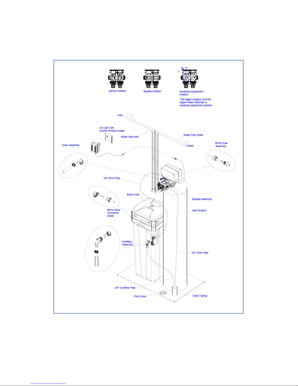
ALWAYS install the included bypass valve,
or 3 shut-off valves. Bypass valves let you
turn off water to the softener for repairs if
needed, but still have water in the house
pipes.
5/8” OD drain line is needed for the valve
drain. A 10’ length of hose is included.
with some models.
A length of 5/8” OD drain line tubing is
needed for the brine tank over flow fitting
(optional).
Nugget or pellet water softener salt is
needed to fill the cabinet or brine tank.
Water Temperature = Min 39°F / Max 100°F
Operating Pressure = Min 35 PSI / Max 125 PSI
Voltage = 110 volts standard
Units contain 8% Super Capacity Ion Exchange Resin
At the stated service flow rates, the pressure drop through
these devices will not exceed 15 psig.
Changing salt settings from factory setting may require
changing injector sizes to achieve stated capacities.
The manufacturer reserves the right to make product im-
provements which may deviate from the specifications and
descriptions stated herein, without obligation to change
previously manufactured products or to note the change.
How Your Water Conditioner Works
The principle behind water softening is simple chemistry. A water softener contains resin
beads which hold electrically charged ions. When hard water passes through the softener,
calcium and magnesium ions are attracted to the charged resin beads. It's the resulting re-
moval of calcium and magnesium ions that produces soft water.
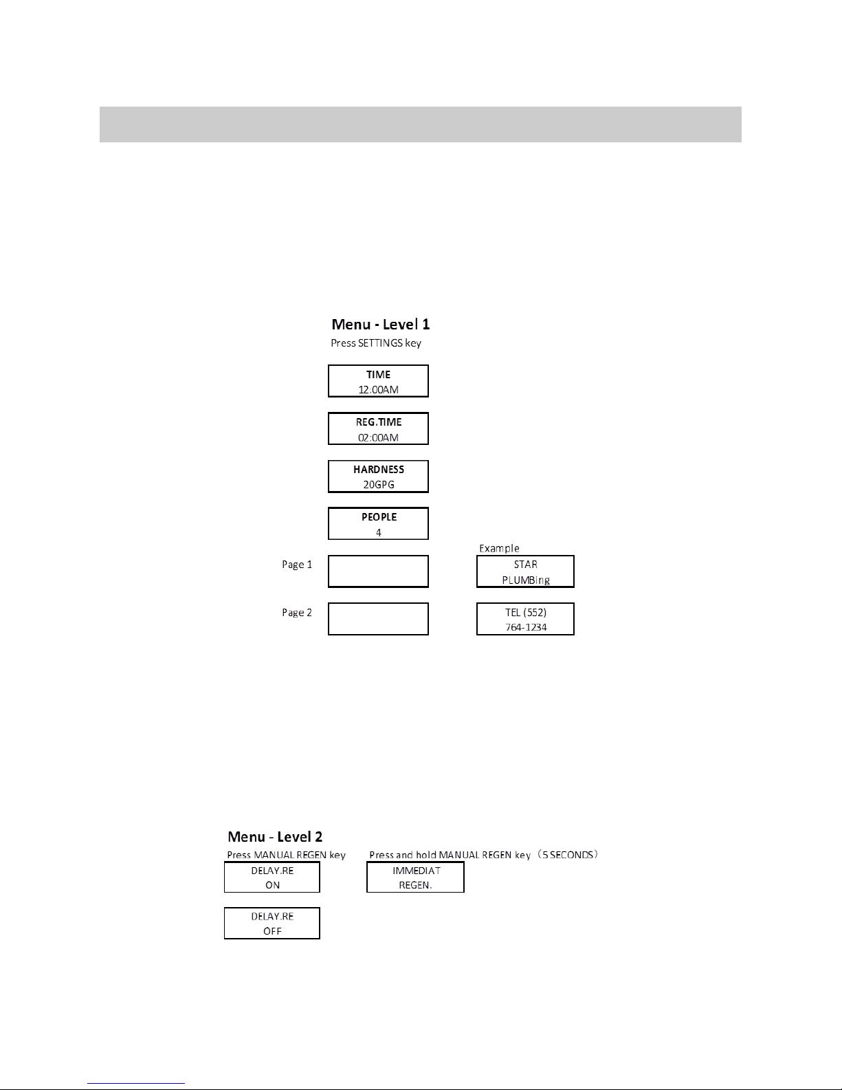
This system is controlled with simple, user-friendly electronics displayed on a LCD screen.
The main page displays the current time and the remaining gallons in meter mode or the
remaining days in calendar clock mode.

5
Place the softener as close as possible to
the pressure tank (well system) or water
meter (city water).
Place the softener as close as possible to a
floor drain, or other acceptable drain point
(laundry tub, sump, standpipe, etc.).
Connect the softener to the main water
supply pipe BEFORE the water heater. DO
NOT RUN HOT WATER THROUGH THE
SOFTENER. Temperature of water pass-
ing through the softener must be less than
100 deg. F.
Keep outside faucets on hard water to
save soft water and salt.
Do not install the softener in a place where
it could freeze. Damage caused by
freezing is not covered by the war-
ranty.
Put the softener in a place water damage
is least likely to occur if a leak develops.
The manufacturer will not repair or pay for
water damage.
A 120 volt electric outlet, to plug the in-
cluded transformer into, is needed within 6
feet of the softener. The transformer has
an attached 6 foot power cable. Extension
cables are available. Be sure the electric
outlet and transformer are in an in-
side location, to protect from wet
weather.
If installing in an outside location, you
must take the steps necessary to assure
the softener, installation plumbing, wiring,
etc., are as well protected from the ele-
ments, contamination, vandalism, etc., as
when installed indoors.
Keep the softener out of direct
sunlight. The sun’s heat may soften and
distort plastic parts.
Where To Install The Softener

6
1. If your hot water tank is electric, turn off the power to it to avoid damage to the element
in the tank.
2. If you have a private well, turn the power off to the pump and then shut off the main wa-
ter shut off valve. If you have municipal water, simply shut off the main valve. Go to the
faucet, (preferably on the lowest floor of the house) turn on the cold water until all pres-
sure is relieved and the flow of water stops.
3. Locate the softener tank and brine tank close to a drain where the system will be in-
stalled. The surface should be clean and level.
4. Connect the inlet and outlet of the softener using appropriate fittings. Perform all plumb-
ing according to local plumbing codes.
Use a ½” minimum pipe or tubing size for the drain line
ON COPPER PLUMBING SYSTEMS BE SURE TO INSTALL A GROUNDING
WIRE BETWEEN THE INLET AND OUTLET PIPING TO MAINTAIN GROUND-
ING.
Any solder joints being soldered near the valve must be done before connecting any piping
to the valve. Always leave at least 6" (152 mm) between the valve being soldered and
joints when soldering pipes that are connected to the valve. Failure to do this could cause
damage to the valve.
5. Connect the drain hose (10 ft included) to the valve and secure it with a hose clamp (also
included). Run the drain hose to the nearest laundry tub or floor drain. This can be ran
up overhead or down along the floor. If running the drain line more than 20 ft overhead,
it is recommended to increase the hose size to 3/4”. NEVER MAKE A DIRECT CONNEC-
TION INTO A WASTE DRAIN. A PHYSICAL AIR GAP OF AT LEAST 1.5” SHOULD BE USED
TO AVOID BACTERIA AND WASTEWATER TRAVELLING BACK THROUGH THE DRAIN
LINE INTO THE SOFTENER.
6. Using the Allen Key (included), place the unit in the bypass position. Slowly turn on the
main water supply. At the nearest cold treated water tap nearby remove the faucet
screen, open the faucet and let water run a few minutes or until the system is free of any
air or foreign material resulting from the plumbing work.
7. Make sure there are no leaks in the plumbing system before proceeding. Close the water
tap when water runs clean.
8. Open the brine tank / cabinet salt lid and add water until there is approximately 3” (75
mm) of water in the tank. Do not add salt to the brine tank at this time.
9. Proceed to start up instructions.
Note: The unit is not ready for service until you complete the start-up instruc-
tions.
Installation Instructions

7
Installation Twin Tank

8
System Start-Up
1. Plug the power transformer into an ap-
proved power source. Connect the power
cord to the valve.
2. When power is supplied to the control, the
screen will display “CANATURE” while it
finds the service position.
3. Manually step the valve past the BRINE
position to the BACKWASH position. If
screen is locked, the screen will display
“PRESS SETTINGS 3S TO UNLOCK”. Fol-
low the instructions and press SETTINGS
for 3 seconds to unlock. Press and hold
the MANUL REGEN. Key for 3 seconds.
Press any key to skip the BRINE cycle.
4. Once in the BACKWASH cycle, open the
inlet on the bypass valve slowly and allow
water to enter the unit. Allow all air to es-
cape from the unit before turning the by-
pass fully open. Then allow water to run
to drain for 3-4 minutes or until all media
fines are washed out of the softener indi-
cated by clear water in the drain hose.
5. Press any button to advance to the RINSE
position. Check the drain line flow. Allow
the water to run for 3-4 minutes or until
the water is clear.
6. Press any button to advance to the REFILL
position. Check that the valve is filling wa-
ter into the brine tank. Allow the valve to
refill for the full amount of time as dis-
played on the screen to insure a proper
brine solution for the next regeneration.
7. The valve will automatically advance to the
SERVICE position. Open the outlet valve
on the bypass, then open the nearest
treated water faucet and allow the water
to run until clear, close the tap and replace
the faucet screen.
8. Add salt into the cabinet / brine tank.
9. Program unit.
Key Pad Configuration
Start-up Instructions
SETTINGS This function is to enter the basic set up information required at the
time of installation.
MANUAL REGEN This button has two functions. The first is to initiate an immediate or
delayed manual regeneration. The second is while in programming
mode, pressing this key allows the user to change the value of each
setting.
DOWN / UP Increase or decrease the value of the settings while in the program-
ming mode.

9
Programming Instructions
Manual Regeneration (Step / Cycle Valve)
1. Press SETTINGS to enter programming. If the system has been inactive, you may
have to hold and press SETTINGS to unlock the display screen. Press UP or DOWN to
select which setting to modify.
2. To adjust a value, MANUAL REGEN. When the display flashes, the value may be
changed. Press UP or DOWN to change the value. Press MANUAL REGEN again to ac-
cept the value.
3. Press UP or DOWN to advance to the next option.
4. At any time, press SETTINGS to return to previous home screen menu.
If screen is locked, press and hold SETTINGS for 3 seconds to unlock. To initiate an imme-
diate regeneration, press and hold the MANUAL REGEN key for 5 seconds. The valve will
immediately start into manual regeneration.
To initiate a delayed regeneration, press the MANUAL REGEN key once to turn on and a re-
generation will be queued at the next pre-set regeneration time (i.e. 2:00 a.m.).. To cancel,
press the MANUAL REGEN key again.

10
Operation During A Power Failure
In the event of a power failure, the valve will keep track of the time and day for 48 hours.
The programmed settings are stored in a non-volatile memory and will not be lost during a
power failure. If power fails while the unit is in regeneration, the valve will finish regenera-
tion from the point it is at once power is restored. If the valve misses a scheduled regen-
eration due to a power failure, it will queue a regeneration at the next regeneration time
once power is restored.
Main Display
When power is supplied to the control, the screen will display TIME OF DAY, GALLONS RE-
MAINING, and DEALER NAME and PHONE NUMBER.
The brine tank is equipped with a safety float which prevents your brine tank from overfill-
ing as a result of a malfunction such as a power failure.
Safety Float
New Sounds
You may notice new sounds as your water softener operates. The regeneration cycle lasts
up to 180 minutes. During this time, you may hear water running intermittently to the drain.
About The System
When the system capacity is near exhausted, a regeneration is necessary to restore the sys-
tem to full capacity. The table below explains the regeneration steps.
Regeneration Process
Step Name Description
#1 Back Wash
Fresh water is introduced to the bottom of the tank flowing upwards expanding the ion
exchange resin to rinse out any dirt or small particles to the drain and to un-compact
the bed to restore full service flow rates.
#2 Brine
The brine solution is introduced slowly from the top of the tank flowing down through
the ion exchange resin pushing the hardness out to drain and restoring system capacity.
#4 Rinse
Fresh water is introduced from the top of the tank flowing down through the ion
exchange resin rinsing any excess brine solution out to the drain.
#5 Refill
Fresh water is added to the salt tank to prepare and insure fully saturated brine for the
next regeneration.

11
Automatic Hard Water Bypass During Regeneration
The regeneration cycle can last 30 to 180 minutes, after which soft water service will be re-
stored. During regeneration, hard water is automatically bypassed for use in the household.
Hot water should be used as little as possible during this time to prevent hard water from
filling the water heater. This is why automatic regeneration is set for sometime during the
night and manual regenerations should be performed when little or no water will be used in
the household.
Normal regeneration time is 2:00 AM.
System Configuration
Injector and Drain Line Flow Control

12
Manual Bypass
In the case of emergency, such as an overflowing brine tank, you can isolate your water
softener from the water supply using the bypass valve located at the back of the control. In
normal operation the bypass is open with the on/off knobs in line with the inlet and outlet
pipes.
To isolate the softener, simply rotate the knobs clockwise (as indicated by the word BYPASS
and arrow) until they lock. You can use your water related fixtures and appliances as the
water supply is bypassing the softener. However, the water you use will be hard. To resume
soft water service, open bypass valve by rotating the knobs counterclockwise.
Maintenance
Adding Salt
Use only NUGGETor PELLET water softener salt. Check the salt level monthly. It is impor-
tant to maintain the salt level above the water level. To add salt, simply lift the salt lid and
add the salt directly into the brine tank. Be sure the brine well cover is on and fill only to
the height of the brine well.
Bridging
Humidity or wrong type of salt may create a cavity between the water and the salt. This ac-
tion, known as “bridging”, prevents the brine solution from being made, leading to your wa-
ter supply being hard.
If you suspect salt bridging, carefully pound on the outside of the brine tank or pour some
warm water over the salt to break up the bridge. This should always be followed up by al-
lowing the unit to use up any remaining salt and then thoroughly cleaning out the brine
tank. Allow two hours to produce a brine solution, then manually regenerate the softener.

13
Cleaning or Replacing Injectors
Sediment, salt and silt will restrict or clog the injector. A clean water supply and pure salt
will prevent this from happening.
The injector assembly is located on the right side of the control valve. This assembly is
easy to clean.
1. Shut off the water supply to your softener and reduce the pressure by opening a cold
soft water faucet.
2. Using a screwdriver, remove the two screws holding the injector cover to the control
valve body.
3. Carefully remove the assembly and disassemble as shown above. The injector orifice
is removed from the valve body by carefully turning it out with a large screwdriver. Re-
move the injector throat the same way.
4. Carefully flush all parts including the screen. Use a mild acid such as vinegar or Pro-
Rust Out to clean the small holes in the orifice and throat.
5. Re-assemble using the reverse procedure.

14
Replacing Brine Line Flow Control (BLFC)
1. Remove the red clip that secures the brine elbow.
2. Remove the BLFC holder from the elbow fitting.
3. Split the BLFC holder apart and remove the flow washer.
4. Reassemble using the reverse procedure.
TIP: Markings on the
BLFC washer should face
the direction as shown
here.
Replacing Drain Line Flow Control (DLFC)
1. Remove the red clip that secures the drain line elbow.
2. Remove the BLFC washer from the elbow fitting.
3. Reassemble using the reverse procedure.

15
Care of Your System
To retain the attractive appearance of your new water softener, clean occasionally with mild
soap solution. Do not use abrasive cleaners, ammonia or solvents. Never subject your sof-
tener to freezing or to temperatures above 100°F.
Resin Cleaner
An approved resin cleaner must be used on a regular basis if your water supply contains
iron. The amount of resin cleaner and frequency of use is determined by the quantity of
iron in your water (consult your local representative or follow the directions on the resin
cleaner package).
Sanitizing Procedure
Care is taken at the factory to keep your water softener clean and sanitary. Materials used
to make the softener will not infect or contaminate your water supply, and will not cause
bacteria to form or grow. However, during shipping, storage, installing and operating, bac-
teria could get into the softener. For this reason, sanitizing as follows is suggested when in-
stalling.
Sani-System Liquid Sanitizer Concentrate
Item# 80030021—Softener Sanitizer 0.25 fl.oz (24 Pack)
1. Be sure to complete all installation steps, including programming.
2. For effective and complete sanitization, Sani-System Liquid Sanitizer Concentrate is rec-
ommended. Pour one 0.25 fl. Oz. package into the brine well located in the cabinet or
brine tank. (Alternative use 3/4 oz of common 5.25% household bleach)
3. Start an immediate regeneration. (See page 11)
4. The Softener Sanitizer Solution is drawn into and through the water softener to sanitize
it. This sanitizing regeneration is over in about two hours. Then, soft water is available
for your use.
NOTE: Sanitizing is recommended by the Water Quality Association for disinfecting. On
some water supplies, they suggest periodic sanitizing.

16
Main Repair Parts - Connectors
A A A
B
D
F
E
A
C
Replacement Part Number Part Description DWG # Quantity
60010020 3/4" NPT ELBOW A 2
60010019 1" NPT STRAIGHT A 2
60010023 3/4" NPT STRAIGHT A 2
60010079 VALVE COUPLING INLET B 1
60010101 VALVE COUPLING OUTLET (METER SIDE) C 1
60010025 PLASTIC SECURE CLIP D 2
60010046 BYPASS SS CLIP E 2
60010047 BYPASS SS SCREW F 2
REPLACEMENT PARTS - CONNECTORS

17
Control Valve Exploded View

18
Control Valve Parts List
Item No. Part No. Part Discription Quantity
A01 05056087
Screw-M5×12(Hexagon) 3
A02 05056088
Screw-M5×16(Hexagon with Washer) 2
A03 05056047
End Plug Retainer 1
A04 05010081
Bnt65 Piston Rod 1
A05 05056097
Piston Pin 1
A06 05056023
End Plug 1
A07 05056070
Quad Ring 2
A08 05056024
End Plug Washer 1
A09 05056022
Piston Retainer 1
A10 05056181
Piston (Electrical) 1
A11 05056104
Muffler 1
A12 05056021
Spacer 4
A13 05056073
Seal 5
A14 05056019
Bnt65 Valve Body 1
A15 05056063
O-ring-φ78.74×5.33 1
A16 05056129
O-ring-φ23×3 4
A17 05056025
Adaptor Coupling 2
A18 05056044
Adaptor Clip 2
A19 05056090
Screw-ST4.2×13(Hexagon with Washer) 2
A20 21709003
Secure Clip 2
A21 05056140
Valve Connector 1
A22 05056065
O-ring-φ23.6×2.65 2
A23 21319006
Screw Adaptor 2
A24 26010103
O-ring-φ25×3.55 1
A25 07060007
Valve Bottom Connector 1
A26 13000426
Screw-ST2.9×13(Large Wafer) 2
A27 05056038
Drain Fitting 1
A28 26010003
O-Ring-φ18×2.65 1
A29 05056036
DLFC Button Retainer 1
A30 05056079
O-Ring-φ15×0.8 1
A31 05056143
DLFC-2# 1
A32 05056035
BLFC Button Retainer 1
A33 05056191
BLFC-2# 1
A34 05056138
O-Ring-φ14×1.8 1
A35 05056100B
BLFC Fitting 1
A36 05056106
Brine Line Screen 1
A37 05056107
BLFC Tube Insert 1
A38 05056033
BLFC Ferrule 1
A39 05056108
BLFC Fitting Nut 1
A40 05056086
Screw-M5×30(Hexagon with Washer) 2
A41 05056029
Injector Cover 1

19
Power Head Exploded View

20
Power Head Parts List
Item No. Part No. Part Description Quantity
B01 5056136
Screw-ST3.5×13(Hexagon with Washer) 4
B02 5056014
Bnt65 Back Cover 1
B03 5010045
Piston Stem Holder 1
A26 13000426
Screw-ST2.9×13(Large Wafer) 1
B04 5056139
Washer-3x13 1
B05 5056005
Main Gear 1
B06 5056083
Screw-M4x14 1
B07 5056166
Screw-ST4.2×12(Large Wafer) 1
B08 5056141
Washer-4x12 1
B09 13111004
Washer-4x9 1
B10 5056016
Refill Regulator 1
B11 5056015
Brine Gear 1
B12 5056089
Nut-M4 1
B13 5056095
Spring Detent 2
B14 5056001
Bnt65 Housing 1
B15 5010037
Screw-ST2.9×10 5
B16 5056504
Bnt165 Pcb 1
B17 5056500
Bnt165 Front Cover 1
5056505
Bnt165 Operation Label 1
5056506
Bnt165 Regen. Label 1
B18 5056509
Screw-ST2.9×10(CSK ) 2
B19 5056082
Screw-M3×5 2
B20 5056510
Motor-12v/2rpm 1
11700005
Wire Connector 2
B21 5056045
Motor Mounting Plate 1
B22 5056501
Bnt165 Drive Gear 1
A04 5010081
Bnt65 Piston Rod 1
B23 5056002
Idler Gear 1
B24 5010031
Meter Assembly 1
5010046
Meter Strain Relief 1
B25 5056094
Spring Idler 1
B26 5056098
Motor Pin 1
B27 5056502
Spring Retainer 1
B28 5056507
Bnt165 Power Cable 1
5056013
Bnt65 Power Strain Relief 1
B29 5056092
Ball-1/4inch 2
B30 5056503
Magnet Holder 1
B31 5010023
Magnet-φ3×2.7 1
B32 5056008
Bnt65 Knob 1
5056111
Bnt65 Knob Label 1
B33 5056084
Screw-ST3.5x13 1
Table of contents
Other Canature Water Dispenser manuals
Popular Water Dispenser manuals by other brands

CWT
CWT calmat user manual

Aquverse
Aquverse 5ph installation and troubleshooting instructions

US Water Systems
US Water Systems 169-ISF-1 owner's manual

Campomatic
Campomatic CHR4070 instruction manual

Everpure
Everpure dacor SCS-350 Instruction guide

Luminor
Luminor BLACKCOMB LBH4-Z122 Operation & installation instructions

Borg & Overstrom
Borg & Overstrom 628 Installation & operation guide

Elkay
Elkay EMABFDTL A Series Installation, care & use manual

WaterLogic
WaterLogic WL290 manual

Braun
Braun AquaExpress 5 manual

Mestra
Mestra BOOMERANG PRECISION II manual

PREMIER WATER SYSTEMS
PREMIER WATER SYSTEMS NSS-744R Installation, operation and maintenance manual