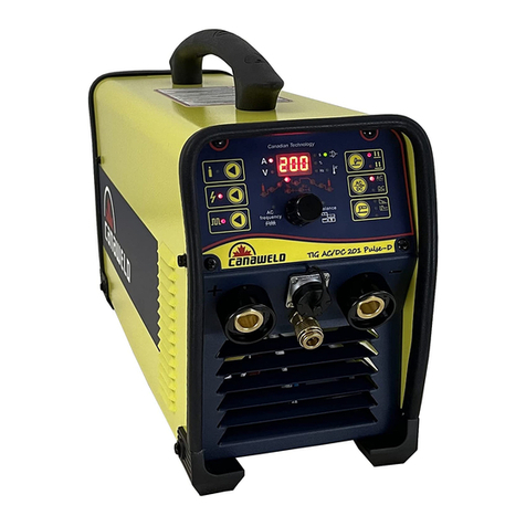
CANAWELD MMA 201 User manual

0
User Manual
Model: MMA 201

1
Thank You
From
Canaweld
Thank you for choosing a Canaweld machine, with 30+ years of welding equipment manufacturing
experience overseas, you can feel confident that you have made the right choice.
Canaweld Inc. was started in Canada to manufacture the highest quality welding and cutting
equipment for the North American market. All of our machines are electronically and weld tested
before they leave our factory to ensure the equipment you purchased is ready to work.
Our engineers are continuously working on new equipment to release new models on a regular
basis as well as to upgrade our existing line of machines. Canaweld, is in partnership with some of
the best European welding and cutting equipment manufacturers, to distribute their machines to
the North American market. Our business relationships have been created to offer our customers a
wider range of machines - only the best available for every industry.
This user manual should be read carefully to fully understand the machine you have purchased and
how to maintain it in the best operating condition.
For more information on our full line of products please visit our website or contact a dealer in
your local area, our dealer list can be found on our website –www.canaweld.com
If you require more information on how to use the equipment, please visit our website at
www.canaweld.com and view our tutorials section to find the correct one for your machine.

2
TABLE OF CONTENTS
EQUIPMENT PACKAGE
3
SECTION 1- SAFETY CAUTIONS & SYMBOLS
4-7
SECTION 2- INSTALLATION & SPECIFICATIONS
8-9
SECTION 3- OPERATION OF EQUIPMENT
10-12
SECTION 4- MAINTENANCE & BASIC TROUBLESHOOTING
13-14
SECTION 5- ELECTRICAL SPECIFICATIONS
15
SECTION 6- PARTS LIST
16-17
SECTION 7- WARRANTY & SERVICE
18-19
NOTES
20-22

3
MMA 201- WELDER PACKAGE
1
2 3 4
5 6 7
Name
Product Number
Quantity
1. Machine
PLB5180147
1
2. Work/Ground Clamp Set
ALP1980126
1
3. Electrode Holder Set
ALP2280095
1
4. TIG Torch with Gas Valve
TGE0180334
1
5. Gas Flow Regulator
TLJ1080187
1
6. Gas Hose
TLJ1080188
1
7. Machine Bag
TGJ2780145
1

4
SECTION 1- SAFETY CAUTIONS & SYMBOLS
CAUTION: READ USER MANUAL
Indicates any section that the user must read the manual to fully understand the machine’s characteristics to avoid
any hazardous situation.
ELECTRIC SHOCK
Touching live electrical parts can cause fatal shocks or severe burns. The electrode and work circuit is electrically live
whenever the output is on. The input power circuit and machine internal circuits are also live when power is on.
Do not touch live electrical parts.
Insulate yourself from work and ground using dry insulating mats or covers big enough to prevent any physical
contact with the work or ground.
Do not remove any machine covers while the machine is powered.
WELDING WORKPLACE
Be mindful of working in cramped positions, scaffolds, or any location where you can fall and become injured.
Wear a safety harness if working above floor level.
Do not work in wet areas, or while wearing wet clothing.
WELDED PARTS
Immediately after welding, all welded parts will be a very high temperature which will cause burns to any exposed
skin that makes contact.
Do not touch parts after welding. Allow for cooling period before picking up.
Allow cooling period before working on equipment.
To handle hot parts, use proper tools and/or wear heavy, insulated welding gloves and clothing to prevent
burns.

5
WELDING FUMES
Welding produces fumes and gases. Breathing these fumes and gases can be hazardous to your health.
Keep your head out of the fumes stream while welding. Do not breathe the fumes.
If inside, ventilate the area and/or use local forced ventilation at the welding point to remove welding fumes
and gases.
If ventilation is poor, wear an approved air-supplied respirator.
Read and understand the Material Safety Data Sheets (MSDSs) and the manufacturer’s instructions for metals,
consumables, coatings, cleaners, and degreasers.
Work in a confined space only if it is well ventilated, or while wearing an air-supplied respirator. Welding fumes
and gases can displace air and lower the oxygen level causing injury or death. Always have a trained
watchperson nearby.
Do not weld on coated metals, such as galvanized, lead, or cadmium plated steel, unless the coating is removed
from the weld area, the area is well ventilated, and while wearing an air-supplied respirator. The coatings and
any metals containing these elements can give off toxic fumes if welded.
WELDING RAYS
Rays from the welding process produce intense visible and invisible (ultraviolet and infrared) rays that can burn eyes
and skin.
Wear an approved welding helmet fitted with a proper shade of filter lenses to protect your face and eyes from
welding rays.
Use protective screens or barriers to protect others from flash, glare and sparks; warn others not to watch the
arc.
Wear protective clothing made from durable, flame-resistant material (leather, heavy cotton, or wool) and to
cover any exposed skin, arms, neck area.
WELDING FIRES
Welding creates heat and can lead to fires, as well certain welding forms create sparks which could also ignite
surrounding items and create a fire. The flying sparks, hot workpiece, and hot equipment can cause fires and burns.
Remove all flammables within 35 ft. (10.7 m) of the welding arc. If this is not possible, cover them with approved
covers.
Be alert that welding sparks and hot materials from welding can easily go through small cracks and openings to
adjacent areas. Be aware that welding on a ceiling, floor, bulkhead, or partition can cause fire on the hidden
side.
Watch for fire, and keep a fire extinguisher nearby.

6
GASES
Dangerous gases can be produced during welding, breathing these gases in can be hazardous to your health.
Shut off shielding gas supply when not in use.
Always ventilate confined spaces or use approved air-supplied respirator.
Do not weld in locations near degreasing, cleaning, or spraying operations. The heat and rays of the arc can react
with vapors to form highly toxic and irritating gases.
EMF- ELECTRIC MAGNETIC FIELDS
During welding, electric magnetic fields are created and can produce malfunctions in electrical components within the
area.
EMF created by welders may affect wearers of Pacemakers and other Implanted Medical Devices should keep
away.
Implanted Medical Device wearers should consult their doctor and the device manufacturer before going near
arc welding, spot welding, gouging, plasma arc cutting, or induction heating operations.
EXCESSIVE NOISE
Be mindful if your working area creates excessive noise.
Wear approved ear protection if noise level is high.
Any workers close by the area will also be effected by the noise and may also require hearing protection.
GAS CYLINDER/LINE DAMAGE
Shielding gas cylinders contain gas under high pressure. If damaged, a cylinder can explode. Since gas cylinders are
normally part of the welding process, be sure to treat them carefully.
Protect compressed gas cylinders from excessive heat, mechanical shocks, physical damage, slag, open flames,
sparks, and arcs.
Install cylinders in an upright position by securing to a stationary support or cylinder rack to prevent falling or
tipping.
Protect all gas lines from sparks, slag and open flames.
Open the cylinder valve slowly. Then slowly open regulator valve to avoid damage to the regulator.

7
ESD- ELECTRIC STATIC DISCHARGE
An electric static charge can be created during welding and discharged immediately after into any items touched by
the welder after welding.
Put on grounded wrist strap BEFORE handling boards or parts.
Use proper static-proof bags and boxes to store, move, or ship PC boards.
MOVING PARTS
A number of moving parts may be in typical welding machines such as rollers and fans.
Keep hands away from moving parts such as fans.
Keep all doors, panels, covers, and guards closed and securely in place.
Keep away from moving parts.
Keep away from pinch points such as drive rolls.
Secure any loose clothing and hair and keep away from moving parts.

8
SECTION 2- INSTALLATION, OVERVIEW & SPECIFICATIONS
INSTALLATION
ELECTRICAL
The serial number and rating information is located on the bottom of the machine. Use the rating labels to
determine input power requirements and rated output.
Check whether the voltage value variations are within the acceptable working range with a multi-meter.
(A) The input cable of the machine is ready to be plugged into a 220V compatible connector / socket or
(B) you can remove the installed plug and have the input cable “hard” wired into the appropriate building
electrical panel.
Electrical installation must meet all National and Local Codes− have only a qualified electrician do the
installation.
OVERVIEW
PRODUCT & DESIGN
Our unique electric structure and air channeling design in this series of welding machines are designed to speed
up the heat dissipation of the power device as well as improving the duty cycles of the machine.
The unique heat dissipation design leads to less damage done to the power source and control circuits from
overheating due to dust build up from air inducted by fan.
The whole machine is in form of coherent streamline, the front and rear panels are naturally integrated via
large-radian transition manner.
Front and rear panel are inset with a rubber trim on the leading edge protecting the machine from damage.
The heavy/thick steel base has an anti-rust (corrosion resistant) coating applied to extend the life of the
machine.
Heavy-duty metal casing for protection of internal components. Scratch proof coated surface for long life and
anti-corrosion durability.

9
Set of heavy duty connector and ground cable which is able to connect to other Dinse system
Heavy duty machine (150 A in 100 % duty cycle in 104 ºF 40 ºC.
FUNCTION
Hot start arc ignition application is a built –in function: allows for the arc ignition in MMA welding making
ignition easier and more reliable.
Anti-sticking function: reduce working strength in welding.
Self-adaptive arc force technology: improves the performance of the machine in long-cable welding and
enhances long-distance welding.
Advanced arc ignition by scraping: “scratch” start TIG welding without HF arc ignition circuit.
PERFORMANCE
Advanced IGBT inverter technology
Inverting frequency of 30~35 kHz greatly reduces the volume and weight of the welder.
Large reduction in magnetic and resistance loss enhances the welding efficiency resulting in energy saving.
Working frequency is beyond audio range, eliminating approximately 90% of the noise pollution.
Leading control mode
Advanced control technology allows for various welding applications and greatly improves the welding
performance in a number of welding conditions.
It can be widely used in acid and basic electrode welding.
Designed for easy arc starting, creating less spatter, stable current and good shaping properties.

10
SECTION 3- OPERATION OF EQUIPMENT
OPERATION
After being installed according to the prescribed method, and the power switch being switched on, the machine
is started with the power LED on and the fan working.
Pay attention to the polarity when making connections. An unstable arc, spatter, and electrode sticking could
happen if improper mode is selected, exchange the polarity if necessary.
STICK OPERATION
(A) Insert the electrode holder cable plug into the “+” socket on the front panel of the welding machine, and
tighten it clockwise.
(B) Insert the ground cable plug into the “-”socket on the front panel of the welding machine, and tighten it
clockwise.
Ground connection is needed for safe operation.
The connection as mentioned above is a DCEP connection. Operator can choose DCEN connection according to work
piece and electrode application requirement. Generally, DCEP connection is recommended for basic electrode, while
there is no special requirement for acid electrode.
A
B

11
Welding parameter table (for reference only)
This table is suitable for mild steel stick welding. For other materials, consult related materials and welding process for
reference.
Electrode diameter (mm)
Recommended welding current (A)
Recommended welding voltage(V)
2.0
60 - 100
22.4 - 24.0
2.5
80 - 120
23.2 - 24.8
3.2
108 - 148
23.32 - 24.92
4.0
140 - 180
24.6 - 27.2
5.0
180 - 220
27.2 - 28.8
TIG OPERATION
(A) Insert the electrode holder cable plug into the “-” socket on the front panel of the welding machine, and
tighten it clockwise.
(B) Insert the ground cable plug into the “+”socket on the front panel of the welding machine, and tighten it
clockwise.
Ground connection is needed for safe operation.
B
A

12
Control Panel
STICK Welding:
Switch Position 1
Then adjust your welding Voltage with 5.
TIG Welding:
Switch position 2
Adjust your welding current with 5.
Front Panel
1) Welding Process Switch(STICK)
2) Welding Process Switch(TIG)
3) Main voltage LED
4) Thermostatic protection LED
5) Welding current adjustment

13
SECTION 4- MAINTENANCE & BASIC TROUBLESHOOTING
MAINTENANCE
Please disconnect power to machine before performing maintenance.
Check periodically whether cable connection is in good condition (esp. plugs). Tighten any loose connections. If
there is oxidization, remove it with sandpaper and then reconnect.
Clean the dust inside the machine periodically with dry and clean compressed air. If welding environment has
heavy smoke and pollution, machine should be cleaned daily. The pressure of the compressed air should be at a
low pressure in order to avoid the small parts inside the machine being damaged.
Avoid water and vapor entering the machine. If this occurs, dry machine internals and check the insulation of
the equipment (including that between the connections and that between the connection and the enclosure).
Only when there is no moisture present, can the machine be used.
Check all cables periodically, to be sure they are in good condition with no worn spots or cracks in outer
insulation. If there is any dilapidation, rewrap it or replace all damaged cables.
Put the machine into clean packing and in a dry location if it is not to be used for an extended period of time.
If machine is in an environment that is in or near chemicals, cover machine when not in use.
Check gas hose periodically, to ensure it is in good condition and has no cracks, if any damage/wear is visible
replace hose.

14
TROUBLESHOOTING
Problem
Remedy
No welding output; unit completely inoperative;
ready light (LED) Off.
1) Be sure power cord is plugged in and that
receptacle is receiving input power.
2) Check if the Power switch is in ON
position.
3) Check and replace line fuse(s), if
necessary, or reset circuit breaker.
No welding output; ready light (LED) On.
1) Check and secure loose welding cable(s)
into receptacle(s).
2) Check for poor connection of ground
clamp to workpiece, correct if loose.
No welding output; high temperature light
(LED) On.
1) Unit overheated causing thermal
shutdown. Allow unit to cool with fan
ON.
2) Check for blocked/poor airflow to unit
and correct.
3) Reduce duty cycle or amperage.
Turn on the machine, the power LED is off, the
fan doesn't work, and no welding output.
1) No input power.
2) Check if machine is connected to power
source.
Machine is on, the fan functions, but the output
current is unstable and can't be controlled by
potentiometer when welding.
1) The current potentiometer has failed.
Replace it.
2) Check if any loose contact exists inside
the machine. If any, reconnect.
Machine is on, the power LED is on, the fan
functions, but there is no welding output.
1) Check if any loose contact exists inside
the machine.
2) Open circuit or loose contact at the joint
of output terminal.
3) The overheating LED is on.
a) The machine is under over-heating
protection status. It will reset
automatically after the welding
machine is cooled.
b) Check if the thermal switch is ok.
Replace it if damaged.
c) Check if the thermal switch has a
loose connection, and adjust it if
necessary.
The electrode holder becomes very hot during
welding.
1) The rated current of the electrode holder
is smaller than its actual working current.
Replace it with a higher rated electrode
holder.
Excessive spatter in SMAW welding.
1) The output polarity connection is
incorrect, exchange the polarity.

15
SECTION 5- ELECTRICAL SPECIFICATIONS
Machine Specifications:
Input Voltage- Single Phase
230V (+10 / -15%), 50/60Hz
Maximum effective primary current (𝐼1 𝑒𝑓𝑓 )
24 A
Maximum Primary Current
43 A
Open circuit Voltage
64 V
Output Current Range
10A - 200A
Output Voltage Range
20.4V –28V
Duty Cycle
30% @ 200A
60% @ 170A
100% @ 150A
Machine Dimensions
Length: 16 inches
Width: 6 inches
Height: 9.5 inches
Weight: 14.7 lbs.
Electrical Schematic Diagram

16
SECTION 6- PARTS LIST
Description
Component Item
MMA201 -
Quantity
Enclosures Bottom Plate
CGA2880054
1
Enclosure Cover
CGA2880097
1
Enclosure- Front Panel
CGA2880165
1
Enclosure- Rear Panel
CGA2880169
1
Cam Switch- Single Phase 32A
CGB0780066
1
CA-MC 35-70 Cable Plug (Male)
CGB0680070
1
CA-FF 35-70 Panel Socket (Female)
CGB0680064
1
Cap (Red), 20mm
CGA6280073
1
Contro Boardl PCB 200
CGC1480079
1
Electrode Holder 300 A-B
TGJ0180094
1
Fan
CGB1680098
1
Fan Plastic Holder
CGA9980350
1
Ferrite Ring 18x10x7mm
CGA1980100
2
Flat Washer (outer diameter 12mm/inner diameter 5mm)
CGA2380101
4
Front Panel Sticker
CGA6180114
1
Gland
CGA6480122
1
Ground Clamp 300 A (copper)
TGJ0580125
1
Insulation Paper- MMA 201
CGA7680137
1
Knob (Black), 20mm
CGB1880142
1
Nut (potentiometer), D=9mm
CGA2280152
1
Cage Nut
CGA2280156
1
Mother Board 200 A, 230 V
CGC9180161
1
Panel Socket (Female) CA-FF 35-70
CGB0680064
1
Plastic Holder of Package
CGA6380171
2
Rubber Elastic Strip (back)
CGA9980190
1
Rubber Elastic Strip (front)
CGA9980189
1
Rubber Feet
CGA6380191
4
Screw M10 (Hexagonal Head Bolt)
CGA2180199
1
Screw M5 (length 9mm), washer incl., new ground
CGA2180202
2
Screw, Philips 4.2mm, galvanized, total length 15mm
CGA2180210
2
Screw, Philips 5mm, (black), total length12mm
CGA2180213
8
Screw, Philips 5x15(black)
CGA2180216
4
Screw, Philips M4, (black), total length 8mm
CGA2180207
2
Strap (Belt)
CGA9980052
1

17
Rocker Switch
CGB0780236
1
Terminal, Crimping, for Welding Cable AWG 4 (8mm/25mm)
CGB0880240
1
Terminal, Double Quick
CGB0880241
1
Terminal, Fork
CGB0880242
2
Terminal, Quick (Red)
CGB0880245
3
Terminal, Quick (Yellow)
CGB0880246
1
Terminal, Ring- 1AWG16
CGB0880248
2
Thermo switch
CGB2180249
1

18
SECTION 7- WARRANTY & SERVICE
STATEMENT OF LIMITED WARRANTY:
Canaweld Inc. warrants to the end user (purchaser) of all new welding and cutting equipment, and accessories (the
“Warranted Goods”) that such Warranted Goods will be free of defects in workmanship and material. This warranty is
void if Canaweld Inc. or its Authorized Repair Centre finds that the equipment has been subjected to improper
installation, improper care or abnormal operations. THE WARRANTIES AND REMEDIES CONTAINED HEREIN ARE
EXCLUSIVE AND IN LIEU OF ALL OTHER WARRANTIES, WHETHER EXPRESS, IMPLIED OR STATUTORY, INCLUDING ANY
LIABILITY ARISING UNDER ANY WARRANTY OF MERCHANTABILITY OR FITNESS FOR A PARTICULAR PURPOSE. All
statutory warranties are excluded or limited to the maximum extent permitted by law.
WARRANTY PERIOD:
Canaweld Inc. will assume both the parts and labor expense of correcting defects during the warranty period. All
warranty periods start from the date of purchase to the original end user provided that the original invoice evidencing
the date of purchase is provided. In the event that the original invoice evidencing the date of purchase is not provided,
then the warranty period shall start on the date of delivery to the dealer. The warranty period shall extend for three (3)
years from the start of the warranty period.
CONDITIONS OF WARRANTY TO OBTAIN WARRANTY COVERAGE:
In order for any repair and/or replacement services of Warranted Goods to be covered pursuant to this warranty, such
service must be must be performed by an Authorized Repair Centre. For assistance in locating an Authorized Repair
Centre go to www.canaweld.com. Final determination of warranty on Warranted Goods will be made by Canaweld Inc.
Purchaser must present copy of a copy of the original proof of purchase, i.e. receipt/invoice, to be mailed in along with
the completed Warranty/Product Registration form.
Mail the warranty/product registration form and proof of purchase to:
Canaweld Inc.
Attn: Warranty Department
155 Drumlin Circle, Unit 1
Vaughan, Ontario, Canada L4K 3E7
WARRANTY REPAIR:
If the Authorized Repair Centre confirms the existence of a defect covered by this warranty, the defect will be corrected
by repair or replacement at Canaweld Inc.’s option. At Canaweld Inc.’s request, the Authorized Repair Centre will return
to Canaweld Inc. any equipment/accessories claimed defective under Canaweld Inc.’s warranty. By submitting
Warranted Goods to an Authorized Repair Centre, the purchaser confirms that the Authorized Repair Centre is
authorized to deliver the Warranted Goods to Canaweld Inc. Repair or replacement is the sole and exclusive remedy
available under this limited warranty.
FREIGHT COSTS:
The purchaser is responsible for shipment to and from the Authorized Repair Centre.
WARRANTY LIMITATIONS:
Canaweld Inc. will not accept responsibility or liability for
repairs made outside of an Authorized Repair Centre;
failures resulting from any improper use or installation;
failures resulting from attachments, accessory items and parts not sold or approved by Canaweld Inc.;
failures resulting from purchaser’s delay in delivering the Warranted Goods to an Authorized Repair Centre after
being notified of a potential problem with the Warranted Goods;

19
damage resulting from normal wear and tear; and
repairs or replacement of any parts reasonably considered to be consumables, including but not limited to the
following TIG torch components: (i) collet and collet body, (ii) gas nozzles, (iii) gas cups, (iv) insulators, (v) back
cups, and (vi) gas lenses, and to the following MIG/MAG torch components (vii) gas nozzles, (viii) tips, (ix) gas
lenses, (x) liners, and (xi) drive wheels.
Canaweld Inc.’s liability under this warranty shall not exceed the cost of correcting the defect of the Warranted Goods or
the cost of replacing them, whichever is less.
Canaweld Inc. will not be liable under this warranty for any loss suffered by the purchaser which:
in any manner relates to a loss of revenue, profits, opportunity or production, loss or denial of use of any
equipment or facility, increased expense of operation, economic loss, loss of goodwill or reputation, delay,
business interruption or the cost of repair to or replacement of equipment, facilities or goods and related third
party services; or
in any manner can be construed as indirect, incidental, special, punitive or consequential losses or damages;
This warranty and the rights granted herein are non-transferrable.
This warranty gives the purchaser specific legal rights. The purchaser may also have other rights which vary from country
to country.
For Purchasers in Quebec: The parties acknowledge that they have required that the present document, as well as all
documents, notices and legal proceedings entered into, given or instituted pursuant or relating directly or indirectly hereto,
be drawn up in English. Les parties reconnaissent avoir convenu que la rédaction du présente document sera en anglais,
ainsi que tous documents, avis et procedures judiciaires executés, donnés ou intents à la suite de ou en rapport,
directement ou indirectement, avec les procedures concernées.
Table of contents
Other CANAWELD Welding System manuals