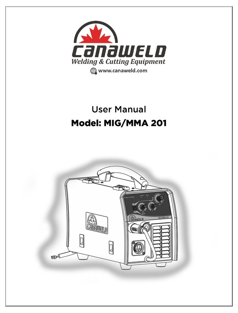
CANAWELD TIG AC DC 201 pulse D User manual

0
User Manual
Model: TIG AC DC 201 pulse D

1
Thank You
From
Canaweld
Thank you for choosing a Canaweld machine, with 30+ years of welding equipment manufacturing
experience overseas, you can feel confident that you have made the right choice.
Canaweld Inc. was started in Canada to manufacture the highest quality welding and cutting
equipment for the North American market. All of our machines are electronically and weld tested
before they leave our factory to ensure the equipment you purchased is ready to work.
Our engineers are continuously working on new equipment to release new models on a regular
basis as well as to upgrade our existing line of machines. Canaweld, is in partnership with some of
the best European welding and cutting equipment manufacturers, to distribute their machines to
the North American market. Our business relationships have been created to offer our customers a
wider range of machines - only the best available for every industry.
This user manual should be read carefully to fully understand the machine you have purchased and
how to maintain it in the best operating condition.
For more information on our full line of products please visit our website or contact a dealer in
your local area, our dealer list can be found on our website –www.canaweld.com
If you require more information on how to use the equipment, please visit our website at
www.canaweld.com and view our tutorials section to find the correct one for your machine.

2
TABLE OF CONTENTS
Contents
SECTION 1- SAFETY CAUTIONS & SYMBOLS............................................................................................................................4
SECTION 2- INSTALLATION AND OVERVIEW...........................................................................................................................8
INSTALLATION.....................................................................................................................................................................8
OVERVIEW...........................................................................................................................................................................9
SECTION 3- OPERATION OF EQUIPMENT..............................................................................................................................10
Power supply input connection ........................................................................................................................................10
POLARITY CONNECTION .........................................................................................................................................................10
Assembling the equipment (TIG) ......................................................................................................................................11
OPERATION .......................................................................................................................................................................12
Control panel.....................................................................................................................................................................13
TIG Welding Operation .....................................................................................................................................................17
TIG welding (4T operation)......................................................................................................................................17
TIG welding (2T operation) ...........................................................................................................................................18
Welding Parameters .........................................................................................................................................................20
SECTION 4- MAINTENANCE & BASIC TROUBLESHOOTING ...................................................................................................24
MAINTENANCE..................................................................................................................................................................24
BASIC TROUBLESHOOTING ...............................................................................................................................................24
SECTION 5- ELECTRICAL SPECIFICATIONS .............................................................................................................................27
SPECIFICATIONS ................................................................................................................................................................27
Electrical schematic diagram ............................................................................................................................................28
SECTION 6- WARRANTY & SERVICE.......................................................................................................................................29

3
TIG AC/DC 201 Pulse D - WELDER PACKAGE
1
2 3 4
5 6 7
Name
Product Number
Quantity
1. Machine
PLB2380148
1
2. Work/Ground Clamp Set
ALP198449
1
3. Electrode Holder Set
ALP2280095
1
4. TIG Torch –Electronic 12 ft
CW-SG26FX-1K-12SL-GS4
1
5. Gas Flow Regulator
LV150
1
6. Gas Hose
TLJ1080188
1
7. Machine Bag
TGJ2780145
1

4
SECTION 1- SAFETY CAUTIONS & SYMBOLS
CAUTION: READ USER MANUAL
Indicates any section that the user must read the manual to fully understand the machine’s characteristics to avoid
any hazardous situation.
ELECTRIC SHOCK
Touching live electrical parts can cause fatal shocks or severe burns. The electrode and work circuit is electrically live
whenever the output is on. The input power circuit and machine internal circuits are also live when power is on.
•Do not touch live electrical parts.
•Insulate yourself from work and ground using dry insulating mats or covers big enough to prevent any physical
contact with the work or ground.
•Do not remove any machine covers while the machine is powered.
WELDING WORKPLACE
Be mindful of working in cramped positions, scaffolds, or any location where you can fall and become injured.
•Wear a safety harness if working above floor level.
•Do not work in wet areas, or while wearing wet clothing.
WELDED PARTS
Immediately after welding, all welded parts will be a very high temperature which will cause burns to any exposed
skin that makes contact.
•Do not touch parts after welding. Allow for cooling period before picking up.
•Allow cooling period before working on equipment.
•To handle hot parts, use proper tools and/or wear heavy, insulated welding gloves and clothing to prevent
burns.

5
WELDING FUMES
Welding produces fumes and gases. Breathing these fumes and gases can be hazardous to your health.
•Keep your head out of the fumes stream while welding. Do not breathe the fumes.
•If inside, ventilate the area and/or use local forced ventilation at the welding point to remove welding fumes
and gases.
•If ventilation is poor, wear an approved air-supplied respirator.
•Read and understand the Material Safety Data Sheets (MSDSs) and the manufacturer’s instructions for metals,
consumables, coatings, cleaners, and degreasers.
•Work in a confined space only if it is well ventilated, or while wearing an air-supplied respirator. Welding fumes
and gases can displace air and lower the oxygen level causing injury or death. Always have a trained
watchperson nearby.
•Do not weld on coated metals, such as galvanized, lead, or cadmium plated steel, unless the coating is removed
from the weld area, the area is well ventilated, and while wearing an air-supplied respirator. The coatings and
any metals containing these elements can give off toxic fumes if welded.
WELDING RAYS
Rays from the welding process produce intense visible and invisible (ultraviolet and infrared) rays that can burn eyes
and skin.
•Wear an approved welding helmet fitted with a proper shade of filter lenses to protect your face and eyes from
welding rays.
Use protective screens or barriers to protect others from flash, glare and sparks; warn others not to watch the
arc.
•Wear protective clothing made from durable, flame-resistant material (leather, heavy cotton, or wool) and to
cover any exposed skin, arms, neck area.
WELDING FIRES
Welding creates heat and can lead to fires, as well certain welding forms create sparks which could also ignite
surrounding items and create a fire. The flying sparks, hot workpiece, and hot equipment can cause fires and burns.
•Remove all flammables within 35 ft. (10.7 m) of the welding arc. If this is not possible, cover them with approved
covers.
•Be alert that welding sparks and hot materials from welding can easily go through small cracks and openings to
adjacent areas. Be aware that welding on a ceiling, floor, bulkhead, or partition can cause fire on the hidden
side.
•Watch for fire, and keep a fire extinguisher nearby.

6
GASES
Dangerous gases can be produced during welding, breathing these gases in can be hazardous to your health.
•Shut off shielding gas supply when not in use.
•Always ventilate confined spaces or use approved air-supplied respirator.
•Do not weld in locations near degreasing, cleaning, or spraying operations. The heat and rays of the arc can react
with vapors to form highly toxic and irritating gases.
EMF- ELECTRIC MAGNETIC FIELDS
During welding, electric magnetic fields are created and can produce malfunctions in electrical components within the
area.
•EMF created by welders may affect wearers of Pacemakers and other Implanted Medical Devices should keep
away.
•Implanted Medical Device wearers should consult their doctor and the device manufacturer before going near
arc welding, spot welding, gouging, plasma arc cutting, or induction heating operations.
EXCESSIVE NOISE
Be mindful if your working area creates excessive noise.
•Wear approved ear protection if noise level is high.
•Any workers close by the area will also be effected by the noise and may also require hearing protection.
GAS CYLINDER/LINE DAMAGE
Shielding gas cylinders contain gas under high pressure. If damaged, a cylinder can explode. Since gas cylinders are
normally part of the welding process, be sure to treat them carefully.
•Protect compressed gas cylinders from excessive heat, mechanical shocks, physical damage, slag, open flames,
sparks, and arcs.
•Install cylinders in an upright position by securing to a stationary support or cylinder rack to prevent falling or
tipping.
•Protect all gas lines from sparks, slag and open flames.
•Make sure to open the cylinder valve carefully and then open the regulator valve in order to protect the
regulator from any possible damage.
•Open the cylinder valve slowly. Then slowly open regulator valve to avoid damage to the regulator.

7
ESD- ELECTRIC STATIC DISCHARGE
An electric static charge can be created during welding and discharged immediately after into any items touched by
the welder after welding.
•Put on grounded wrist strap BEFORE handling boards or parts.
•Use proper static-proof bags and boxes to store, move, or ship PC boards.
MOVING PARTS
A number of moving parts may be in typical welding machines such as rollers and fans.
•Keep hands away from moving parts such as fans.
•Keep all doors, panels, covers, and guards closed and securely in place.
•Keep away from moving parts.
•Keep away from pinch points such as drive rolls.
•Secure any loose clothing and hair and keep away from moving parts.

8
SECTION 2- INSTALLATION AND OVERVIEW
INSTALLATION
ELECTRICAL
•The serial number and rating information is located on the bottom of the machine. Use the rating labels to
determine input power requirements and rated output.
•Check whether the voltage value variations are within the acceptable working range with a multi-meter.
•(A) The input cable of the machine is ready to be plugged into a 230 V 10%
−
+compatible connector / socket or
(B) you can remove the installed plug and have the input cable “hard” wired into the appropriate building
electrical panel.
•(C) The machine is designed to operate on a 120V %10
−
+voltage, a compatible connector can be fitted to the
input cable (D) or it can be hard wired into the electrical panel.
•Electrical installation must meet all national and Local Codes− has only a qualified electrician does the
installation.
Please note (in the 120v setting): This welder is a
very powerful machine. It is strongly
recommended to the user to have a separate 30
(A) electrical circuit wired to the welder location
by a certified electrician.

9
OVERVIEW
PRODUCT &DESIGN
The working principle of TIG AC DC 201 pulse D welding machines is shown as the following figure. single-phase
110/220V work frequency AC is rectified into DC (about 380V), then is converted to medium frequency AC (about 44K
Hz) by inverter device (IGBT module), after reducing voltage by medium transformer (the main transformer) and
rectifying by medium frequency rectifier (fast recovery diodes), then is outputted DC or AC by selecting IGBT module.
The circuit adopts current feedback control technology to insure current output stably. Meanwhile, the welding current
parameter can be adjusted continuously and stepless to meet with the requirements of welding craft.
TIG AC DC 201 pulse D welding machine adopts the latest pulse width modulation (PWM) technology and insulated
gate bipolar transistor (IGBT) power module, which can change work frequency to medium frequency so as to replace
the traditional hulking work frequency transformer with the cabinet medium frequency transformer. Thus, it is
characterized with portable, small size, light weight, low consumption and etc.
FUNCTION
➢MCU control system , responds immediately to any changes.
➢The newest PFC technology , power factor more than 0.98
➢High frequency and high voltage for arc igniting to ensure the success ratio of igniting arc, the reverse polarity
ignition ensures good ignition behavior in TIG-AC welding.
➢Avoid AC arc-break with special means, even if arc-break occurs the HF will keep the arc stable.
➢TIG/DC operation,If the tungesten electrode touches the workpiece when welding, the current will drop to short-
circuit current to protect tungsten.
➢Intelligent protection: over-voltage, over-current, over-heat, when the problems listed before occurred, the alarm
lamp on the front panel will be on and the output current will be cut off. It can self-protect and prolong the using
life.
➢Double purposes: AC inverter TIG/MMA and DC inverter TIG/MMA, Excellent performance on Al-alloy, carbon steel
stainless steel ,titanium.
According to choosing the front panel functions, the following six welding ways can be realized.
⚫DC MMA
⚫DC TIG
⚫AC MMA
⚫AC TIG

10
SECTION 3- OPERATION OF EQUIPMENT
Power supply input connection
TIG AC DC 201 pulse D welding machines’power supply connects to single-phase 95- 270V
When the power supply voltage is over the safe work voltage, there are over voltage and under voltage protection
inside the welder, the alarm light will on, at the same time, the current output will be cut off.
If the power supply voltage continually goes beyond the safe work voltage range, it will shorten the welder life-
span. The below measures can be used:
⚫Change the power supply input net. Such as, connect the welder with the stable power supply voltage of distributor;
⚫Induce the machines using power supply in the same time;
⚫Set the voltage stabilization device in the front of power cable input.
POLARITY CONNECTION (STICK PROCESS)
MMA (DC): Choosing the connection of DCEN or DCEP according to the different electrodes. Please refer to the
electrode manual.
MMA (AC): No requirements for polarity connection.

11
Assembling the equipment (TIG)
⚫Workpiece is connected to the positive electrode of welding machine, and welding torch is connected to the negative
electrode, which is called DC POSITIVE CONNECTION; otherwise, that is called DC NEGATIVE CONNECTION. Generally,
it is usually operated in DC POSITIVE CONNECTION in TIG welding mode.
⚫The control cable of torch switch consists of 2 wires, pedal control of 3 wires and the aero socket has 14 leads.
⚫Consumable parts for TIG torch, such as tungsten electrode、tip、gas nozzle、electrode shield(short/long) , please
enquire us by mail or phone according to the accessory codes.
⚫When WSE-200PFC welding machine is operated in HF ignition method, the ignition spark can cause interferences in
equipment near the welding machine. Be sure to take specially safety precautions or shielding measures.

12
OPERATION
1Negative output negative polarity output.
2gas connector Is connected to the gas input pipe of torch.
3Aero socket Is connected to torch switch control wire.(It has 9 leads and lead 1- lead 2 are connected to torch
switch control wire).
4Positive output positive polarity output.
5Shield gas input joint To connect one head of the gas hose while the other head of which is connected to argon gas
cylinder.
6Power source switch Switch to “ON”, the welder is turned on, while switch to “OFF”, the welder is turned off.
7Power source input To connect power source.
8Fan When the electric welding machine is over-heat, the fan operates. It is used for cooling the components and
parts inside the welder

13
Control panel
Overview
The key feature of the control panel is the logical way in which the controls are arranged. All the main parameters
needed for day-to-day working can easily be
-selected with the keys
-altered with the adjusting dial
-shown on the display during welding.
The illustration below shows an overview of the main settings needed for day-to-day working, using the TIG AC DC 201
pulse D control panel as an example. You will find a detailed description of these settings in the following section.
(1) AC/DC selecting key

14
(2) Mode selecting key
(3) Power/ Alarm indicator
Light up if the power switch on
Light up If the welder overheat, over-voltage or over-current. At the same time, display Err 001.
(4) Welding current adjust
Before the start of welding, you can use this potentiometer adjust welding current
(5) Welding current display
Display the pre-set or the actual welding current value.
Before the start of welding, it shows the pre-set current value
After the start of welding, it shows the present actual value of the welding current.
(6) Adjusting dial
If the parameter indicator lights up, then the selected parameter can be altered on adjusting dial.
Available parameters where 2T and 4T mode have been selected:
Gas pre-flow time
Unit S
Setting range 0.1—10
Factory setting 0.3

15
Starting current (only with 4T)
Unit A
Setting range 5—100%of main current (DC);10—100%of main current (AC)
Factory setting 5
Upslope time
Unit S
Setting range 0—10
Factory setting 0
Welding current
Unit A
TIG AC DC 201 pulse D 5—200 (DC);10—200 (AC)
Base current
Unit A
TIG AC DC 201 pulse D 5—200 (DC);10—200 (AC)
Important! Only selectable when “pulse key”has been pressed.
Ratio of pulse duration to base current duration
Unit %
Setting range 5—100
Factory setting 5
Important! Only selectable when “pulse key”has been pressed.
Pulse frequency
Unit Hz
Setting range 0.5—200
Factory setting 0.5
Important! Only selectable when “pulse key”has been pressed.

16
Downslope time
Unit S
Setting range 0—10
Factory setting 0
Crater arc current (only with 4T)
Unit S
Setting range 5—100% of main current Iw (DC);10—100% of main current Iw (AC)
Factory setting 5
Gas post-flow time
Unit S
Setting range 1—10.0
Factory setting 3
AC frequency (only with TIG-AC)
Unit Hz
Setting range 50—250 (Iw<70A)
50—200 ( 70A≤Iw<100A)
50—150 (100A≤Iw<140A)
50—120 (140A≤Iw<170A)
50—100 (170A≤Iw)
Balance (only with TIG-AC)
Balance adjustment is mainly used to set the adjustment of eliminating metal-oxide (such as Aluminum, Magnesium and
its alloy) while AC output.
Unit %
Setting range 15—50
Factory setting 15
(7) Rod electrode(MMA) welding key

17
Parameter Setting range
Arc force 0-10
Hot start 0-10
Arc length 0-10
TIG Welding Operation
TIG welding (4T operation)
The start current and crater current can be pre-set. This function can compensate the possible crater that
appears at the beginning and end of the welding. Thus, 4T is suitable for the welding of medium thickness plates.
Pulsed TIG long welding(4T):
t( s)
0
I( A)
Loosen the
switch
t1 t5 t7
Striking success
Stop arc
t3 t4
Base current setting
value
t2 t6
Loosen the
switch
Repress down the
switch
Start
current Crater
current
Welding current (peak
current) setting value
Press and hold the
welding gun switch
Introduction:
⚫0:Press and hold the gun switch, Electromagnetic gas valve is turned on. The shielding gas starts to flow;
⚫0~t1:Pre flow time, adjustment range of pre flow time :0.1~10.0S;
⚫t1:Striking success, adjustment range of start current: 5~200A;
⚫t2:Loosen the gun switch, the output current slopes up from start current; if the output pulse function is turned on,
the output current is pulsed;
⚫t2~t3:Output current slopes up to the setting current value; adjustment range of up slope time 0~10.0S ;
⚫t3~t4:Welding process. During this period, the gun switch is loosened;
Note: If the output pulse function is turned on, the output current is pulsed. If the output pulse function is turned
off, the output current is DC current;
⚫t4:Repress down the gun switch, the output current slopes down to crater current; if the output pulse function is
turned on, the slope down current is pulsed;
⚫t4~t5:Down slope time, adjustment rang of down slope time: 0~10.0S;
⚫t5~t6:Crater current holds time; adjustment range of crater current: 5~200A;
⚫t6:Loosen the gun switch, stop arc, and keep on argon flowing;

18
⚫t6~t7:Post flow time, adjustment range of post flow time: 1.0~10.0S;
⚫t7:Electromagnetic valve is closed and stop argon flowing. Welding is finished.
Remarks: Repeat welding function:
In 4T mode, when you press the second time to stop the arc, if your press in a very short time, the
output current will reduce to half firstly, then the customer can weld in small current as you want without
ignite again, if you press the trigger again for stop the arc; But if press in more than 0.5 seconds, the arc will
stop at your second press.
TIG welding (2T operation)
This function without the adjustment of start current and crater current is suitable for the Re-tack welding、
transient welding、thin plate welding and so on.
Pulsed TIG short welding(2T):
t( s)
0
I( A)
Loosen the
welding gun
switch
Press and hold the
welding gun switch
t1 t5
Striking
success Stop arc
t3 t4
Base current setting
value
t2
Welding current (peak
current) setting value
5A
Introduction:
⚫0:Press and hold the gun switch, Electromagnetic gas valve is turned on. The shielding gas starts to flow;
⚫0~t1:Pre flow time, adjustment range of pre flow time :0.1~10.0S;
⚫t1~t2:Striking success, the output current slopes up to the setting current from minimum current(5A); if the output
pulse function is turned on, the slope up current is pulsed;
⚫t2~t3:During the whole welding process, the gun switch is pressed and held without releasing;
Note: If the output pulse function is turned on, the output current is pulsed. If the output pulse function is turned
off, the output current is DC current;
⚫t3:Loosen the gun switch, the output current slopes down; if the output pulse function is turned on, the slope down
current is pulsed;
⚫t3~t4:The output current slopes down to minimum current (5A), stop arc; adjustment range of down slope time:
0~10S;
⚫t4~t5:Post flow time, adjustment range of post flow time: 0.1~10.0S;
⚫t5:Electromagnetic valve is closed and stop argon flowing. Welding is finished.

19
Short circuit protect function:
○
1TIG /DC/LIFT :If the tungesten electrode touches the workpiece when welding, the current will drop to 20A, which
can reduce the tungsten spoilage farthestly,prolong the using life of the tungsten electrode,and prevent tungsten
clipping.
○
2TIG /DC/HF :If the tungesten electrode touches the workpiece when welding, the current will drop to 0 within 1s,
which can reduce the tungsten spoilage farthestly,prolong the using life of the tungsten electrode,and prevent
tungsten clipping.
○
3MMA operation:if the electrode touches workpiece over two seconds, the welding current will drop to the 0
automatically to protect the electrode.
Prevent arc-break function :TIG operation,Avoid arc-break with special means, even if arc-break occurs the HF will
keep the arc stable
④TIG :If the TIG torch is pressed quickly, the welding current will drop a half, then if the TIG torch is pressed quickly
again, the welding current will get back.
Notices:
⚫Check the condition of welding and connection units firstly, otherwise there will be malfunction such as ignition
spark gas leakage out of control and so on.
⚫Check that whether there is enough Argon gas in the shield gas cylinder, you can test the electromagnetic gas valve
through the switch on the front panel.
⚫Do not let the torch aim at your hand or else of your body. When you press the torch switch, the arc is ignited with
a high-frequency, high-voltage spark, and the ignition spark can cause interferences in equipment.
⚫The flow rate is set according to the welding power used in the job. Turn the regulation screw to adjust the gas flow
which is shown on the gas hose pressure meter or the gas bottle pressure meter.
⚫The spark ignition works better if you keep the 3mm distance from the workpiece to the tungsten electrode during
the ignition.
Note: When select AC output, the current and the wave form are as same as the above, but output polarity
changes alternately.
This manual suits for next models
1
Table of contents
Other CANAWELD Welding System manuals
Popular Welding System manuals by other brands

STAMOS
STAMOS WELDING TABLE user manual

Würth
Würth WIG 180 DC Translation of the original operating instructions

Lincoln Electric
Lincoln Electric WELD-PAK 155 Operator's manual

Timco Tools
Timco Tools P160MMA manual

Lincoln Electric
Lincoln Electric RANGER 250 GXT (AU) Operator's manual

Migatronic
Migatronic AUTOMIG PULSE Series user guide