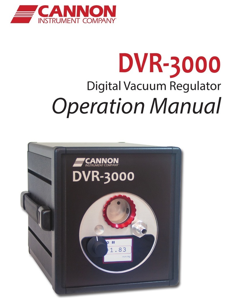
Cannon DVR-1000 Installation instructions manual

Instruction & Operation Manual
P/N 41.2990
DVRDVR
Digital Vacuum Regulator


i
Contents | Cannon Instrument Company®
Copyright
Copyright ©2021 CANNON Instrument Company®. All rights reserved.
Trademarks
CANNON® and the CANNON® logo are registered trademarks of Cannon Instrument Company®.
Meriam® is a registered trademark of Meriam®
Contact
Address: CANNON Instrument Company®
2139 High Tech Road
State College PA 16803, USA
Phone: 1-814-353-8000; 1-800-676-6232
Fax: 1-814-353-8007
Website: www.cannoninstrument.com
Email:
Sales: sales@cannoninstrument.com
Service: service@cannoninstrument.com
Manual P/N 41.2990

Cannon Instrument Company® | Contents
i
Contents
Contents............................................................................................................................i
Safety Precautions............................................................................................................ iv
Notes/Cautions/Warnings .............................................................................................................v
DVR Overview ................................................................................................................... 1
DVR Function ................................................................................................................................1
DVR Application............................................................................................................................1
DVR-1000 vs. DVR-1500 ............................................................................................................2
Configuration Options...............................................................................................................2
Specifications.................................................................................................................... 3
Tubing Connections ...........................................................................................................4
DVR-1000 Connections .................................................................................................................4
Connect to your Application......................................................................................................4
DVR-1500 Connections .................................................................................................................5
Vacuum Trap.................................................................................................................................5
Electrical Connections...................................................................................................................5
Connecting Power Cable...........................................................................................................6
DVR Operation .................................................................................................................. 7
Default Settings ............................................................................................................................7
Accessories ...............................................................................................................................7
Turning ON the DVR .....................................................................................................................7
Meter Display/Key Control Options...............................................................................................8
Adjusting the Flow Rate ............................................................................................................8
Bleeding Vacuum ......................................................................................................................9
Adjusting Offset............................................................................................................................9
Adjust HI/LO Set Points...............................................................................................................10
ALAr........................................................................................................................................10
Selecting Set Point Values .......................................................................................................... 11
DVR Cleaning & Maintenance ........................................................................................... 12
Cleaning ......................................................................................................................................12
Maintenance ...............................................................................................................................12
Troubleshooting the DVR............................................................................................................12
Vacuum System Leak..............................................................................................................12
Altering Factory Settings.................................................................................................. 13
Changing the Engineering Unit of Measure................................................................................. 13
Changing Engineering Units.................................................................................................... 13

ii
| DVR Operation Manual
Adjusting Control Set Points ................................................................................................... 13
Adjustment Procedure: Adjusting the Control Set Points (SET 1 and SET 2) ........................... 14
Selecting Set Point Values .......................................................................................................... 15
Replacement Parts........................................................................................................... 16
Warranty ........................................................................................................................ 17
Products Limited Warranty ......................................................................................................... 17
Reagent and Chemical Warranty................................................................................................. 17
Returning a Product to CANNON................................................................................................ 17
Required Information..............................................................................................................18
Hazardous Materials ...............................................................................................................18
Shipping Notification ..............................................................................................................18
Appendix A – Calibrating the SETRA Gauge ....................................................................... 19
Calibration Options .....................................................................................................................19
Calibration Procedure .............................................................................................................19
Removing the Differential Gauge from the DVR......................................................................19
Reassembling the DVR................................................................................................................20
Appendix B - Calibrating the Meriam Gauge ....................................................................... 21
Front Panel Lockout....................................................................................................................21
Determining Lockout Status ...................................................................................................21
Engaging Front Panel Lockout ................................................................................................21
Disabling Lockout ...................................................................................................................22
Changing the Lockout Code....................................................................................................23
Calibration Options .....................................................................................................................23
Zeroing the Gauge ..................................................................................................................24
Removing the Differential Gauge from the DVR..........................................................................24
Reassembling the DVR............................................................................................................25
Gauge Display Errors...................................................................................................................25
Setting User Units.......................................................................................................................26
Procedure ...............................................................................................................................27
List of Figures
Figure 1: DVR with CT-1000 Constant Temperature Bath .................................................................1
Figure 2: CANNON DVR in Horizontal & Vertical Positions ...............................................................2
Figure 3: NPT Port Connection..........................................................................................................4
Figure 4: DVR Front Panel Connections ............................................................................................4
Figure 5: 3VM Vacuum Manifold .......................................................................................................7
Figure 6: RUN Position on DVR Front Panel ......................................................................................8
Figure 7: OFFSET Keys ......................................................................................................................9
Figure 8: HOLD/mode Key ................................................................................................................9

Cannon Instrument Company® | Contents
iii
Figure 9: SCAN/adj Key...................................................................................................................10
Figure 10: SCAN/adj Key .................................................................................................................10
Figure 11: HOLD/mode Key.............................................................................................................10
Figure 12: Meriam Display...............................................................................................................21
Figure 13: Meriam Display with Vacuum .........................................................................................26
List of Tables
Table 1: DVR Specifications..............................................................................................................3
Table 2: Engineering Units .............................................................................................................. 13
Table 3: DVR Replacement Parts.....................................................................................................16
Table 4: Gauge Display Errors .........................................................................................................25
Table 5: User Units..........................................................................................................................26

iv
|DVR Operation Manual
Safety Precautions
Always observe these signs and instructions. Observe cautionary messages and warnings in order to
protect yourself and prevent others from physical injury or property damage.
CANNON advises turning OFF the vacuum source when changing DVR meter settings. For the DVR-1000,
it is necessary to disconnect the connection to the in-house vacuum source or turn the vacuum off. For
the DVR-1500 unit, which includes a built-in vacuum pump, the vacuum can be shut off by switching the
DVR front panel switch to the METER position. Turning off the vacuum prevents vacuum from building
up while altering the meter gauge settings.
•Only qualified personnel should operate DVR.
•Read and understand all operating instructions and safety precautions listed in this manual before
installing or operating the instrument. Contact Cannon Instrument Company with questions
regarding instrument operation or documentation.
•Do not deviate from the installation, operation, or maintenance procedures described in this
manual. Improper use of the DVR may result in a hazardous situation and may void the
manufacturer’s warranty.
•Handle and transport the unit with care. Sudden jolts or impacts may cause damage to
components.
•Position the instrument on a sturdy table or workbench.
•Provide at least 15 cm (6”) of ventilation space for the rear of the unit.
•Do not turn the power switch on and off rapidly and repeatedly.
•Observe all warning labels. Never remove warning labels.
•Never operate damaged or leaking equipment.
•Unless procedures specify otherwise, always turn off the unit and disconnect the MAINS cable
from the power source before performing service or maintenance procedures, accessing the
electronics drawer, or before moving the unit.
•Never operate the equipment with damaged MAINS power cables.
•Refer all service and repairs to qualified personnel.
Warning: Always ensure the protective ground (earth) terminals of the
instrument connect to a protective conductor of the MAINS power cord.
Use only the manufacturer-supplied power cord, and do not use an
extension cord without protective grounding.

Cannon Instrument Company® | Safety Precautions
v
Notes/Cautions/Warnings
Keep this manual near the instrument to easily access necessary information while operating or
preparing CMRV measurement.
Notes, cautions, and warnings are used in the manual to call an operator’s attention to important details
prior to performing a procedure or step. Read and follow these important instructions. Failure to
observe these instructions may void warranties, compromise operator safety, and/or result in damage
to the instrument.
Notes provide more information about the content that follows.
Cautions alert the operator to conditions that may damage equipment.
Warnings alert the operator to conditions that may cause injury.
It is prohibited to copy or reproduce in part or in whole this manual without authorization bycopyright.
If any part in this manual is not clear to understand or is missing articles, contact your local dealer or
sales representative.
Manufacturer is not liable for any loss or damage directly or indirectly caused by use of the instrument
or its consequences.
This manual pertains directly to the DVR Digital Vacuum Regulator. For details relating to other
accessories or equipment, please refer to the appropriate manufacturer-supplied documentation.

vi
|DVR Operation Manual

1
|DVR Operation Manual
DVR Overview
This manual provides the necessary information for proper installation, operation, and maintenance of
the CANNON DVR 1000 Series Digital Vacuum Regulator.
DVR Function
The CANNON DVR 1000 Series instrument is designed to regulate vacuum at 300 mm Hg below
atmospheric pressure. Vacuum may be adjusted to other settings, from 28 mm Hg to 411 mm Hg. The
DVR is suitable for use with all CANNON temperature baths, including the CT and TE Series high and low
temperature baths.
Figure 1: DVR with CT-1000 Constant Temperature Bath
DVR Application
The DVR is ideal for use with the Cannon-Manning calibrated CMVC series viscometers, the Modified
Koppers Calibrated MKVC Series viscometers, and the Asphalt Institute Vacuum Calibrated AIVC series C
Series viscometers, and the Asphalt Institute Vacuum Calibrated AIVC series viscometers for
measurement of highly viscous materials such as asphalt cement at 60 °C (140 °F) per ASTM D2171
specifications. Both the Cannon-Manning and the Modified Koppers permit viscosity measurement from

2
| DVR Operation Manual
42 to 200,000 poise. The Asphalt Institute AIVC Series 400R and 800R viscometers, also available from
CANNON, extend that range to 1,400,000 poise and 5,800,000 poise, respectively.
The DVR is also useful in other laboratory systems where accurate measurement and control of vacuum
from 28 to 330 mm Hg below atmospheric pressure is required.
DVR-1000 vs. DVR-1500
The DVR-1000 is designed to regulate a laboratory’s in-house vacuum system.
The DVR-1500 includes an internal vacuum pump and does not require in-house vacuum.
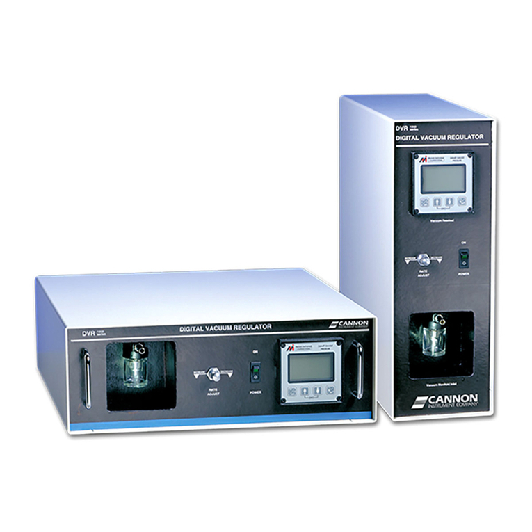
Configuration Options
The DVR is available from CANNON in both horizontal and vertical configurations. With its sturdy steel
construction, the horizontal DVR unit is able to support any CANNON CT or TE Series temperature bath.
The vertical or horizontal configuration offers convenience in locations where workspace is at a
premium.
Figure 2: CANNON DVR in Horizontal & Vertical Positions

Cannon Instrument Company® | Specifications
3
Specifications
Table 1: DVR Specifications
Specifications
Details
Model
DVR-1000 and DVR-1500 Digital Vacuum Regulator
Methodology
ASTM D2171
Applications
Common applications include asphalt cement and asphalt
binders, with an operational range of 28 mm Hg to 410 mm
Hg below atmospheric pressure
Dimensions (W × D × H)
Horizontal:47 cm × 45.8 cm × 17.2 cm
(18.5 in × 18 in × 6.75 in)
Vertical:17.2 cm × 45.8 cm × 17.2 cm
(6.75 in × 18.5 in × 18 in)
Weight
20 kg (45 lb)
Shipping Weight
29.5 kg (65 lb)
Vacuum Range & Accuracy
28 mm Hg to 410 mm Hg below atmospheric pressure ± 0.5
mm Hg* NIST certified and traceable
*comes preset to 300 mm Hg below atmospheric pressure
Maximum Vacuum (if user-
supplied)
560 ± 50 mm Hg below atmospheric pressure
Minimum Vacuum (if user-
supplied)
320 ± 50 mm Hg below atmospheric pressure
Safety Limit
746 mm Hg below atmospheric pressure
Operating Conditions
15 °C to 30 °C, 10% to 75% relative humidity (non-
condensing), Installation Category II, Pollution Degree 2
Electrical Specifications
110 VAC, 50/60 Hz; 115 VAC, 50/60 Hz; 230 VAC, 50/60 Hz
400 W power consumption (unit) 1100 W power
consumption (AWHE)
Compliance
CE Mark: EMC Directive (2004/108/EC); Low Voltage
Directive (2006/95/EC); HI-POT (1900 VDC, 60 sec.); ROHS

4
| DVR Operation Manual
Tubing Connections
Tubing connections for the DVR vary depending on the specific model. Follow the instructions
appropriate for your unit. Make sure that there is adequate slack in the tubing to avoid kinks in the line,
which prevents optimal control.
DVR-1000 Connections
Ensure that the vacuum source meets the specifications listed in the Specifications section (a vacuum
regulator may be required). To connect the DVR-1000 to your in-house vacuum, secure the tubing to the
1/8” NPT PORT connection on the DVR rear panel using an appropriate fitting (not supplied). Refer to
Figure 3.
Figure 3: NPT Port Connection
Connect to your Application
Connect the DVR-1000 to your vacuum manifold or application using the 4' length of ¼“ x 5/8" O.D.
rubber vacuum tubing provided by CANNON. Secure the tubing to the Vacuum Manifold Inlet on the
front panel of the DVR. Refer to Figure 4. Push the tubing firmly into place over the barbed nipple fitting.
Attach the other end of the tube to your manifold/application, clamping the connection if necessary.
Check all vacuum connections to make sure they are secure.
Figure 4: DVR Front Panel Connections

Cannon Instrument Company® | Tubing Connections
5
DVR-1500 Connections
The DVR-1500, although it has its own internal vacuum pump, uses the identical front panel connection
as shown in Figure 4. Connect the DVR-1500 to your vacuum manifold or application using the 4' length
of ¼” x 5/8" O.D. rubber vacuum tubing provided by CANNON. Secure the tubing to the Vacuum
Manifold Inlet on the front panel of the DVR. Push the tubing firmly into place over the barbed nipple
fitting. Attach the other end of the tube to your manifold/application, clamping the connection if
necessary.
Check the vacuum connections to make sure they are secure.
The PORT connection on the rear of the DRV-1500 (see Figure 3) is an exhaust port for the vacuum. On
this model, use the CANNON-supplied muffler to seal the port. Screw the muffler onto the PORT
connection, and finger-tighten the muffler.
Vacuum Trap
The glass bottle vacuum trap at the front of the DVR is designed to prevent liquids from being pulled
into the system and damaging the internal components. The trap can only “catch” about two ounces of
fluid; it is not suitable for use as a reservoir or waste receptacle. In the event that a small amount of
fluid does enter the vacuum system, immediately power OFF the unit and empty the glass bottle. You
may also wish to clean the 10’ rubber tubing with appropriate solvent(s). Thoroughly dry the tubing
before reconnecting it to the DVR.
Electrical Connections
After vacuum tubing is successfully connected, use the MAINS power cord provided with the DVR to
supply electricity to the unit.
The ~MAINS symbol indicates instructions or connections for the AC power supply. The AC Power input
must match the electrical specifications listed on the label on the rear panel of the instrument. The
supplied AC MAINS power cord must attach to the connector labelled ~MAINS. This connection serves as
a means of disconnect and should be readily accessible.
Caution: Avoid pulling liquid solvent past the vacuum trap as this may cause
internal damage to DVR components and create a safety hazard.
Caution: When supplying power to the instrument, connect the protective
ground (earth) terminals of the instrument to the protective conductor of the
CANNON-supplied MAINS power cord. The main plug for the power cord should
only be inserted in a socket outlet or receptacle provided with a protective
ground (earth) contact. Do NOT use an extension cord/power cable without a
protective conductor (grounding).

6
| DVR Operation Manual
The (O) symbol indicates the OFF position for the electrical switches for the unit (AC Mains or
accessories).
Connecting Power Cable
Make sure that the 3-position switch on the front panel is set to the center STANDBY position.1.
Plug the power cord into the DVR rear panel IEC Power Inlet connector.2.
Plug the other end of the cord into an appropriate electrical outlet.3.

Cannon Instrument Company® | DVR Operation
7
DVR Operation
Default Settings
The DVR is designed to display and regulate vacuum for viscometry applications per ASTM D2171
specifications. The DVR regulates vacuum using points preset at CANNON for efficient regulation of
vacuum at 300 mm Hg below atmospheric pressure.
To adjust the control settings to regulate at other pressures, refer to section Adjust HI/LO Set Points.
Accessories
TheThe DVR is designed for use in conjunction with the CANNON 3VM and 4VM vacuum manifolds. The
3VM manifold (part number 9726-V10) has three valves and pairs with the CANNON CT-500 Series
Constant Temperature Bath. The 4VM manifold (part number 9726-V05) has four valves and pairs with
the CANNON CT-1000 Series and CT-2000 Series Constant Temperature Baths.
Figure 5: 3VM Vacuum Manifold
Turning ON the DVR
Make sure the instrument power cord is connected to an appropriate power source. Electrical1.
requirements are specified on the rear panel of the DVR unit.
Ensure that all vacuum connections are secure.2.
Toggle the POWER switch on the DVR front panel to the RUN position (see Figure 6). The gauge LCD3.
is activated and the solenoid valves “click” open. On DVR-1500 models, the internal vacuum pump
engages.

8
| DVR Operation Manual
Figure 6: RUN Position on DVR Front Panel
Meter Display/Key Control Options
Adjusting the Flow Rate
Solenoid Regulators
The DVR’s vacuum is regulated by two solenoid valves mounted inside the unit. The valves operate in
tandem to maintain consistent vacuum at the desired setting. CANNON creates preset control set points
for the solenoid valves to regulate vacuum at 300 mm Hg below atmospheric pressure. If it is necessary
to adjust these settings, see section Altering Factory Settings.
Rate Adjust Knob
Solenoid valve efficiency is influenced by the rate of flow in the DVR vacuum/pressure valve system. The
flow rate is regulated with an internal needle valve. This valve is manually adjusted on the DVR front
panel using the RATE ADJUST knob.
Recovery/Overshoot
The flow rate also affects the recovery time (the amount of time required to restore desired vacuum
settings when a significant change has occurred) and the amount of overshoot (the degree of vacuum
change in excess of the desired reading observed before the vacuum stabilizes at the desired setting).
Using the RATE ADJUST Knob
Set the RATE ADJUST knob so that the instrument attains the desired setting as quickly as possible
without overshooting the control target by more than 0.5 mm Hg. Turn the knob clockwise to decrease
the flow rate, or counterclockwise to increase the flow rate.
Limiting Overshoot
For example, if you are controlling at 300 mm Hg, increase the flow rate until the overshoot produces a
gauge reading greater than 300.5 mm Hg. Then reduce the flow rate until the overshoot drops to less
than 0.5 mm Hg. Check the new setting by opening and closing switches on the vacuum manifold,
causing a drop in vacuum. Then observe the recovery time and overshoot.

Cannon Instrument Company® | DVR Operation
9
Caution: It is impossible to completely close the needle valve controlled by the
RATE ADJUST knob. Do not try to force the valve closed using to the RATE ADJUST
knob, or damage may occur to the valve components.
Note: For the needle valve to function efficiently, the solenoid SET 2 value must
be higher than the solenoid SET 1 value (see Chapter 5)XXXX
Bleeding Vacuum
If the DVR instrument will not be used for a while, toggle the front panel switch to the center STANDBY
position. This action disengages solenoid operation for both models and turns off the DVR-1500 vacuum
pump.
CANNON advises users bleed off residual DVR system vacuum to 250 mm or lower when the instrument
is in the center STANDBY position. This prevents the unit from overshooting the target vacuum (default
300 mm Hg) when the toggle switch is returned to the RUN position.
Adjusting Offset
The OFFSET command allows the user to adjust the reading relative to a known value. To set the
OFFSET, follow the procedure outlined below.
Press and hold the SCAN/adj and HOLD/mode keys for eight seconds, then release. The display1.
alternates between cal and noYes for ten seconds. Refer to Figure 7.
Figure 7: OFFSET Keys
To specify yes and select CH1, press and hold the HOLD/mode key to display CH1.2.
Press the HOLD/mode key to display ALAr. Refer to Figure 8.3.
Figure 8: HOLD/mode Key

10
| DVR Operation Manual
Press the SCAN/adj key to display OFFST. Refer to Figure 9.4.
Figure 9: SCAN/adj Key
Press the HOLD/mode key to display the number 0.5.
Set the desired value for the meter to display at the presently applied pressure.6.
a. Press the SCAN/adj key to move the numbers up (+).
b. Press the HOLD/mode key to move the numbers down (-).
c. Upon reaching the desired number, press the SCAN/adj and HOLD/mode keys at the same
time. The number flashes repeatedly. Then, press the SCAN/adj key to readjust the number or
the HOLD/mode key to accept it. After the number is accepted, the meter will display BUSY for
10 seconds, and then resume normal operation.
Adjust HI/LO Set Points
Note: The HI/LO Set Points are used as control set points.
ALAr
The ALAr command allows you to set high and low pressure alarm points. The HI or LO indicator light is
lit if the applied pressure exceeds the set values. The alarm output signals are available at the terminal
strip. To set the HI and LO, use the following procedure outlined below.
Press and hold the SCAN/adj and HOLD/mode keys for eight seconds, then release; the display then1.
alternates between cal and noYes for ten seconds.
Figure 10: SCAN/adj Key
To specify yes and select CH1, press and hold the HOLD/mode key to display CH1.2.
Figure 11: HOLD/mode Key

Cannon Instrument Company® | DVR Operation
11
Press the HOLD/mode key to display ALAr.3.
Press the HOLD/mode key to display the present value of the Low Alarm point.4.
Set the LO ALARM Point. The decimal point that was set during calibration (CAL_U, CAL_C) will5.
display.
a. Press the SCAN/adj key to move the numbers up (+).
b. Press the HOLD/mode key to move the numbers down (-).
c. Upon reaching the desired number, press the SCAN/adj and HOLD/mode keys at the same time.
The number then flashes repeatedly. Then, press the SCAN/adj key to readjust the number, or
the HOLD/mode key to accept it.
Repeat the same procedure as in Step 5 to set the HI ALARM Point. After the number is accepted6.
the DATUM 2000 control panel resumes normal operation.
Selecting Set Point Values
Control set points for the DVR have been determined empirically. Selecting new set points to control at
a different level of vacuum or at a different unit of measurement, involves some trial and error.
Once your control point (desired vacuum setting) is known, you must select and test new set points.
Normal factory set points may provide a useful reference. The unit is shipped from CANNON with a
value of 292.5 mm Hg for LO and a value of 299.6 mm Hg for HI.These settings allow the DVR to control
at 300 mm Hg ± the tolerance factor of 0.5 mm Hg.
Mechanically, the DVR is plumbed so that the solenoid controlled by the Lo register allows air to bypass
the Rate Adjust valve. This feature makes it possible to achieve a vacuum very close to the desired value
in a very short time. For the HI solenoid, the vacuum source routs through the Rate Adjust valve,
permitting a finer adjustment. For accurate control, both set points and the Rate Adjust valve must be
set properly.
Remember that the Rate Adjust valve setting varies depending on the values chosen for the solenoid set
points. When resetting the control points, ensure you also check/adjust the Rate Adjust knob.
This manual suits for next models
1
Table of contents
Other Cannon Controllers manuals
Popular Controllers manuals by other brands

Allied
Allied Chemetron 4000 Series Operation & maintenance manual

Omron
Omron CS1G/H-CPUxx-EV1 Programming manual

YASKAWA
YASKAWA MP900 Series user manual

Ariston
Ariston Chaffoteaux Elco RVS 63 operating instructions

Twinkly Pro
Twinkly Pro TWPRO1000ETHP user guide

Siemens
Siemens GBB 2 Series Mounting instructions