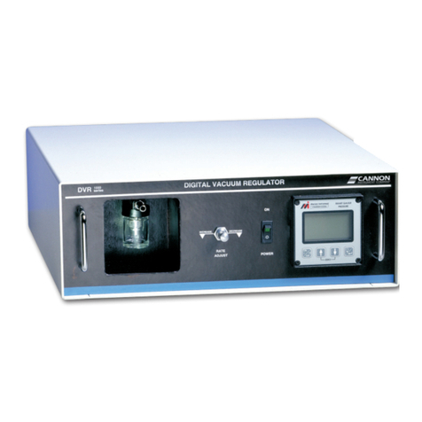
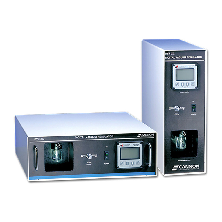
Cannon DVR-3000 User manual

Operation Manual
Digital Vacuum Regulator
DVR-3000

Copyright
Copyright ©2023 CANNON Instrument Company®. All rights reserved.
Trademarks
CANNON® and the CANNON logo are registered trademarks of Cannon Instrument Company®.
Contact
Address: CANNON Instrument Company®
2139 High Tech Road
State College PA 16803, USA
Phone: 1-814-353-8000; 1-800-676-6232
Fax: 1-814-353-8007
Website: www.cannoninstrument.com
Email:
Sales: sales@cannoninstrument.com
Service: service@cannoninstrument.com
Manual P/N: 41.3041

Cannon Instrument Company® | Contents
i
DVR-3000 Operation Manual
Contents
Contents............................................................................................................................i
DVR Overview ................................................................................................................... 1
DVR Function ................................................................................................................................1
DVR Application............................................................................................................................1
Specifications................................................................................................................................2
Notes/Cautions/Warnings .............................................................................................................2
Safety Precautions ........................................................................................................................3
DVR Setup ........................................................................................................................4
Unpack and Inspect.......................................................................................................................4
Tubing Connections ......................................................................................................................4
Connect to your Application..........................................................................................................4
Vacuum Trap.................................................................................................................................5
Electrical Connections...................................................................................................................5
Connecting Power Cable...........................................................................................................6
DVR Operation .................................................................................................................. 7
Default Settings ............................................................................................................................7
Accessories ...................................................................................................................................7
Turning ON the DVR .....................................................................................................................7
Adjusting the Flow Rate ................................................................................................................7
DVR Cleaning & Maintenance .............................................................................................8
Cleaning ........................................................................................................................................8
Maintenance .................................................................................................................................8
Troubleshooting the DVR..............................................................................................................8
Vacuum System Leak....................................................................................................................8
Controls operation.............................................................................................................9
Setup Option.................................................................................................................................9
Pause Pumping Motor...................................................................................................................9
Adjusting Set Point .......................................................................................................................9
Software update.............................................................................................................. 11
Replacement Parts........................................................................................................... 18
Warranty ........................................................................................................................ 19
Products Limited Warranty .........................................................................................................19
Reagent and Chemical Warranty.................................................................................................19
Returning a Product to CANNON................................................................................................19
Required Information..............................................................................................................20

ii
Cannon Instrument Company®| DVR-3000 Operation Manual
Hazardous Materials ...............................................................................................................20
Shipping Notification ..............................................................................................................20
Appendix A – Calibrating the pressure sensor ..................................................................... 21
Calibration Options .....................................................................................................................21
Calibration Procedure .................................................................................................................21
List of Figures
Figure 1: DVR-3000 ...........................................................................................................................1
Figure 2: DVR Front Panel Connections ............................................................................................5
Figure 3: Rear View of Unit................................................................................................................6
Figure 4: 3VM Vacuum Manifold .......................................................................................................7
Figure 5: Setup Option Selection ......................................................................................................9
Figure 6: Pause Pumping Selection...................................................................................................9
Figure 7: Set Point Adjustment Selection..........................................................................................9
Figure 8: Open Unit......................................................................................................................... 11
Figure 9: App on App Store (Apple).................................................................................................12
Figure 10: App on Google Play (Android).........................................................................................12
Figure 11: Select Gear ..................................................................................................................... 13
Figure 12: Settings Menu ................................................................................................................ 13
Figure 13: Wi-Fi Setting Screen ....................................................................................................... 13
Figure 14: Configure App Screen.....................................................................................................14
Figure 15: Connect to Wi-Fi in ESPTouch ........................................................................................14
Figure 16: ESPTouch IP Address Display ......................................................................................... 15
Figure 17: DVR Network Information .............................................................................................. 15
Figure 18: Choose a File Webpage...................................................................................................16
Figure 19: Drag and Drop .bin File for Upload..................................................................................16
Figure 20: Unsuccessful Upload Error Message............................................................................... 17
List of Tables
Table 1: DVR Specifications ..............................................................................................................2
Table 2: Packing List (Main Components) .........................................................................................4
Table 3: DVR Replacement Parts.....................................................................................................18

Cannon Instrument Company® | DVR Overview
1
DVR-3000 Operation Manual
DVR Overview
This manual provides the necessary information for proper installation, operation, and maintenance of
the CANNON DVR-3000 Digital Vacuum Regulator.
DVR Function
The CANNON DVR-3000 instrument is designed to regulate vacuum at 300 mm Hg below atmospheric
pressure, at flow rates of up to 3 LPM. Vacuum may be adjusted to other settings, from 95–450 mm Hg.
The DVR is suitable for use with all CANNON temperature baths, including the CT and TE Series high and
low temperature baths.
Figure 1: DVR-3000
DVR Application
The DVR is ideal for use with Cannon-Manning calibrated CMVC series viscometers, Modified Koppers
Calibrated MKVC Series viscometers, Asphalt Institute Vacuum Calibrated AIVC series C Series
viscometers, and Asphalt Institute Vacuum Calibrated AIVC series viscometers for measurement of
highly viscous materials such as asphalt cement at 60 °C (140 °F) per ASTM D2171 specifications. Both
Cannon-Manning and Modified Koppers permit viscosity measurement from 42 to 200,000 poise.
Asphalt Institute AIVC Series 400R and 800R viscometers, also available from CANNON, extend that
range to 1,400,000 poise and 5,800,000 poise, respectively.
The DVR is also useful in other laboratory systems where accurate measurement and control of vacuum
from 95–450 mm Hg below atmospheric pressure is required.

2
Cannon Instrument Company®| DVR-3000 Operation Manual
Specifications
Table 1: DVR Specifications
Specifications
Details
Model
DVR-3000
Methodology
ASTM D2171
Applications
Common applications include asphalt cement and asphalt
binders, with an operational range of 95–450 mm Hg below
atmospheric pressure
Dimensions (W × D × H)
16.8 cm x 25.0 cm x 18.5 cm (6.62" x 10" x 7.25")
Weight
5 kg (11 lb)
Shipping Weight
6.8 kg (115 lb)
Vacuum Range &
Accuracy
95–450 mm Hg below atmospheric pressure ± 0.5 mm Hg
(Factory preset to 300 mm Hg below atmospheric pressure)
NIST certified and traceable
Safety Limit
746 mm Hg below atmospheric pressure
Operating Conditions
15 °C to 30 °C, 10% to 75% relative humidity (non-condensing),
Installation Category II, Pollution Degree 2
Electrical Specifications
120 VAC, 50/60 Hz; 240 VAC, 50/60 Hz; 175 watts power
consumption
Compliance
CE Mark: EMC Directive (2004/108/EC); Low Voltage Directive
(2006/95/EC); HI-POT (1900 VDC, 60 sec.); ROHS
Notes/Cautions/Warnings
Notes, cautions, and warnings are used in the manual to call an operator’s attention to important details
prior to performing a procedure or step. Read and follow these important instructions. Failure to
observe these instructions may void warranties, compromise operator safety, and/or result in damage
to the instrument.
Notes: Provides more information about the content that follows.
Cautions: Alerts the operator to conditions that may damage equipment.
Warnings: Alerts the operator to conditions that may cause injury.

Cannon Instrument Company® | DVR Overview
3
If any part in this manual is not clear to understand or is missing articles, contact your local dealer or
sales representative.
The manufacturer is not liable for any loss or damage directly or indirectly caused by use of the
instrument or its consequences.
This manual pertains directly to the DVR-3000 Digital Vacuum Regulator. For details relating to other
accessories or equipment, please refer to the appropriate manufacturer-supplied documentation.
Safety Precautions
Always observe the following general safety precautions for proper and safe operation of the DVR-3000.
•Only qualified personnel should operate the DVR.
•Read and understand all operating instructions and safety precautions listed in this manual before
installing or operating the instrument. Contact Cannon Instrument Company with questions
regarding instrument operation or documentation.
•Do not deviate from the installation, operation, or maintenance procedures described in this
manual. Improper use of the DVR may result in a hazardous situation and may void the
manufacturer’s warranty.
•Handle and transport the unit with care. Sudden jolts or impacts may cause damage to
components.
•Position the instrument on a sturdy table or workbench.
•Provide at least 15 cm (6”) of ventilation space for the rear of the unit.
•Do not turn the power switch on and off rapidly and repeatedly.
•Observe all warning labels. Never remove warning labels.
•Never operate damaged or leaking equipment.
•Unless procedures specify otherwise, always turn off the unit and disconnect the MAINS cable
from the power source before performing service or maintenance procedures, accessing the
electronics drawer, or before moving the unit.
•Never operate the equipment with damaged MAINS power cables.
•Refer all service and repairs to qualified personnel.
Warning: Always ensure the protective ground (earth) terminals of the
instrument connect to a protective conductor of the MAINS
power cord. Use only the manufacturer-supplied power cord,
and do not use an extension cord without protective grounding.

Cannon Instrument Company® | DVR Setup
4
DVR-3000 Operation Manual
DVR Setup
Unpack and Inspect
Unpack and inspect DVR and all accessories as soon as they are received. Refer to the Packing List to
verify all materials are present. See Table 2.
Table 2: Packing List (Main Components)
Quantity
Description
Part Number
1
DVR-3000
9726-T70
1
MAINS AC Power Cable
Varies by locale
1
Tubing, 4' (122 cm) 5/16" ID x 5/8" OD Neoprene
42.9
1
CE Note
N/A
1
Manual
41.3041
Tubing Connections
Tubing connections for the DVR-3000 may be arranged in a variety of ways to suit application and
environment. Make sure that there is adequate slack in the tubing to avoid kinks in the line (kinks
prevent optimal control).
Connect to Your Application
DVR-3000 features an international standard G1/8 parallel port on the front of the unit. A simple push fit
can be made with a rubber hose; alternatives may be fitted by simply unscrewing the fitting.
1. Connect the DVR-3000 to your vacuum manifold or application using the 4' (122 cm) length
rubber vacuum tubing provided by CANNON. Secure the tubing to the Vacuum Manifold Inlet on
the front panel of the DVR. Refer to Figure 2.
2. Push the tubing firmly into place over the barbed nipple fitting.
3. Attach the other end of the tube to your manifold/application, clamping the connection if
necessary.
4. Check all vacuum connections to make sure they are secure.

Cannon Instrument Company® | DVR Setup
5
Figure 2: DVR Front Panel Connections
Vacuum Trap
An integral vacuum trap is provided on the front of the DVR-3000 and is designed to prevent liquids
from being pulled into the system and damaging the internal components.
The trap can only “catch” about 20 mL of fluid; it is not suitable for use as a reservoir or waste
receptacle. In the event a small amount of fluid enters the vacuum system, perform the following:
1. Immediately power OFF the unit.
2. Unscrew the hand-tight ring on the front to empty the chamber.
3. Clean the connecting rubber tubing with appropriate solvent(s).
4. Thoroughly dry the tubing before reconnecting it to the DVR.
Electrical Connections
After vacuum tubing is successfully connected, use the MAINS power cord provided with the DVR to
supply electricity to the unit.
Caution: Avoid pulling liquid solvent past the vacuum trap as this may cause
internal damage to DVR components and create a safety hazard.
Caution: The main plug for the power cord should only be inserted in a socket
outlet or receptacle provided with a protective ground (earth) contact.
Do NOT use an extension cord/power cable without a protective
conductor (grounding).
Control knob
Vacuum tray
Display
Vacuum inlet port (G 1/8)

6
Cannon Instrument Company®| DVR-3000 Operation Manual
The ~MAINS symbol indicates instructions or connections for the AC power supply. The AC Power input
must match the electrical specifications listed on the label on the rear panel of the instrument. The
supplied AC MAINS power cord must attach to the connector labelled ~MAINS. This connection serves as
a means of disconnect and should be readily accessible.
The (O) symbol indicates the OFF position for the electrical switches for the unit (AC Mains or
accessories).
Connecting Power Cable
1. Plug the power cord into the DVR rear panel IEC Power Inlet connector. See Figure 3.
2. Plug the other end of the cord into an appropriate electrical outlet.
Figure 3: Rear View of Unit

Cannon Instrument Company® | DVR Operation
7
DVR-3000 Operation Manual
DVR Operation
Default Settings
The DVR is designed to display and regulate vacuum for viscometry applications per ASTM D2171
specifications. The DVR regulates vacuum for efficient regulation of vacuum at 300 mm Hg below
atmospheric pressure.
To adjust the control settings to regulate other pressures, refer to section Adjusting Set Point.
Accessories
The DVR is designed for use in conjunction with the CANNON 3VM and 4VM vacuum manifolds. The
3VM manifold (part number 9726-V10), see Figure 4, has three valves and pairs with the CANNON
CT-500 Series Constant Temperature Bath. The 4VM manifold (part number 9726-V05) has four valves
and pairs with the CANNON CT-1000 Series and CT-2000 Series Constant Temperature Baths.
Figure 4: 3VM Vacuum Manifold
Turning ON the DVR
1. Make sure the instrument power cord is connected to an appropriate power source. Electrical
requirements are specified on the rear panel of the DVR unit.
2. Ensure that all vacuum connections are secure.
3. Switch the POWER switch on the DVR rear panel to the ON position. This action activates the
display and turns on the internal vacuum pump. Factory default is set at 300 mm Hg; to adjust,
see section Controls operation.
Adjusting the Flow Rate
It is not necessary to adjust the flow rate manually. The DVR-3000 incorporates automatic internal
regulation which compensates for demanded flow quickly and accurately.

Cannon Instrument Company® | DVR Cleaning & Maintenance
8
DVR-3000 Operation Manual
DVR Cleaning & Maintenance
Cleaning
Caution: Before cleaning the DVR, turn off the instrument and unplug the MAINS
power cord. Do NOT clean the instrument while it is in operation.
Best practices dictate that it is ideal to periodically clean the outside of the unit with a cloth moistened
with water and/or a mild detergent solution. Do not allow water or detergent solution to drip into the
unit.
1. Wipe down the front panel, sides and top.
2. Remove the vacuum trap cover and wipe out the vacuum trap enclosure.
3. If there is oil or residue in the glass jar, use an appropriate solvent and drying agent to clean
the jar.
4. Replace vacuum trap cover. The unit is inoperable unless the vacuum trap is in place.
In the event of completely overcoming the trap, it is possible to remove an internal cover and clean the
insides of the DVR mechanism. Only authorized personnel are permitted to perform this procedure.
Maintenance
Do not allow oil to accumulate in the vacuum trap. Remove the cover, empty, and clean as often as
necessary. Remove MAINS power from the instrument BEFORE removing the vacuum trap.
Periodically inspect the line cord for fraying and/or exposed wiring. When removing the cord from the
power outlet, pull it out with the plug. Do not pull the cord.
Troubleshooting the DVR
Upon discovery of a problem with the DVR, first make sure that all tubing and electrical connections are
correct and secure, and that the power switch is in the correct ON position.
Vacuum System Leak
If the vacuum system is leaking, check the vacuum trap cover to ensure it is tightly screwed into
position.

Cannon Instrument Company® | Controls operation
9
DVR-3000 Operation Manual
Controls operation
The DVR unit offers user adjustable options. Use the control knob (see Figure 2) to move the cursor
around the screen. The control knob can be rotated left and right. The red highlighting box will move
over the options for the instrument. Then press the control knob, to select option.
Setup Option
Select the gear icon to access the update function. Press the knob to enter the option. See Figure 5.
Figure 5: Setup Option Selection
Pause Pumping Motor
Select the pause button (see Figure 6) to stop the motor but allow the high precision pressure sensor to
continue to read. Press the control knob to turn OFF the pump. Keep it highlighted and press it again to
turn it back on. This function is particularly useful for locating system leaks.
Figure 6: Pause Pumping Selection
Adjusting Set Point
1. For small adjustments of setpoint, rotate the knob to put the highlighting red box around the
indicated pressure; see Figure 7.
Figure 7: Set Point Adjustment Selection

10
Cannon Instrument Company®| DVR-3000 Operation Manual
2. Press again, to select the setpoint.
3. Twist the control knob left or right, to change the pressure in 1 mm increments. If a big change
is required, press the control knob again to highlight the right most digit; press again to highlight
the next digit, etc. At each step, the highlighted digit is changed by twisting the control knob left
or right.
4. On completion, press the control knob once, to set the new point.

Cannon Instrument Company® | Software update
11
DVR-3000 Operation Manual
Software update
A potentially useful function, available since the introduction of the new, high-performance DVR-3000, is
the availability of an over-the-air software update (OTA). In normal use, the OTA function is carefully
hidden so it cannot be accidentally enabled. To use OTA, it will be necessary to open the unit to allow
radio energy from a smartphone into the case.
1. Open the unit.
a. Remove the four screws on the back panel.
b. Pull off the two plastic trims over the rear panel.
c. Slide out the metal top of the box, leaving enough room for radio to get into the
electronics. See Figure 8.
Figure 8: Open Unit
Note: Some tubing
removed for clarity

Cannon Instrument Company® | Software update
13
3. On unit, rotate the control knob to highlight the gear and press knob to select. See Figure 11.
Figure 11: Select Gear
4. When the Settings window opens, rotate the control knob to highlight Wi-Fi and press the
control knob to select. See Figure 12.
Figure 12: Settings Menu
5. When Wi-Fi window opens, rotate the control knob to highlight Connect Ap and press knob to
select. See Figure 13.
Figure 13: Wi-Fi Setting Screen

14
Cannon Instrument Company®| DVR-3000 Operation Manual
6. When message to configure app appears, choose Cancel as this was completed in steps 2--5. See
Figure 14.
Figure 14: Configure App Screen
7. In the ESPTOUCH app, your phone needs to be connected to the same Wi-Fi Network you intend
to use on the DVR. Input the Wi-Fi password and hit Confirm. See Figure 15.
Figure 15: Connect to Wi-Fi in ESPTouch
Enter Wi-Fi
password
Press Confirm

Cannon Instrument Company® | Software update
15
8. When the connection is successful, the ESPTouch app will display IP address. Take note of this IP
address for Step 10. Note: This address may change every time a new connection is established.
See Figure 16.
Figure 16: ESPTouch IP Address Display
9. At the same time, the DVR Screen will automatically refresh and display the network
information (Access point name, IP address, etc.). The items on this screen can be highlighted by
turning the knob. See Figure 17.
Figure 17: DVR Network Information
10. On a PC connected to the same Wi-Fi network as the DVR, open a web browser and type in the
DVR’s IP Address in the following format: https://IPAddress (example: https://192.168.50.236).
Note IP Address
Access Point Name
IP Address

16
Cannon Instrument Company®| DVR-3000 Operation Manual
11. The Choose a File webpage will appear, see Figure 18. If it does not, verify you have typed
“https://” before the IP Address from your DRV (Step 9).
Figure 18: Choose a File Webpage
12. If software update is available, CANNON instrument Company will send the user a binary file
that can be uploaded on this screen. Drag and drop the .bin file, then click Upload. See
Figure 19.
Figure 19: Drag and Drop .bin File for Upload
13. The Screen will state Uploading. If the upload is successful, the DVR will automatically restart,
and the main screen will appear.
Table of contents
Other Cannon Controllers manuals
Popular Controllers manuals by other brands

Siemens
Siemens SIRIUS 3RA2120 Series operating instructions

Datapath
Datapath Aetria WallControl VSN Series quick start guide

Rocky Mountain
Rocky Mountain 1-PIN instructions

Honeywell
Honeywell PRESSURETROL L404F Product data

Bosch
Bosch Rexroth OptiFeed-FS EcoDrive 03 FLP04VRS Functional description

Daikin
Daikin MicroTech II Installation and maintenance manual