manuals.online logo
Brands
  1. Home
  2. •
  3. Brands
  4. •
  5. Cannon
  6. •
  7. Indoor Fireplace
  8. •
  9. Cannon Canterburry User manual

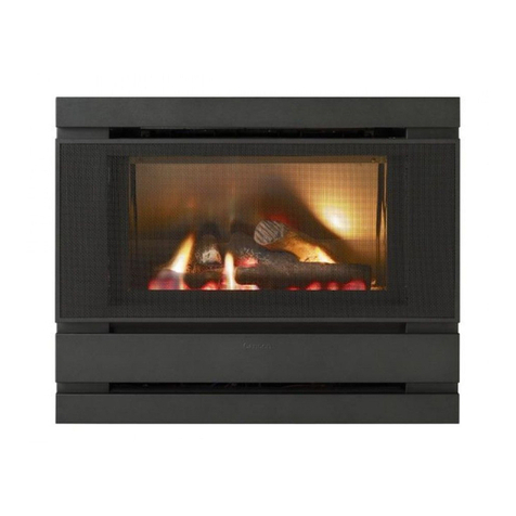
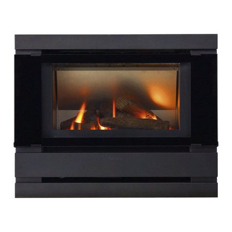
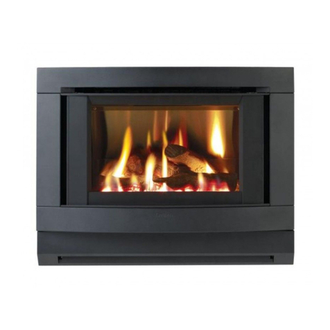
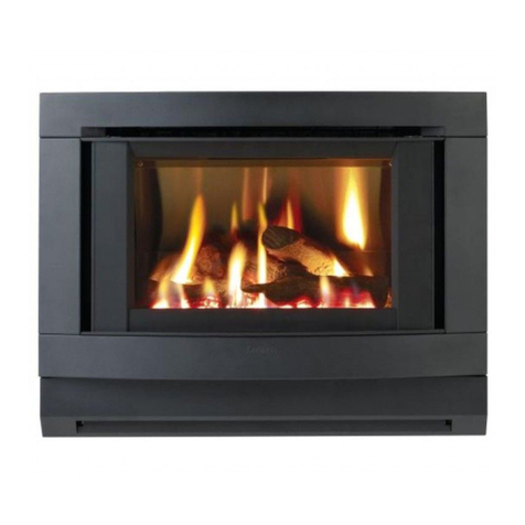
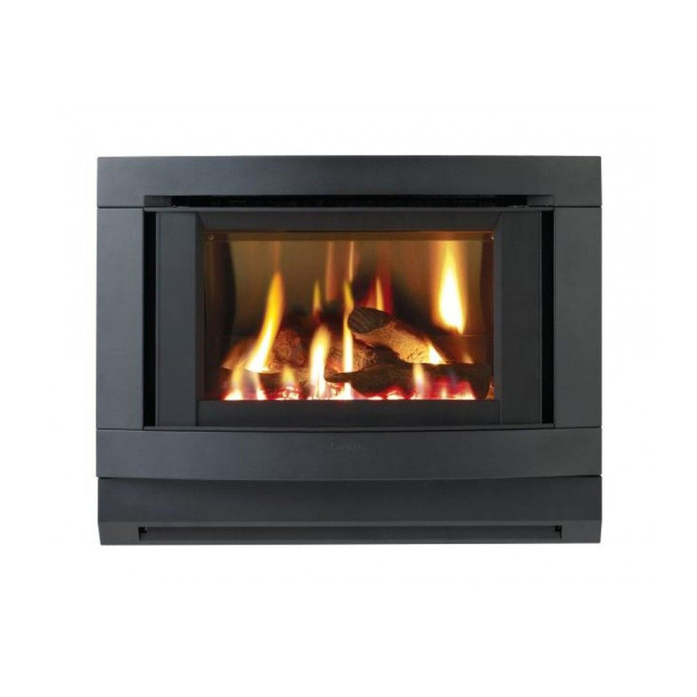
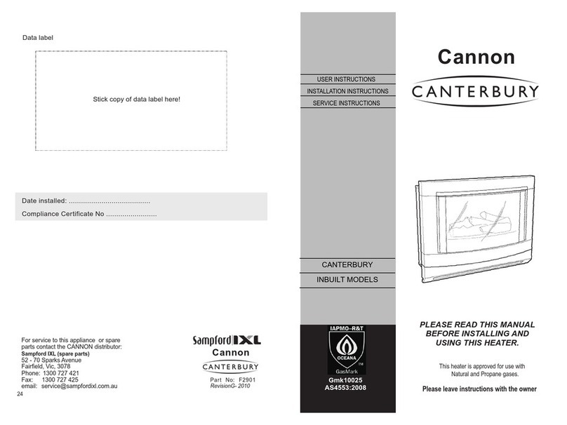
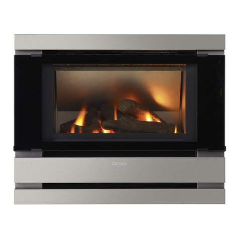
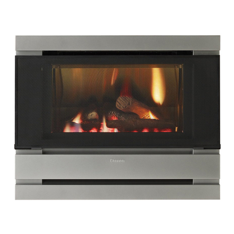
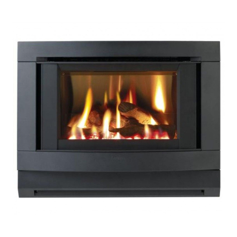
Cannon Canterburry User manual

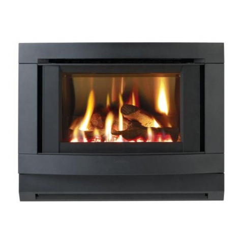
CANTERBURY
INBUILT MODELS
INSTALLATION
Part No: F2663
Revision J -March 2010
Cannon
Cannon
This heater is approved for use with
Read these instructions in conjunction
Gmk10025
AS4553:2008 Natural or Propane gases.
INSTALLATION INSTRUCTIONS
FOR FITMENT INTO A
COMBUSTIBLE ENCLOSURE
TO SUIT MOCK FIREPLACE
INSTALLATIONS
with heater installation instructions
MOCK FIREPLACE
INSTRUCTIONS
CONTENTS
ITEM PAGE.
Page 9.
Pag
General
e 1
P
Mock fireplace enclosure recommendations
age 2
Mock cavity dimensions - Canterbury
age 3
P
Overall dimensions of heater cabinet Page 4
Fitment of spacer brackets and blanket Page 5
Installation into wall cavity - MOCKKITRA Method A Page 6 & 7
P
Installation into combustible cavity - MOCKKITRO
Method B
age 8 & 9
INSTALLATION ADVICE OR TECHNICAL ISSUES
SAMPFORD IXL
ON
PH: 1300 727 421
or
FAX: 1300 727 425
CONTACT:
INSTALLATION INTO A COMBUSTIBLE ENCLOSURE
MOCKKITRO ( SINGLE SKIN FLUE ) METHOD B
METHOD.
125
25 MIN FROM
COMBUSTIBLES
FLUE
SPIGOT
FLUE SPIGOT
MOUNTING
BRACKET
SUPPORT
BRACKETS
100mm
FLUE
562 TO C
L
TO SUIT FLUE SYSTEM
AND ENCLOSURE
TO SUIT FLUE SYSTEM
AND ENCLOSURE DEPTH
DEPTH OF
HEATER 300
1. Mark out vertical centre-line of flue outlet on rear of enclosure.
2. Mark out horizontal centre-line of heater flue outlet on rear of
enclosure utilise support brackets to support flue spigot mounting
bracket.
3. Measure distance required to engage flue outlet to flue spigot
once installed. Tighten adjustment screws as required.
INSTALL BLANKET
GENERAL
Page 1.
INSTALLATION INTO A COMBUSTIBLE ENCLOSURE
MOCKKITRO ( SINGLE SKIN FLUE ) METHOD B
Page 8.
FIG 7.
600 mm BETWEEN
TOP OF COWL AND
NEAREST PART OF ROOF FLUE COWL
APPROVED
TO AG604
FLUE CLAMP
FLASHING
ROOF CLADDING
RE
AFT RS
PROVIDE
CLEARANCE
AROUND
CEILING JOISTS
MOCK ENCLOSURE
TO NORMAL
BUILDING PRACTICE
MAINTAIN 25mm
CLEARANCE
FROM ALL
COMBUSTIBLES
INSULATION BLANKET
HEATER
100 mm DIA
SINGLE SKIN
FLUE
FIT TWO LENGTHS OF
VERTICAL FLUE (1.8 M)
BEFORE FITTING ANY
BENDS. IF BENDS ARE
USED, FIT INSIDE OF
FLUE PIPE.
USE NO MORE THAN
TWO BENDS IN THE
TOTAL FLUE RUN AND
MAINTAIN AT LEAST
250 mm OF STRAIGHT
FLUE PIPE BETWEEN
THE BENDS.
125
505 MAX
MAKE SURE THERE IS ADEQUATE VENTILATION IN ROOM.
FLUSH WITH INNER
ENCLOSURE
FLUE OUTLET
TO FIT INSIDE OF
FLUE SPIGOT
FLUE TO BE
SUPPORTED
INDEPENDENTLY
OF THE APPLIANCE
FLUE CONNECTION.
This heater shall only be installed by an authorised person. This
appliance shall be installed in accordance with the
manufacturers installation instructions.
Australian Standard 5601, municipal building codes, electrical
wiring regulations and any other statutory regulations must be
adhered to.
To conform with the gas space heater approval requirements
the spacers must be permanently fitted to maintain the required
clearance from combustible materials.
These instructions are to be read in conjunction with the heater
installation booklet.
The heater must be installed correctly to provide safe and
reliable operation.
Please take the time to read these instructions and to familiarise
yourself with the correct installation methods.
Correct flue design and allowance for ventilation must be
considered.
Avoid the use of flue bends if possible.
Always allow for the complete removal of the heater
without any difficulties. Make sure that the flue is rigid and
self supporting. The bottom length of the flue must fit
inside of the adapting spigot piece. The flue adapting piece
must be a slip fit over the rectangular spigot on the heater.
Make sure that the heater is fully commissioned and be certain
to conduct a test of the integrity of the flue operation. Take into
account any influences created by range hoods, exhaust fans,
central heating etc.
To avoid any unnecessary delays and inconvenience to
your customer, please contact our technical support
section if the installation is unusual and requires further
advice or assistance.
STUD STUD
C.L. OF
HEATER
345 mm TO 610 mm
FLUE OPENING
GAS INLET
325 mm
245 mm
44 mm
30 mm
540 mm
FLUE
OPENING
DETAIL
METHOD A
600 mm MIN
BETWEEN TOP OF
COWL AND NEAREST
PART OF ROOF
75 mm MAIN
STUD WALL
ADJUSTMENT
STRAP
HEADER
TWIN
SKIN FLUE
TOP PLATE
FLUE SUPPORT
FLUE ADAPTER
FLASHING
FLUE CLAMP
FLUE COWL
APPROVED
TO AG604
ROOF CLADDING
100 mm DIA
FLUE PIPE
MAINTAIN 25 mm
CLEARANCE BETWEEN
FLUE AND WOODWORK
WALL CLADDING
12 mm FROM
BOTTOM OF
WALL CLADDING
TO TOP OF HEATER
MEASURE DISTANCE FROM
FLOOR TO TOP OF HEATER
FLUE OUTLET PLUS 2 mm
COWL
FIT
3 SCREWS
SMALL DIA
END WITH
SWAGE
TOP PLATE
FLUE SUPPORT
FLUE
ADAPTER
SINGLE
SKIN FLUE
Page 2. Page 7.
FIG 6.
MOCK FIREPLACE ENCLOSURE RECOMMENDATIONS
FIG 1. 300mm MAX
2400mm MAX
550mm MAX
MAKE SURE THERE IS ADEQUATE VENTILATION IN ROOM.
MOCKKITRA
The enclosure can be fabricated using any standard building
materials, providing that spacer brackets are fitted to the
heater to provide adequate clearances to combustible
materials. (see Fig 5).
The area of the cavity must not exceed our dimensions as
shown in the diagram. (see Fig1).
If the enclosure is larger than our dimensions allow, a
separate boxed section around the heater will need to be
constructed.
The heater must sit on a solid, sealed base and the enclosure
must be sealed from any draughts and be insulated as
necessary to eliminate low temperatures.
An enclosure constructed to an existing room with a solid floor
and ceiling, and any other enclosure must have the same
characteristics of being sealed from any draughts and suitably
insulated from low temperatures. Failure to adhere to this
requirement will result in unreliable operation or failure to
operate correctly and is not covered by our warranty
conditions.
Page 6. Page 3.
INSTALLATION INTO WALL CAVITY. ( TWIN SKIN FLUE )
METHOD A
METHOD.
MOCK CAVITY DIMENSIONS - CANTERBURY
HEIGHT
630 mm to 640mm
Wm
IDTH 730m mto 750 m
CLEARANCE FROM COMBUSTIBLES.
FIG 2. DEPTH OF CAVITY = HEATER + ADAPTOR + FLUE CLEARANCE
MIN 450 mm = 300mm + 125mm + 25mm
MAX 505 mm = 300mm + 125mm + 80mm
MOCKKITRA
1. Cut flue opening central to wall studs in the wall cladding.
2. Cut away top wall plate and any existing noggins between
studs.
3. Cut clearance hole for 100mm diameter flue pipe in the roof.
4. Fit header assembly into flue opening leaving a 12mm gap
between top of the header assembly and wall cladding as
shown. (see Fig 6).
5. Drill 4 holes through header flanges at stud centres and use
clouts or screws to attach to the wall.
6. Measure distance from floor to top of flue outlet of the
heater.
7. Adjust elbow to the distance measured plus 2mm and
tighten screw. Ensure flue elbow is horizontal.
8. Bend tabs in at the base of the twin skin flue and lower twin
skin flue down the wall cavity.
9. Slide top plate flue support over twin skin flue, centralise
and nail to the top plate.
10. Slide flue adapter inside inner skin at top of twin skin flue.
11. Fit small end of the 100mm dia flue pipe into flue adapter.
Fit further lengths with small end downward as required.
(The small end has a swage 35mm from the end).
12. Flash between flue pipe and roof cladding using either lead
flashing or an approved silicone rubber pipe flashing boot.
13. Fit cowl to the top of the flue pipe, align the screw holes and
fasten the 3 screws supplied.
The minimum wall cavity depth required is 450mm. Select a
pair of studs in front of which the heater is to be installed. The
gap between the studs should be no less than 345mm and no
greater than 610mm. Ensure ceiling and roof members will not
obstruct vertical path of flue.
Between heater cabinet and other combustible
surfaces.
*20mm clearance from both top and side surfaces.
*50mm clearance from rear.
*100mm clearance between side of the heater front
and combustibles.
Additional clearances are specified in the heater
installation instruction booklet.
OVERALL DIMENSIONS OF THE HEATER CABINET
(SEE FIG 3 AND 4. )
FITMENT OF SPACER BRACKETS AND BLANKET
735mm
FIG 4.
FIG 3.
Page 5.
Page 4.
* HEIGHT 620 mm(Including spacers)
* WIDTH 735 mm(Including spacers)
* DEPTH 330 mm(Including spacers)
* DEPTH (When flue spigot engaged) 425 mm
620 mm
330mm
425mm
FIXING SCREWS
No8 x 3/8" SELF TAPPING
563mm TO ENTRE LINE
C
TOP & SIDE
BRACKETS
FIG 5.
FLUE SPIGOT
INSULATION
BLANKET
100mm
CLEARANCE
DIAGONAL CORNERS
DIAGONAL CORNERS
SECURE INSULATION BLANKET TO TOP OF HEATER
USING BLANKET RETAINERS. SCREW TO HEATER
TOP PANEL
REAR BRACKETS
BLANKET
RETAINER
BRACKETS
FROM COMBUSTIBLES
25mm
FLUE SPIGOT
SUPPORT BRACKET
FLUE SPIGOT
MTG BRKT
FLUE OUTLET
WHEN FLUE
SPIGOT
ENGAGED
1. Fit top and side brackets to heater cabinet on diagonal corners
as shown each side. (see Fig 5). Use existing screw positions.
2. Fit rear spacer brackets to heater cabinet on diagonal corners
as shown (see Fig 5). Use existing screw positions.
3. Position insulation blanket on heater top aligned with edges.
Secure with existing screws as shown (see Fig 5).

Other Cannon Indoor Fireplace manuals

Cannon Canterbury CANTIB-SDEEB User manual

Cannon

Cannon Canterbury CANTIB-SDEEB User manual

Cannon CANTERBURY User manual

Cannon

Cannon CANTERBURY User manual

Cannon CANTERBUR User manual

Cannon

Cannon CANTERBUR User manual

Cannon Fitzroy canterbury User manual

Cannon

Cannon Fitzroy canterbury User manual

Cannon CANTERBURY User manual

Cannon

Cannon CANTERBURY User manual

Cannon Fitzroy User manual

Cannon

Cannon Fitzroy User manual

Cannon FITZPIBPWR User manual

Cannon

Cannon FITZPIBPWR User manual

Cannon CANTERBURY FREESTANDING User manual

Cannon

Cannon CANTERBURY FREESTANDING User manual

Cannon CANTERBURY User manual

Cannon

Cannon CANTERBURY User manual

Cannon FITZPIBPWR-02-NG User manual

Cannon

Cannon FITZPIBPWR-02-NG User manual

Cannon CANTERBURY CANTIB-02-NG User manual

Cannon

Cannon CANTERBURY CANTIB-02-NG User manual

Cannon FITZIB-SDENB User manual

Cannon

Cannon FITZIB-SDENB User manual

Cannon Fitzroy Powerflue In-built User manual

Cannon

Cannon Fitzroy Powerflue In-built User manual

Cannon FITZPIB User manual

Cannon

Cannon FITZPIB User manual

Cannon FFITZROY PROFILE PWR User manual

Cannon

Cannon FFITZROY PROFILE PWR User manual

Cannon FITZIB-SDSEB-NG User manual

Cannon

Cannon FITZIB-SDSEB-NG User manual

Cannon FITZFS-SDSEB-NG User manual

Cannon

Cannon FITZFS-SDSEB-NG User manual

Cannon Latitude User manual

Cannon

Cannon Latitude User manual

Cannon CANT User manual

Cannon

Cannon CANT User manual

Cannon CANTIB User manual

Cannon

Cannon CANTIB User manual

Cannon FITZPIB-02-NG User manual

Cannon

Cannon FITZPIB-02-NG User manual

Cannon Fitzroy Inbuilt User manual

Cannon

Cannon Fitzroy Inbuilt User manual
Cannon FITZP User manual

Cannon

Cannon FITZP User manual
Popular Indoor Fireplace manuals by other brands

Sierra Flame WM-FML-26-3223-STL Installation and operation instructions

Sierra Flame

Sierra Flame WM-FML-26-3223-STL Installation and operation instructions

Somogyi Elektronic home FKK 21 instruction manual

Somogyi Elektronic

Somogyi Elektronic home FKK 21 instruction manual

Valor 780MN Addendum to Installation Instructions

Valor

Valor 780MN Addendum to Installation Instructions

Faber e-MatriX 800-500 ST LL manual

Faber

Faber e-MatriX 800-500 ST LL manual

Nordpeis S-31A user manual

Nordpeis

Nordpeis S-31A user manual

ES CALOR ES 750 agua instructions

ES CALOR

ES CALOR ES 750 agua instructions

Desa LGFB32C Safety information and installation manual

Desa

Desa LGFB32C Safety information and installation manual

Regency P36-NG4 Owners & installation manual

Regency

Regency P36-NG4 Owners & installation manual

Valor HORIZON 534ILN Installation and operation instructions

Valor

Valor HORIZON 534ILN Installation and operation instructions

Majestic MER36PN owner's manual

Majestic

Majestic MER36PN owner's manual

Nolafire NF30GI owner's manual

Nolafire

Nolafire NF30GI owner's manual

Pacific energy FP16 LE Installation and operating instructions

Pacific energy

Pacific energy FP16 LE Installation and operating instructions

Lamborghini Caloreclima EM 50/M-E Installation and maintenance manual

Lamborghini Caloreclima

Lamborghini Caloreclima EM 50/M-E Installation and maintenance manual

hergom ECK Installation, use and maintenance instructions

hergom

hergom ECK Installation, use and maintenance instructions

Nordpeis Napoli installation manual

Nordpeis

Nordpeis Napoli installation manual

Flavel Linear Installation, maintenance & user instructions

Flavel

Flavel Linear Installation, maintenance & user instructions

Twin-Star International Bell'O 42MM3115 manual

Twin-Star International

Twin-Star International Bell'O 42MM3115 manual

Pacific energy ESTEEM Installation and operating instructions

Pacific energy

Pacific energy ESTEEM Installation and operating instructions

manuals.online logo
manuals.online logoBrands
  • About & Mission
  • Contact us
  • Privacy Policy
  • Terms and Conditions

Copyright 2025 Manuals.Online. All Rights Reserved.