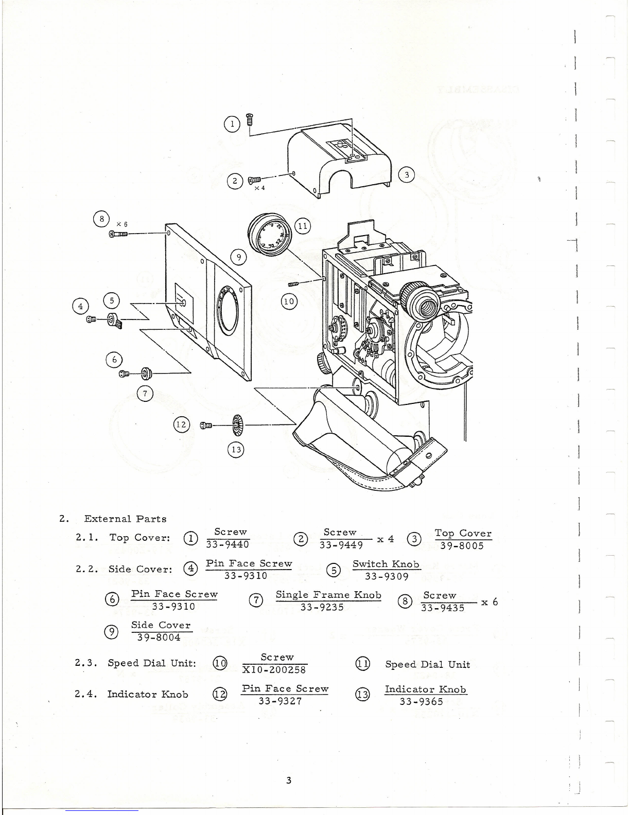
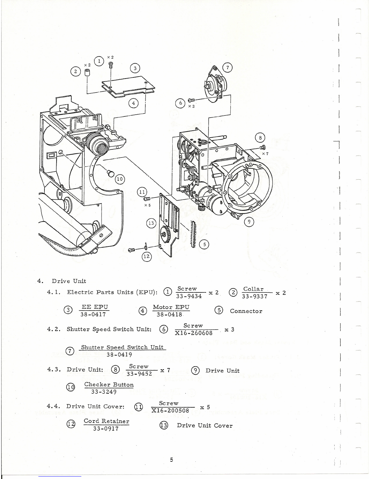
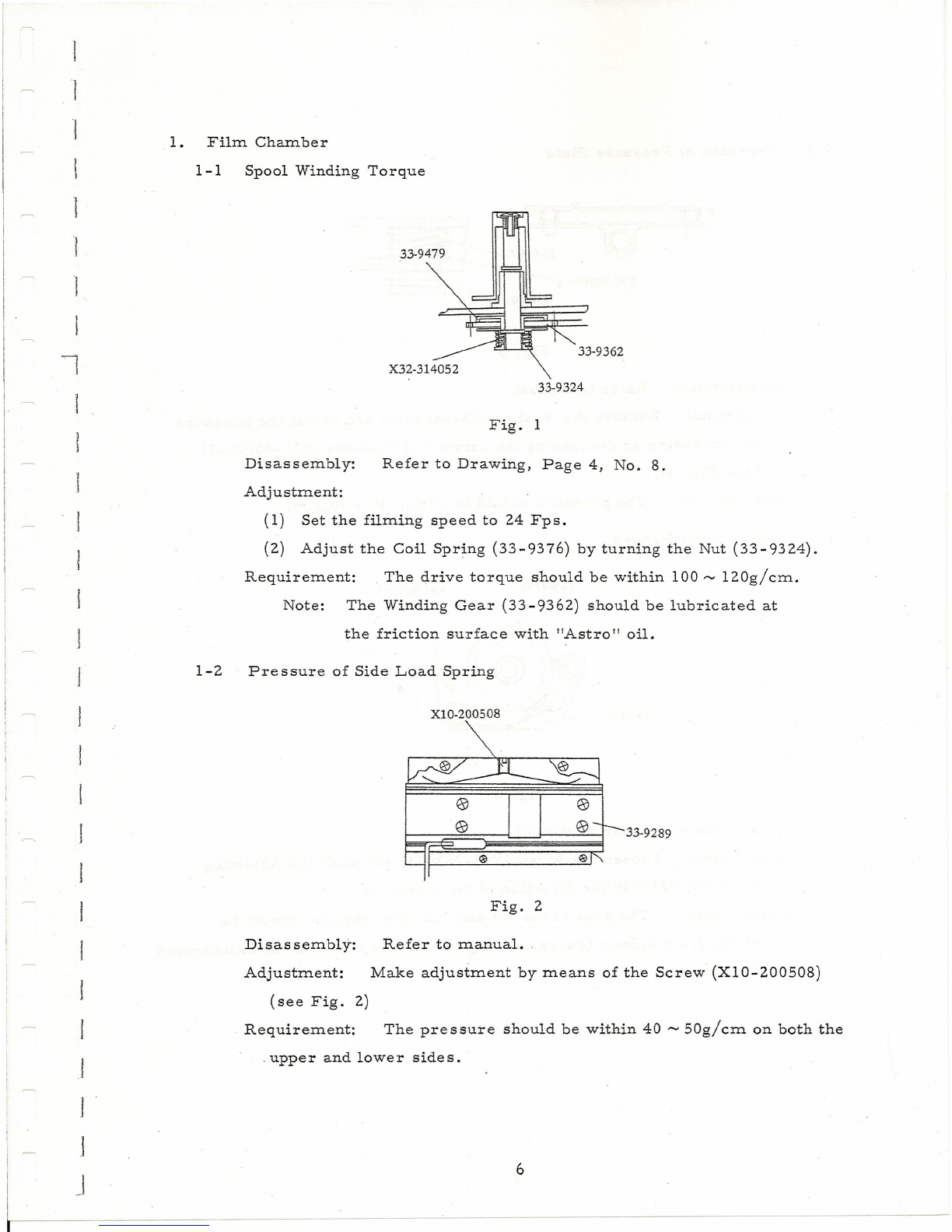
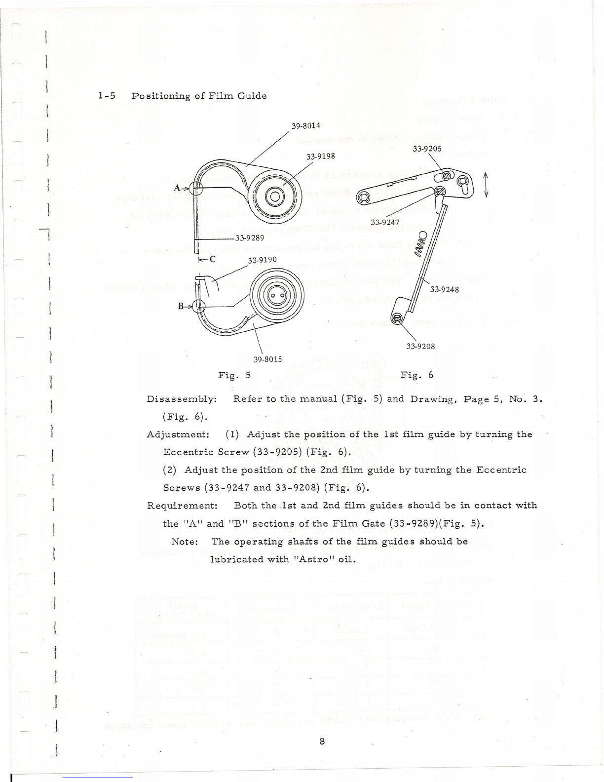
Canon SCOOPIC 16- M Assembly instructions
Other Canon Camcorder manuals

Canon
Canon XL 2 User manual

Canon
Canon MD120 User manual

Canon
Canon 310 XL User manual

Canon
Canon EOS C300 User manual

Canon
Canon Auto Zoom 318 M User manual

Canon
Canon UC8Hi User manual

Canon
Canon SCOOPIC 16M User manual

Canon
Canon VIXIA HF W11 Operating and maintenance manual

Canon
Canon VIXIA HF M300 User manual

Canon
Canon MVX150i User manual

Canon
Canon VIXIA HF M52 User manual

Canon
Canon EOS C100 Mark II User manual

Canon
Canon G2000 series User manual

Canon
Canon MVX10i User manual

Canon
Canon ZR500 User manual

Canon
Canon HG-10 User manual

Canon
Canon UC 9 Hi Color User manual

Canon
Canon MV5iMC User manual

Canon
Canon MV MVX30i User manual

Canon
Canon MVX100 User manual