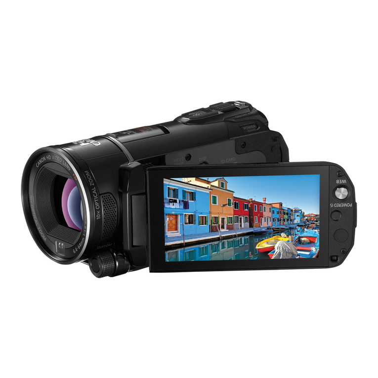
Canon Vixia HV40 User manual

PUB.DIM-0918-000
Canon
HD Camcorder II
Instruction Manual English
Camescope
HD
I . I
Manuel d'instruction
Fran~als
Videocamara HD I - I
Manual de Instrucciones
Espanol
VIXIA
HV40
MiniDt""""
Digital
Video
Cassette
I-IOV
HLJml
HDV1080i
t(
PictBridge
Please read also the following instruction manual
(electronic version
on
PDF file). For further details refer to
the installation guide.
Veuillez lire aussi
Ie
manuel d'instruction suivant (version
electronique sur fichier PDF). Pour d'autres details referez-
vous
au
guide d'installation.
Lea tambien
el
siguiente manual de instrucciones (version
electronica
en
archivo PDF). Para mayores detalles,
refierase a
la
guia de instalacion.
•
Digital
Video
Software
Cdnon

•.
....
-----------------_.
Important
Usage
Instructions
WARNING!
&
TO
REDUCE
THE
RISK
OF FIRE OR ELECTRIC SHOCK, DO
NOT
EXPOSE THIS
PRODUCT
TO RAIN
OR
MOISTURE.
WARNING!
it
TO REDUCE THE RISK OF ELECTRIC
SHOCK
AND TO REDUCE ANNOYING
INTERFERENCE, USE THE RECOMMENDED ACCESSORIES ONLY.
COPYRIGHT WARNING:
Unauthorized recording
of
copyrighted materials may infringe on the rights
of
copyright owners and be contrary to copyright laws.
HD
Camcorder, VIXIA HV40 Asystems
This device complies with Part 15 of the FCC Rules. Operation
is
subject to the following two conditions: (1) This
device may not cause harmful interference, and (2) this device must accept any interference received, including
interference that may cause undesired operation.
Note: This equipment has been tested and found to comply with the limits for class Bdigital device, pursuant to
Part
15
of the FCC Rules. These limits are designed
to
provide reasonable protection against harmful
interference
in
aresidential installation. This equipment generates, uses and can radiate radio frequency energy
and, if not installed and use
in
accordance with the instructions, may cause harmful interference to radio
communications. However, there
is
no guarantee that interference will not occur
in
aparticular installation. If this
equipment does cause harmful interference to radio or television reception, which can be determined
by
turning
the equipment off and on, the user
is
encouraged to try to correct the interference by one or more of the following
measures:
•Reorient or relocate the receiving antenna.
•Increase the separation between the equipment and receiver.
•Connect the equipment into an outlet
on
acircuit different from that to which the receiver
is
connected.
•Consult the dealer or an experienced radiolTV technician for help.
Use of shielded cable is required to comply with class Blimits
in
Subpart Bof Part
15
of FCC Rules.
Do not make any changes or modifications to the equipment unless otherwise specified
in
the manual.
If such changes or modifications should
be
made, you could
be
required to stop operation of the equipment.
Canon U.S.A., Inc.
One Canon Plaza, Lake Success, NY 11042, U.S.A.
Tel
No. (516)328-5600
CAUTION:
TO PREVENT ELECTRIC SHOCK, MATCH WIDE BLADE OF PLUG TO WIDE SLOT, FULLY
INSERT.
The Mains plug is used as the disconnect device. The Mains plug shall remain readily
operable to disconnect the plug in case
of
an accident.
CAUTION:
•Danger
of
explosion if the wrong type
of
batteries are attached. Use only the same type
of
batteries.
•Do not expose batteries
or
product to excessive heat such as the inside
of
acar under
direct sunlight, fire, etc.

---------------------------------------.
....
Important Warning
CAUTION
RiSK OF EL.ECTRIC SHOCK
DO
NOT OPEN
The lightning flash with arrowhead symbol, •
within an equilateral triangle, is intended to
alert the user to the presence
of
uninsulated
"dangerous voltage" within the product's
enclosure, that may be
of
sufficient magnitude
to constitute arisk
of
electric shock to persons.
CAUTION:
TO REDUCE THE RISK OF ELECTRIC
SHOCK, DO NOT REMOVE COVER (OR
BACK). NO USER-SERVICEABLE PARTS
INSIDE. REFER SERVICING TO
QUALIFIED SERVICE PERSONNEL.
The exclamation point, within an equilateral
triangle, is intended to alert the user to the
presence
of
importantoperating and
maintenance (servicing) instructions in the
literature accompanying the product. -
:::::J
-
"'"
o
Q.
c:;
(")
!:!:
o
:::::J

I
.....
-----------------------------------
IMPORTANT
SAFETY
INSTRUCTIONS
In
these safety instructions the word "product"
refers
to
the Canon
HD
Camcorder VIXIA HV40 A
and all its accessories.
1Read these instructions.
2Keep these instructions.
3Heed all warnings.
4Follow all instructions.
5Do not use this apparatus near water.
6Clean only with dry cloth.
7Do not install near any heat sources such
as radiators, heat registers, stoves, or
other apparatus (including amplifiers) that
produce heat.
8Do not defeat the safety purpose of the
polarized or grounding-type plug. A
polarized plug has two blades with one
wider than the other. Agrounding type plug
has two blades and athird grounding
prong. The wide blade or the third prong
are provided for your safety. Ifthe provided
plug does not fit into your outlet, consult an
electrician for replacement of the obsolete
outlet.
9Protect the power cord from being walked
on or pinched particularly at plugs,
convenience receptacles, and the point
where they exit from the apparatus.
10 Only use attachments/accessories
specified by the manufacturer.
11
Unplug this apparatus during lightning
storms
or
when unused for long periods
of
time.
12 Refer all servicing to qualified service
personnel. Servicing is required when the
apparatus has been damaged in any way,
such as power-supply cord or plug is
damaged, liquid has been spilled orobjects
have fallen into the apparatus, the
apparatus has been exposed to rain or
moisture, does not operate normally, or has
been dropped.
13 Read Instructions -All the safety and
operating instructions should be read
before the product is operated.
14 Retain Instructions -The safety and
operating instructions should
be
retained
for future reference.
15 Heed Warnings -All warnings
on
the
product and
in
the operating instructions
should be adhered to.
16 Follow Instructions -All operating and
maintenance instructions should be
followed..
17 Cleaning -Unplug this product from the
wall outlet before cleaning. Do not use
liquid or aerosol cleaners. The product
should be cleaned only as recommended
in
this manual.
18 Accessories -Do not use accessories not
recommended
in
this manual as they may
be hazardous.
19 Avoid magnetic or electric fields -Do not
use the camera close to
TV
transmitters,
portable communication devices or other
sources
of
electric or magnetic radiation.
They may cause picture interference,
or
permanently damage the camera.
20 Water and Moisture -Hazard of electric
shock -Do not use this product near
water
or
in
rainy/moist situations.
21
Placing or Moving -Do
not place on
an
unstable
cart, stand, tripod, bracket
or table. The product may
fall, causing serious injury
to achild or adult, and
serious damage to the
product.
Aproduct and cart combination should be
moved with care. Quick stops, excessive
force, and uneven surfaces may cause the
product and cart combination to overturn.
22 Power Sources -The CA-570 Compact
Power Adapter should be operated only
from the type
of
power source indicated on
the marking label. Ifyou are not sure of the
type
of
power supply to your home, consult
your product dealer
or
local power
company. Regarding other power sources
such as battery power, refer to instructions
in
this manual.
23 Polarization -The CA-570 Compact
Power Adapter
is
equipped with a
polarized 2-prong plug
(a
plug having one
blade wider than the other). The 2-prong
polarized plug will fit into the power outlet
only one way. This
is
asafety feature. If
you are unable to insert the plug fully into
the outlet, try reversing the plug. Ifthe plug
still fails to fit, contact your electrician to
replace your obsolete outlet. Do not defeat
the safety purpose
of
the polarized plug.
----------------------------------.....
•
26
Lightning -For added protection
of
this
product during alightning storm, or when it
is left unattended and unused for long
periods
of
time, disconnect it from the wall
outlet and disconnect the antenna. This will
prevent damage to the product due to
lightning and power-line surges.
27 Overloading -Do not overload wall outlets
and extension cords as this can result
in
a
risk
of
fire
or
electric shock.
28 Objects and Liquid Entry -Never push
objects
of
any kind into this product
through openings as they may touch
dangerous voltage points
or
short out parts
that could result
in
afire
or
electric shock.
Be careful not to spill liquid
of
any kind onto
the product.
24
Power Cord Protection -Power cords
should be routed so that they are not likely
to be walked on
or
pinched by items placed
upon or against them. Pay particular
attention to plugs and the point from which
the cords exit the product.
25 Outdoor Antenna Grounding -If an
outside antenna is connected to the
product, be sure the antenna is grounded
so as to provide some protection against
voltage surges and built-up static charges.
Section 810
of
the National Electrical
Code, ANSI /NFPA No.
70-1984,
provides information with respect to proper
grounding
of
the mast and supporting
structure, grounding
of
the lead-in wire to
an antenna discharge unit, size
of
grounding conductors, location
of
antenna
discharge unit, connection to grounding
electrodes, and requirements for the
grounding electrode. See figure
1.
~
-
..,
o
c.
s::::
n
=
o
~
-
•
29 Servicing -Do not attempt to service this
product yourself as opening or removing
covers may expose you to dangerous
voltage
or
other hazards. Refer all
servicing to qualified service personnel.
30 Damage Requiring Service -Disconnect
this product from the wall outlet and all
power sources including battery, and refer
servicing to qualified service personnel
under the following conditions:
a.
When the power-supply cord or plug is
damaged.
b.
If
any liquid has been spilled onto,
or
objects have fallen into, the product.
c.
Ifthe product has been exposed to rain
or water.
d.
If the product does not operate normally
even if you follow the operating
instructions.
Adjust only those controls that are
covered by the operation instructions.
Improper adjustment of other controls
may result
in
damage and will often
require extensive work by aqualified
technician to restore the product to its
normal operation.
e.
If the product has been dropped or the
cabinet has been damaged.
f.
When the product exhibits adistinct
change in performance. This indicates a
need for service.
31
Replacement Parts -When replacement
parts are required, be sure the service
technician has used replacement parts that
are specified by Canon or that have the
same characteristics as the original part.
Unauthorized substitutions may result
in
fire, electric shock or other hazards.
32 Safety Check -Upon completion
of
any
service or repairs to this product, ask the
service technician to perform safety checks
to determine that the product is
in
safe
operating order.
33 Heat -The product should be situated
away from heat sources such as radiators,
heat registers, stoves,
or
other products
(including amplifiers) that produce heat.
ANTENNA
LEAD
IN
WIRE
ANTENNA DISCHARGE
UNIT (NEC SECTION 810-20)
GROUNDING
CONDUCTORS
(NEC SECTION 810-21)
GROUND CLAMPS
POWER SERVICE GROUNDING
ELECTRODE SYSTEM
(NEC ART 250. PART H)
EXAMPLE OF ANTENNA GROUNDING AS
PER NATIONAL ELECTRICAL CODE
.--
NEC -NATIONAL
ELECTRICAL CODE
ELECTRIC
SERVICE
EQUIPMENT
Fig. 1
When replacement ofthe power supply is required, please return it to the responsible nearest
Canon Service Center and please replace it with the same type number CA-570.
II
.....
----------------------------------
The Adapter can be used with apower supply between 100 and 240 VAC. For areas where
120 V
At
power
is
not used, you will need aspecial plug adapter. Contact your nearest Canon
Service Center for further information.
IThis Class Bdigitalapparatus complies with Canadian ICES-003.

-----------------_
.....
Ill.>
Enjoying
High-Definition
Video
•Preserve your most treasured memories, be it unforgettable scenery
or
cherished moments spent with family and friends, with high-definition video
recordings
of
aquality second only to actually being there. •
What
is
High-Definition
Video?
High-definition video (HDV) allows you to record
video
of
unparalleled high quality on regular
miniDV tapes.
HDV
is composed
of
1,080
horizontal lines
-that
is more than twice the
number
of
horizontal lines and approximately 4
times the number
of
pixels
in
standard-definition
TV
broadcasts-
resulting
in
eye-catching colors
and richly detailed video recordings. 1,080 lines
-
~
-
....
o
Q.
s:::
(")
~
o
~
How
to
play
back
your
HDV
recordings?
•On ahigh-definition TV (HDTV)
(lIJ
72)
HDV recordings will be played back
in
their original high quality.
•On standard definition TVs
(lIJ
73)
HDV
recordings will be down-converted to match the resolution
of
the
TV
set.
What
is
the
Cinema
Mode?
Give your recordings acinematic look by using the
[0
CINE MODE]
recording program (OJ 48). Combine this recording mode with the high-
definition, 24 fps progressive frame rate [lIHDv1l24 HDV(PF24)] or
[EJHDVU24F
HDV(24F))
(lIJ
40) to get the enhanced effect
of
the 24p Cinema
Mode.

•
.•...
------------------------------
Table
of
contents
Introduction
Enjoying High-Definition Video 7
About this Manual
11
Getting to Know the Camcorder
Supplied Accessories 13
Components Guide 14
Screen Displays 17
Preparations
Getting Started
Charging the Battery Pack 20
Inserting and Removing aTape 22
Inserting and Removing aMemory Card 22
Preparing the Camcorder 23
The Wireless Controller 23
Adjusting the LCD Screen 24
Using the Menus
Selecting
an
Option from the FUNC. Menu 25
Selecting an Option from the Setup Menus 25
First Time Settings
Changing the Language 26
Changing the Time Zone 26
Setting the Date and Time 27
Basic Functions
Recording
Recording Movies 28
Recording Still Images 29
Zooming 30
Playback
Playing Back Movies
31
Adjusting the Volume: Speaker and Headphones 32
Returning to aPre-marked Position
33
Locating the End
of
the Last Scene 34
Locating Scenes by Recording Date 34
Viewing Still Images 35
Magnifying the Playback Image 36
Advanced Functions
Menu Options Lists
FUNC. Menu Options
37
Setup Menus 39
Using the Recording Programs
Recording Programs 48
Giving aCinematic Look to your Recordings 49
PFlexible Recording: Changing the Aperture and Shutter Speed 49
Special Scene: Recording Programs to Match Special Conditions
51

•
----------------------------
....
I
Adjusting the Picture: Exposure, Focus and Color
Manual Exposure Adjustment and Automatic Backlight Correction 52
Manual Focus Adjustment 53
Magnifying the Image on the Screen 53
White Balance 54
Image Effects 55
Still Image Recording Options
Selecting the Size and Quality
of
Still Images 56
Capturing aStill Image while Recording Movies
57
Light Metering Mode 58
Automatic Focus Priority 59
Continuous Shooting and Exposure Bracketing 60
Other Functions
Using the CUSTOM Key
61
On-Screen Displays
61
Flash 63
Mini Video Light 64
Self Timer 64
Audio Recording Level 65
Digital Effects 67
Editing Functions
Still Image Options
Erasing Still Images 69
Protecting Still Images 69
Initializing the Memory Card 70
External Connections
Connecting to a
TV
or VCR
Connection Diagrams
71
Playback on a
TV
Screen 74
Recording to aVCR or Digital Video Recorder 75
Analog Line-In Recording
~
76
Digital Video Dubbing 77
Analog/Digital Conversion 78
Connecting to aComputer
PC Connection Diagrams 80
Transferring Video Recordings
81
Transferring Still Images -Direct Transfer 82
Transfer Orders 83
Connecting to aPrinter
Printing Still Images -Direct Print 84
Selecting the Print Settings 85
Trimming Settings 87
Print Orders 87
Additional Information
Trouble?
TrOUbleshooting 89
List
of
Messages 93
-
~
-
a
Q.
t:
(")
~
o
~

I
.....
------------------------------
Do's and Don'ts
Handling Precautions
96
Maintenance/Others
99
Cleaning the Video
Heads
99
Using
the
Camcorder
Abroad
100
General Information
System
Diagram 101
Optional Accessories 102
Product
Codes
105
Specifications 106
Index
109
Trademark
Acknowledgements
•
miniSDTM
is atrademark
of
SO
Card Association.
•Microsoft, Windows and Windows Vista are trademarks or registered trademarks
of
Microsoft Corporation
in
the United States and/or other countries.
•Macintosh and Mac
as
are trademarks of Apple Inc., registered
in
the U.S. and other
countries.
•
MiniW
is atrademark.
•HOV and the HOV logo are trademarks
of
Sony Corporation and Victor Company
of
Japan,
Ltd. (JVC).
•HOMI, the HDMI logo and High-Definition Multimedia Interface are trademarks or
registered trademarks
of
HOMI Licensing LLC.
•Other names and products not mentioned above may be trademarks or registered
trademarks of their respective companies.
•ANY USE OF THIS PRODUCT OTHER THAN CONSUMER PERSONAL USE
IN
ANY MANNER
THAT COMPLIES WITH THE MPEG-2 STANDARD FOR ENCODING VIDEO INFORMATION
FOR PACKAGED MEDIA IS EXPRESSLY PROHIBITED WITHOUT ALICENSE UNDER
APPLICABLE PATENTS
IN
THE MPEG-2 PATENT PORTFOLIO, WHICH LICENSE IS
AVAILABLE FROM MPEG LA, L.L.C., 250 STEELE STREET, SUITE 300, DENVER,
COLORADO 80206.

-------
...
·1
About
this
Manual
Thank you for purchasing the Canon VIXIA HV40. Please read this manual carefully
before you use the camcorder and retain it for future reference. Should your camcorder
fail to operate correctly, refer to the Troubleshooting table
(CD
89).
Conventions
Used
in
the
Manual
...
IMPORTANT: Precautions related to the camcorder operation.
•
CD
NOTES: Additional topics that complement the basic operating procedures.
•e POINTS TO CHECK: Restrictions that apply
if
the function described
is
not
available
in
all operating modes (the operating mode to which the camcorder should be
set, etc.).
•
OJ
:Reference page number.
•"Screen" refers to the LCD and the viewfinder screen.
•The photos included in the manual are simulated pictures taken with astill camera.
Setting
the
Dat,
and Time
[!lDATEiTlME SETUP
~
J\
•
'.
Buttons and switches to be operated
-----------~....:.~=~=-~;
(~~
.~.)
•II you
do
not use ttle camcorder for about 3
months, the built-In rechargeable lithium battery
may discharge completely and the dale and
lime selling may
be
lost In such case, recharge
lhe bUill-In lithium battery
(W
98) and set the
lIme zone date and lime again
•
Yoo
can also change
file
date
format
{W
47}
1
Press~
2
Select
(£~)
the
r~
Icon
and
press
Brackets
[]
and capital letters are used to refer to menu
18l.oopen.
_
___
I
__
I--'~~~~·,~~·
.';;'
""t<j\~tlOAr::TEIT:::::'ME~S~ET~UP]
I
options as they are displayed on screen. Menu options
in
Iand
press
(
'"
.
boldface indicate the default setting (for example [ON], 4
~;~tI""
[OATEfTIME]
ndpress
[0
FF]) The first field of the date will be
•indicated with blinking up/down
arrows
5
Change
(4~)
each
field
of
the
date
and
time
and
move
(.,.)
to
the
next
field.
6
"'res~~
start
the
clock.
Names ofbuttons and switches otherthan the joystick are 7--7:......:P=
...
~ocloseth.m.nu.
indicated within a"button" frame (for example I
FUNC.
p.

I
....
------~~~~~-
About
the
Joystick
and
the
Joystick
Guide
The
mini
joystick
allows you to control
many
of
the
camcorder's
operations
and
to
make
selections and changes in the
camcorder's
menus.
Push the joystick
up,
down, left or right
(i;.T,
....
~
)
to
select
an
item or change --+-[!<l'1lS
settings. Press the joystick itself (8 )to save the
settings or confirm
an
action. On menu
screens, this is indicated by the SET icon
mi·
The functions assigned to the joystick change according to the operation mode and the
camcorder's settings. Press
(8)
to display/hide the joystick guide to remind you of the
joystick's functions.
EXP
- +
NEXT
¥
When the guide contains multiple 'pages', [NEXT] and the page number
....-----
icon
(¥
)will appear at the bottom position. Push the joystick
(T)
toward [NEXT] to display the next
'page'
of
the guide.
About
the
Operating
Modes
The camcorder's operating mode is determined by the positions
of
the
~
switch and the
Icrol
/~
switch.
In
the manual,
~.~l
indicates that afunction is available
in
the operating
mode shown and indicates that the function
is
not available. When no operating mode
icons are given, the function is available
in
all operating modes.
Operating
Mode
~
Switch
Icrol/~
Switch
Icon
Display
Operation
CD
~
Recording movies
~
Q§
on
the tape
28
(Tape)
c:g
Recording still images
~
~
on the memory card
29
(Memory card)
~
Playing movies
~
~
from the tape
31
(Tape)
c:g
Viewing still images
~
[B]
from the memory card 35
(Memory card)
PLAY
(CA~RAI
CAMERA

~~--~~~~---~~-~~---_
••••
Getting
to
Know
the
Camcorder
I
,--S_U_p_p_lie_d_.A_·C_c_e-rs_so_r_ie_s_.
-----,----------,-----------,.
CA-570 Compact Power BP-2L13 Battery Pack WL-D87 Wireless
Adapter Controller
(inc!. power cord)
Lithium Button Battery
CR2025 for Wireless
Controller
:::s
-
"'"
o
Co
c:
(")
-
o
:::s
-
DIGITAL VIDEO
SOLUTION DISK
Software CD-ROM* and
Installation Guide
CTC-1qO/S Component STV-250N Stereo Video IFC-300PCU
Cable Cable USB Cable
Red,
Green'
Blue plugs Yellow' Red,
White
plugs
*Includes the electronic version
of
the Digital Video Software instruction manual
on
PDF file.
Online product registration for USA Customers only.
Register your product online at www.registercanon.com
./
Protect your product
We will keep the model number and date
of
purchase
of
your new Canon product on
file to help you refer to this information in the event
of
an insurance claim such as loss
or theft.
./
Receive information on new products and promotions
Upon your request, we will send you information on Canon new products and
promotions.
The serial number
of
this product can be found at the battery attachment unit
of
the
camcorder. Write down the number and other information here and retain this book as a
permanent record
of
your purchase to aid identification in case
of
theft.
Date
of
Purchase: Model Name: VIXIA HV40 A
Purchased From: Serial No.:
Dealer Address:
Dealer Phone No.:

I
Getting
to
Know
the
Camcorder
•••••
------------------
Components
GUide
Left
side
view
®®®
I
Ii
nn·:
nt..
PUSH
LJf
EJECT
Right
side
view
®
QJ)
Front
view
@@
CD
FOCUS lever (OJ 53)
CV
CUSTOM key (OJ 61)
WFOCUS button (OJ 53)
@Speaker
®DISP. (display) button (OJ 61)/
LCD backlight button (long press) (OJ 24)
®LIGHT button (OJ 64)/
I!dJ
ttV
(print/share) button (OJ 82, 85)
(J)
USB terminal (OJ 80)
®CARD access indicator (OJ 29)/
CHARGE indicator (OJ 20)
®Memory card slot (OJ 22)
@
Icrol/c:g
(tape/card) switch (OJ 12)
@Mode switch (OJ 48)
@Terminal cover
@MIC (microphone) terminal (OJ 66)
(3)
AV
terminal (OJ 71)/
o(headphones) terminal (OJ 32)
@COMPONENT OUT terminal (OJ 71)
@Grip belt (OJ 23)
@Instant AF sensor (OJ 39)
@Flash
(OJ 63)
@Mini video light (OJ 64)
@Remote sensor (OJ 23)
Names
of
buttons and switches other than the
joystick are indicated within a"button" frame (for
example IFUNC·I)·

-----------------
....
Getting
to
Know
the
Camcorder
II
Bottom
view
(J)
Power indicator
®Terminal cover
;j
-
a
c.
s::
(")
::::!:
o
;j
-
@Lock button
@Zoom lever (OJ 30)
©DC IN terminal
(OJ
20)
@Advanced accessory shoe
(OJ
63,66)
@J
Stereo microphone
@Cassette compartment (OJ 22)
@Tripod socket
(OJ
29)
@OPEN/EJECT
~
switch
(OJ
22)
@HDMI
OUT
terminal
(OJ
71,74)
@Cassette compartment cover
(OJ
22)
@PHOTO button
(OJ
29)
@
~
(fast forward) button
(OJ
31)/
Zoom
in T(telephoto) button
(OJ
30)
@FUNC.
button (OJ
25,37)
@
~
/11
(play/pause) button
(OJ
31)/
START/STOP button
(OJ
28)
(j])Serial
number
-The serial
number
label is
located on the back surface
of
the battery
attachment unit. Remove the battery pack to
find it.
®
lilll\qij;J
switch
(OJ
12)
@ • (stop) button
(OJ
31)/
MAGNIFY button
(OJ
53)
@
HDVIDV
terminal
(OJ
71, 80)
@
....
(rewind) button (OJ 31)/
Zoom
out
W(wide-angle) button
(OJ
30)
®
RESET
button
(OJ
89)
®START/STOP button
(OJ
28)
®Joystick (OJ 12)
®Viewfinder
(OJ
23)
...:::CD:::....::L--=-C.=.D-:s:....::c_re_e_n~(-=OJ=-2_4..:....)
•
~
Dioptric adjustment lever
(OJ
23)
Top
view
Back
view
CD
@@
!
@BATTERY RELEASE switch (OJ 20)
@Strap mount
Names
of
buttons
and
switches other than the
joystick are indicated within a"button" frame (for
example [FUNC.I).

I
Getting
to
Know
the
Camcorder
•••••
-----------------
Wireless
Controller
WL·D87
CD
START/STOP button (OJ 28)
@+/11
~
button (OJ 31)
®ZERO SET MEMORY button (OJ 33)
@TV SCREEN button (OJ 45)
®X2 button (OJ 31)
Q1)
STOP •button (OJ 31)
®
-/
.....
II
button (OJ 31)
@PLAY
~
button (OJ 31)
®PAUSE
II
button (OJ 31)
(jJ)
Zoom buttons (OJ 30)
@
FF
~
button (OJ 31)
WCARD
-/+
buttons (OJ 35)
®
DISP.
(on-screen display) button (OJ 61)
@PHOTO button (OJ 29)
WDATE SEARCH
~/~
buttons (OJ 34)
®REW
....
button (OJ 31)
(])
SLOW
••
button (OJ 31)
.~---,.,.,
..
_--_._-®
(J)
@._--_.,
....
_,/
@ .
,J
ell
----
@
----,----b
@---+
.®--~

--------------------.
....
Getting
to
Know
the
Camcorder
I
Screen
Displays
(:CAMluiml
Recording
Movies
(j)
®®
@
CD
@
(3)
G)
@-
®;
@
®Magnification
(CD
46,53)
(J)
Self timer
(CD
64)
®Recording reminder
®Instant AF
(CD
39)/Manual focus
(CD
53)
®Recording standard (HDV
or
DV)
(CD
40)
Q])
DV recording mode
(CD
41)
@Tape operation
@Time code (hours :minutes :seconds)
(j3)
Remaining tape
®Remaining battery charge
@DV audio mode
(CD
41)
@Microphone attenuator
(CD
65)
@Wind screen off
(CD
41)
@Image stabilizer
(CD
40)
@Headphones output
(CD
32)
@Backlight correction
(CD
52)
•
•
~
-
.,
o
Q.
c::::
n
-
o
~
(CAMERA'c:gj
Recording
Still
Images
@--
I~--
CD
Recording program
(CD
48)
(~White
balance
(CD
54)
®Image effect
(CD
55)
@)
Digital effects
(CD
67)
®Still image quality/size
(simultaneous recording)
(CD
57)
................
@j
--@>
@Function assigned to the CUSTOM key
(CD
61)
@Focus assist functions
(CD
45)
@Level marker
(CD
45)
@Condensation warning
(CD
99)
@Mini video light
(CD
64)
@Remote sensor off
(CD
46)
@Audio level indicator (microphone)
(CD
65)
@Zoom
(CD
30), Exposure
0-1-0
(CD
52)
®Light metering mode
(CD
58)
®Drive mode
(CD
60)
@$till image quality/size
(CD
56)
@Number of still images available
on
the
memory card
®AF frame
(CD
59)
@Camcorder shake warning
(CD
39)
@Advanced accessory shoe
.,$"
(CD
101)
@Flash
(CD
63)
@Autofocus (AF) and exposure (AE) locked
(CD
29)

I
Getting
to
Know
the
Camcorder
....
...--------------------

-------------------
••••
Getting
to
Know
the
Camcorder •
®Data code (OJ 62)
@Time code (hours: minutes: seconds: frames)
Q) Remaining tape
~
-
...,
o
Q.
t:
(")
~
o
~
-
®Search function display
END SEARCH (OJ 34)/
DATE SEARCH (OJ 34)
0)
Quality/size for capturing still images (OJ 58)
®Audio level indicator (OJ 65)
®
Recording
made
in
[U
....
ovS24F
HDV(24F)]
mode
(OJ
40)
CD
Tape operation •
--=----------------
®
I
eJ)
@
.....
PI.AY·C]I
Viewing
Still
Images
PLAY,eJl
Playing
Movies
363-6307
l@jj
14/14
~j
CD
Image number (OJ 42)
@Current image /Total number
of
images
Q) Histogram (OJ 62)
P204Sx1536
MF
SV
0.16MB
[$J
;;!:~
~
F
2.
8
!!!l±0.00
1/30
~
L
OCT,
25, 2009 9:
20
AM
®Image protection mark (OJ 69)
®Still image quality/size
®Date and time of recording
(J)
Recording program (OJ 48)
®Manual focus (OJ 53)
®Light metering mode (OJ 58)
@Manual exposure (OJ 52)
Q1J
Flash (OJ 63)
®White balance (OJ 54)
®Shutter speed (OJ 49)
QJ
Aperture value (OJ 49)
@Image size (OJ 56)
@File size
QD
Image effect (OJ 55)
...............
(j)
..
@
, @
,.
..
,
..
,
..
,
..
""
..
,
..
",.".,
..
,
..
"""""
..
@
.............................
@
H
P
2048x1536
MF
<9v
O.
16
MB
[s]
~:!};
F
2.
8
IE
~±O.
00
1130

Getti.ng
Started
Charging
the
Battery
Pack
The camcorder can be powered with a
battery pack or directly using the compact
power adapter. Charge the battery pack
before use.
1Connect the power cord to the
compact power adapter.
2Plug the power cord into apower
outlet.
3Connect the compact poweradapter
to the camcorder's
DC
IN
terminal.
Remove the battery
terminal cover
before attaching
the
battery pack
4Attach the battery pack to the
camcorder.
Press the battery pack softly into the
battery attachment unit and slide it up
until it clicks
in
place.
SCharging will start when the
camcorder is turned off.
•The CHARGE indicator starts
flashing. The indicator will go out when
the battery pack
is
fully charged.
•
You
can also use the compact power
adapter without attaching abattery
pack.
•When the compact power adapter is
connected, even if abattery is
attached its power will not be
consumed.
ONCE
THE
BAnERY
PACK
IS
FULLY
CHARGED
1Disconnect the compact power
adapter from the camcorder.
2Unplug the power cord from the
power outlet and the compact
power adapter.
To
REMOVE
THE
BAnERY
PACK
Slide [BATTERY RELEASE]
in
the
direction of the arrow and hold it
pressed down. Slide the battery pack
down and then pull it out.
•You may
hear
some noise from the compact
power adapter during use. This is not a
malfunction.
•
We
recommend charging the battery pack in
temperatures between
10°C
and 30 °C (50
OF
and 86
OF).
Outside the temperature range
of
o°C to
40°C
(32
OF
to 104
OF),
the charging will
not start.
•Do not connect to the camcorder's DC
IN
terminal
or
to the compact power adapter any
electrical equipment that is not expressly
recommended for use with this camcorder.
•
To
prevent equipment breakdowns and
excessive heating, do not connect the supplied
Other manuals for Vixia HV40
3
Table of contents
Other Canon Camcorder manuals

Canon
Canon DVD CAMCORDER DC410 User manual

Canon
Canon E 500 User manual

Canon
Canon 2487B001 User manual

Canon
Canon HG-10 User manual

Canon
Canon HV30E User manual

Canon
Canon DM-GL1 User manual

Canon
Canon UC 8 Hi User manual

Canon
Canon FS10 User manual

Canon
Canon Optura 30 - optura 30 minidv camcorder User manual

Canon
Canon LEGRIA HF200 User manual

Canon
Canon mv880xi User manual

Canon
Canon mvx1sI User manual

Canon
Canon DC100 - WL Remote Control User manual

Canon
Canon Vixia hf r72 User manual

Canon
Canon ELURA 50 User manual

Canon
Canon LEGRIA HF M32 User manual

Canon
Canon XA60 User manual

Canon
Canon XA20 User manual

Canon
Canon LEGRIA HF R506 User manual

Canon
Canon Vixia mini X User manual