Canon dp-v3010 User manual

Instruction Manual
Video Display
•Beforeuse,besuretoreadthisguide,includingthe
safetyandhandlingprecautions.
•Readingthisguidewillhelpyoulearntousethevideo
displayproperly.
•Storethisguidesafelysothatyoucanuseitinthefuture. English

2Table of Contents
Table of Contents
Introduction .................................................................................................................................. 4
About this manual .................................................................................................................................... 4
Trademarks .............................................................................................................................................. 4
Safety Precautions ....................................................................................................................... 5
Handling Precautions ................................................................................................................... 6
Features........................................................................................................................................ 8
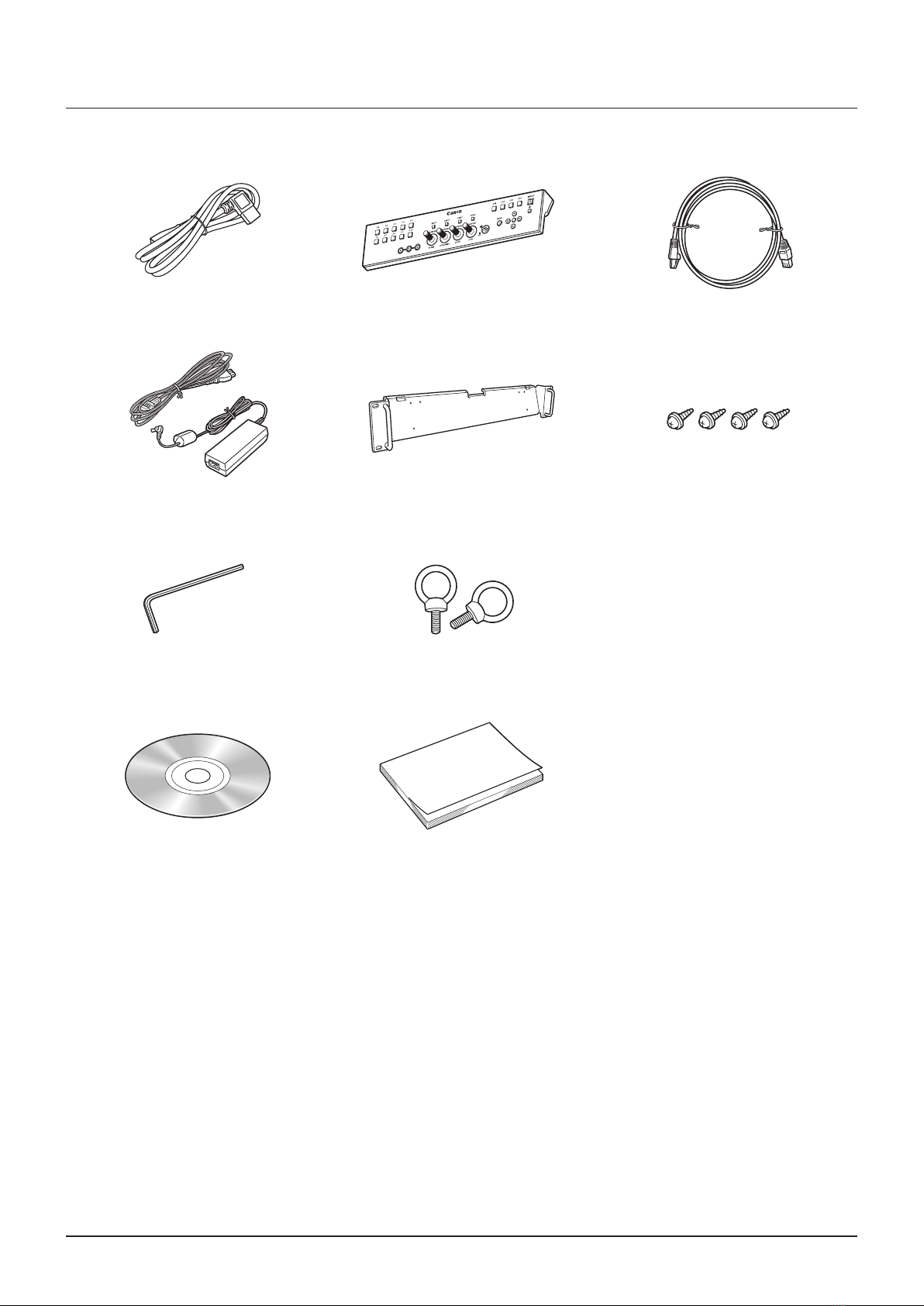
Supplied Accessories................................................................................................................. 10
Nomenclature ............................................................................................................................. 11
Main Unit................................................................................................................................................ 11
Display Controller ................................................................................................................................... 13
Installation/Connection .............................................................................................................. 15
How to Carry the Main Unit .................................................................................................................... 15
Preventing from Tipping ......................................................................................................................... 15
Connecting the Main Unit to Input Devices ............................................................................................. 16
Connecting the Main Unit to the Display Controller ................................................................................. 19
Installing the Display Controller on the Rack ........................................................................................... 20
Mounting the Main Unit on a Stand or Wall............................................................................................. 21
Turning on the Power ................................................................................................................. 22
Turning on the Power of the Main Unit.................................................................................................... 22
Turning on Main Unit Power from the Display Controller.......................................................................... 22
Pairing ........................................................................................................................................ 23
Pairing the Main Unit with the Display Controller ..................................................................................... 23
Re-pairing .............................................................................................................................................. 24
Operating the Display Controller ................................................................................................ 25
Adjusting the Image Quality .................................................................................................................... 25
Adjusting the Image Quality on CDL ....................................................................................................... 25
Temporarily Saving Parameters (Anchor Point Setting)............................................................................ 26
Using the Function (F) Buttons ............................................................................................................... 26
Using the Channel (CH) Button............................................................................................................... 27
Checking Signal Information and Status of the Main Unit........................................................................ 27
Using the OSD Menu.................................................................................................................. 28
Basic Operation ..................................................................................................................................... 28
Adjusting Image Quality While Viewing the Entire Image ......................................................................... 29
Calibration without a PC......................................................................................................................... 31
Export/Import......................................................................................................................................... 32
Set Date/Time ........................................................................................................................................ 34
Inputting Characters............................................................................................................................... 34

3Table of Contents
OSD Menu.................................................................................................................................. 35
OSD Menu Index.................................................................................................................................... 35
Adjustment............................................................................................................................................. 40
Channel Settings.................................................................................................................................... 49
Display Settings...................................................................................................................................... 51
Marker Settings...................................................................................................................................... 54
Function Settings ................................................................................................................................... 59
System Settings ..................................................................................................................................... 64
Signal Information................................................................................................................................... 68
System Information ................................................................................................................................ 68
Main specifications/Performance............................................................................................... 69
Main Unit................................................................................................................................................ 69
Display Controller ................................................................................................................................... 70
Dimensions ............................................................................................................................................ 71
Appendix .................................................................................................................................... 72
Supported Signal Format ....................................................................................................................... 72
Image/Frame Display.............................................................................................................................. 87
Error Messages .......................................................................................................................... 89
Troubleshooting.......................................................................................................................... 91
Software Used in This Product................................................................................................... 93
Index........................................................................................................................................... 95

4Introduction
Introduction
ThankyouforpurchasingtheVideoDisplayDP-V3010.
TheOnScreenDisplay(thereafterreferredtoOSD)defaultlanguagesettingisEnglish.TochangetheOSDmenu
languagesetting,pleaserefertop.64.
About this manual
Someoftheillustrationusedinthemanualhavebeensimpliedforclarity.
Conventions used in this manual
:Indicatesareferencepage.
Note:Indicatesanote.
Reference:Indicatesreferenceinformation.
CAUTION:Indicatesanitemyoumustobserve.
Trademarks
• DisplayPortandVESAareregisteredtrademarksortrademarksofVideoElectronicsStandardsAssociationinthe
U.Sandothercountries.
• Otherproductandcompanynameshereinaretrademarksorregisteredtrademarksoftheirrespectiveowners.

5Safety Precautions
Safety Precautions
For the customers in the U.S.A.
ThisequipmenthasbeentestedandfoundtocomplywiththelimitsforaClassAdigitaldevice,pursuanttoPart15of
theFCCRules.
Theselimitsaredesignedtoprovidereasonableprotectionagainstharmfulinterferencewhentheequipmentis
operatedinacommercialenvironment.Thisequipmentgenerates,uses,andcanradiateradiofrequencyenergy
and,ifnotinstalledandusedinaccordancewiththeinstructionmanual,maycauseharmfulinterferencetoradio
communications.Operationofthisequipmentinaresidentialareaislikelytocauseharmfulinterferenceinwhichcase
theuserwillberequiredtocorrecttheinterferenceathisownexpense.
Donotmakeanychangesormodicationstotheequipmentunlessotherwisespeciedinthemanual.Ifsuchchanges
ormodicationsshouldbemade,youcouldberequiredtostopoperationoftheequipment.
UseofshieldedcableisrequiredtocomplywithclassAlimitsinSubpartBofPart15ofFCCRules.
ThisdevicecomplieswithPart15oftheFCCRules.Operationissubjecttothefollowingtwoconditions:(1)Thisdevice
maynotcauseharmfulinterference,and(2)thisdevicemustacceptanyinterferencereceived,includinginterference
thatmaycauseundesiredoperation.
CanonU.S.AInc.
OneCanonPark,Melville,NY11747,U.S.A.
TelNo.(631)330-5000
For the customers in Canada
CANICES-3(A)/NMB-3(A)
For the customers in Europe
Warning:
ThisisaclassAproduct.Inadomesticenvironmentthisproductmaycauseradiointerferenceinwhichcasetheuser
mayberequiredtotakeadequatemeasures.
CANONINC.
30-2,Shimomaruko3-chome,Ohta-ku,Tokyo146-8501,Japan
CANONEUROPAN.V.
Bovenkerkerweg59,1185XBAmstelveen,TheNetherlands
OnlyforEuropeanUnionandEEA(Norway,IcelandandLiechtenstein)
Thissymbolindicatesthatthisproductisnottobedisposedofwithyourhouseholdwaste,
accordingtotheWEEEDirective(2012/19/EU)andnationallegislation.Thisproductshould
behandedovertoadesignatedcollectionpoint,e.g.,onanauthorizedone-for-onebasis
whenyoubuyanewsimilarproductortoanauthorizedcollectionsiteforrecyclingwaste
electricalandelectronicequipment(EEE).Improperhandlingofthistypeofwastecouldhave
apossiblenegativeimpactontheenvironmentandhumanhealthduetopotentiallyhazardous
substancesthataregenerallyassociatedwithEEE.Atthesametime,yourcooperationinthe
correctdisposalofthisproductwillcontributetotheeffectiveusageofnaturalresources.For
moreinformationaboutwhereyoucandropoffyourwasteequipmentforrecycling,please
contactyourlocalcityofce,wasteauthority,approvedWEEEschemeoryourhouseholdwaste
disposalservice.FormoreinformationregardingreturnandrecyclingofWEEEproducts,please
visitwww.canon-europe.com/weee.

6Handling Precautions
Handling Precautions
Places to avoid using the video display
Donotusethevideodisplayinthefollowingplacesorconditions.
• Placeswithexcessivedustorhumidity
• Places
thatwillexposethevideodisplaytodirectsunlight,smoke(suchasfromakeroseneheaterorothersuchsource)
orsteam
• Nearheatsources,humidiersorammablegas
• Nearawindowduringrainorsnow
• Nearwaterorotherplacesthatcouldcausemoisturetoformonthevideodisplay
Screen Handling
• Thescreenmaybedamagedifitisexposeddirectlytostronglightsource.Pleasetakeprecautionswhenplacingit
nearawindow.
• Donotpressrmlyonthescreen,scratchitorplaceanobjectonthescreen.Itcancausenon-uniformityordamage
tothepanel.
• Thescreenandcabinetmaybecomewarmduringuse.Notethisdoesnotconstituteamalfunction.
About Backlight
Thebacklighthasalimitedservicelifesoitsbrightnessmaydegradeandcolormaychangeduetoaging.
About Temporary Screen burn-in
Ifastationaryimageisdisplayedforaprolongedperiod,screenburn-inmayoccurwhereyouseeremnantsofwhat
wasdisplayed.ThisisacharacteristicofLCDandisnotafailure.However,thisisonlytemporaryandwilldisappear
whenplayingvideo.
About the LCD screen
Thescreenisproducedusingextremelyhigh-precisionmanufacturingtechniques,withmorethan99.99%ofthepixels
operatingtospecication.Lessthan0.01%ofthepixelsmayoccasionallymisreorappearasblack,red,blueor
greendots.Inaddition,thistendencymayincreasethroughlongtermuseduetocharacteristicoftheLCDpanel.
Thesedonotconstituteamalfunction.
Condensation
Ifthisequipmentisbroughtintoawarmroomwhileitiscoldoriftheroomisheatedsuddenly,condensationmayform
onthesurfaceorinsidetheequipment.Notethattheequipmentmaybedamagedifitisusedundersuchcondition.
Ifcondensationhasformedonthesurfaceorinsidetheequipment,donotusethevideodisplayasitmayget
damaged.Turnthepoweroffandwaituntilthecondensationhasevaporatedbeforeusingthevideodisplay.

7Handling Precautions
Cleaning
• Beforecleaning,pleaseunplugthepowerplugfromthewalloutlet.
• Thescreenhasaspecialsurfacetreatment,avoidtouchingitdirectlywithyourhand.Inaddition,neverafx
adhesiveobjectssuchasseals.
• Neverusealcoholorbenzene,thinner,acidiccleaningsolution,alkalinecleaningsolution,abrasiveorchemical
wipesbecausethesewilldamagethescreen.
• Ifthescreenisdirty,wipegentlywithsoftdryclothsuchascleaningclothoreyeglassescleaningcloth.Wipingthe
screentoohardmaycauseunevennessonthescreenordamagetheLCDpanel.Thescreenmaybescratchedif
wipedtoohardwithacleaningclothwithforeignparticlesattached.
• Whenthescreenisextremelydirty,wipewithsoftclothsuchascleaningclothoreyeglassescleaningcloth
moistenedwithwater-dilutedneutraldetergent.
• Useablowertoremovedustfromthesurfaceofthescreen.
• Sincethecabinetaroundthescreenhasaspecialsurfacetreatment,wipingofftheareamayfadeitssurfacecolor.
• Wipedirtoncabinetwithasoftcloth.Ifthescreenisverydirty,useamoistenedclothwithwaterormilddetergent
dilutedwithwater.Donotusealcohol,benzene,paintthinner,orpesticidesastheymaydamagethesurfacenish
orerasecharactersonthecabinet.
Disposing
• Donotdisposetogetherwithnormalwaste.Donotincludethevideodisplayinwastethatwillbetakentolandll.
• Observetherulesandregulationsofyourlocalauthoritieswhendisposing.

8Features
Features
DP-V3010videodisplayispackedwiththeessenceofCanon'simage-makingknow-howsuchashigh-denitionIPS
LCDpanel,displayengineandbacklighttechnology.Itprovidesoptimalperformanceandfunctionsintheeldofvideo
productionsuchascolorgradingandVFX(VisualEffects).
Faithful Color Reproduction
ThedisplayfeaturesaCanon-designedRGBLEDbacklightsystemandIPSLCDpanelwhichreproducearicharray
ofcolors.BesidestheDCI(DigitalCinemaInitiatives)colorgamut,itisalsoideallysuitedtodisplayingthecolorgamuts
ofamultiplenumberofotherbroadcaststandards,namely,ITU-RBT.709,ITU-RBT.2020,EBU,SMPTE-CandAdobe
RGB.
High-Resolution/High Definition
4Kcontentisdisplayeddot-by-dotwith10.5megapixelsresolution(4096x2560)and157.5μmpixelpitch.
High Contrast
DCI-P3standardcontrastratioof2000:1orgreaterisachievedbyadoptingimageprocessingtechnologyimplemented
throughtheuseofhighcontrastpanelandCanon'sproprietaryalgorithm.
Aspect Ratio Suitable for Video Production (16:10)
Theaspectratioenablesdot-by-dotdisplayofdigitalcinema(1.896:1)orHDTVbroadcast(16:9)contentsforcolor
gradingwork,aswellasdisplaystandardPCsignal(16:10)infull,whichisidealforVFXwork.
2K/Full-HD High Definition View
Canon'sproprietaryalgorithmreducesjaggedlinesandproducessmoothdisplaywhenexpanding2K/Full-HDcontent.
Specialized Performance and Functions for Video Production Display
• UsewithotherCanonequipment
–EquippedwithcolorgamutsettingsformonitoringCinemaGamutandDCI-P3+videosrecordedbythe
CINEMAEOSSYSTEMdigitalcinemacamera,thespecialpicturemodeandGamma,optimallydisplaythe
"CanonLog"and"CanonLog2."
–BeingcompliantwiththeACESproxy(ACES0.7/1.0),ACESworkowisprovidedwhenusedwithan
ACESproxy-readyCINEMAEOSSYSTEMdigitalcinemacamera.
• EquippedwiththeHighDynamicRange(HDR)displayfunction.
• SupportsgammaequivalenttoCRTstandardizedbyITU-RBT.1886.
• ASCCDLSupport
ColoradjustmentusingCDL(ColorDecisionList)recommendedbyASC(AmericanSocietyofCinematographers)
enablestheconsistentapplicationofthecolorparametersfromproductiontopost-production.
• LUTImportSupport
Easyimportingof1D/3D-LUTmakesitpossibletorecreatethesamecolorandgradationexpressionsoughtafter
byproducersatshootinglocations.
• BacklightScan
"Blurredvideo"specictoLCDpanelisreducedbyintegratingtheBacklightScanfeature,whichpartiallyturnsoff
thebacklightareaandreducestheimageholdperiodwhendisplayingimages.

9Features
• CalibrationwithoutaPC
Calibrationcanbeperformedeasilywithouttheuseofdedicatedapplication.Calibrationenablesbrightness
andcolortomaintainfactorydefaultsettings.Youcanalsoadjustthevideodisplayconditiontomatchyour
requirements,purpose,andtheambientlight.
• Operability
Allsettingsarepossiblewithdisplaycontrolleroperation.Minimumnecessaryoperationsarealsopossiblefrom
themainunit,providingmeansofoperationdependingontheusecases.
Other
• Functionstocheckvideos
EquippedwithfunctionsincludingPeaking,FalseColor,WaveFormMonitor,VectorScope,Zoom,ScreenCapture
andothermarkers.
• Supportedinterfaces
–Equippedwith3G/HD-SDIterminalthatisstandardinthebroadcastindustryandDisplayPortterminalused
inPCwithhighresolution.
–EquippedwithaUSBterminalforconnectingacontrollerforcolorgrading(element-TkbyTangentWaveLtd),
anexternalsensorforcalibrationoraUSBmemorydevice.
• MultipleFormatSupport
Supports1280x720/24.00P,25.00P,30.00P,50.00P,60.00Pto4096x2160/24.00P,25.00P,30.00P,48.00P,
50.00P,60.00P,50.00i,60.00iSDIand640x480to4096x2560DisplayPortsignalstoenableviewingofavariety
ofsignal.
• EquipmentDesignEnablingEffectiveUseofSpace
Thespace-savinginstallationagainstawallispossiblethankstotheproprietaryheatdissipation.

10 Supplied Accessories
Supplied Accessories
Thefollowingitemsaresuppliedwiththisproduct.Pleasecheckbeforeusing.
ACPowerCordVT-20 DisplayControllerCL-01 LANCableLN-30
(3m)
CompactPowerAdapter
CA-PS700andACcable
RackMountBracketRB-01 RackMountBracketScrewSW-02
(M3x6mmx4)
HexKeyHK-01
(Allenwrench3mm)
TipPreventionFittingTP-01
(M6x10mmx2)
InstructionManualDisc* DP-V3010InstructionManual
(thisdocument)
*InstructionManualDisc
ThisdisccontainstheJapanese,English,French,German,andSimpliedChineseinstructionmanualsinPDFformat.
AdobeReader11.0orabovemustbeinstalledonyourcomputertoviewtheinstructionmanualsinPDFformat.

11Nomenclature
Nomenclature
Main Unit
■Front
1 2
3
1F1toF4button Executesthedenedfunction.
Thefollowingfunctionshavebeenassignedatthefactory.Thesefunctionscanbe
changedifnecessary.
F1:ChannelUP
F2:ChannelDOWN
F3:TimeCode(On/Off)
F4:AspectMarker(On/Off)
26
2button(Powerbutton) TurnspowerOn/Off. 22
3Powerindicator Displaysthestatusofthemainunit.Thebrightnessofthepowerindicatorcanalsobe
setfrom"1(dark)to5(brightest)".Evenwhenthepowerindicatoris"Off",itwillash
duringrmwareupdate,networksettingsreset,orwhenanerrorisdetected.
Off:mainpowersupply"Off"
Greenlit:mainpowersupply"On"/Power"On"
Greenash:duringcalibration,rmwareupdate,networksettingsresetinprogress,or
paringwiththedisplaycontroller
Amberlit:standby(Mainpowersupply"On"andpowersupply"Off")
Amberash:whenerrorisdetected
65
91
■Rear
4 5 6 5
4Mainpowersupply
switch TurnsmainpowersupplyOn/Off. 22
5Handle Useforcarryingthemainunit. –
6ACpowerinputterminal ConnectsthesuppliedACpowersupplycord. 22

12 Nomenclature
■Interface
Left side Right side
7
Ag
8
9
Aq
Aa
As
Ad
Af
Ah
Aj
7Aa
3G/HD-SDIinput
terminal1
Twoinputsystems
correspondingtoinput1.
8As
3G/HD-SDI
outputterminal1
Monitoroutput
correspondingto7Aa
9Ad
3G/HD-SDIinput
terminal2
Twoinputsystems
correspondingtoinput2.
AqAf
3G/HD-SDI
outputterminal2
Monitoroutput
correspondingto9Ad
Ag
LAN(10/100
BASE)terminal
Connectstodisplay
controller.
Themainunitconnects
1to1withthedisplay
controller.Itcanalsobe
connectedviaahub.
Ah
USBport
Usedtoconnectan
externalsensorfor
calibration( 31),USB
memory,hub,orcontroller
forcolorgrading(element-
TkmadebyTangentWave
Ltd.).
Aj
DisplayPortinput
terminal
Oneinputsystem
available.
CAUTION
• WhenconnectinganexternalsensorforcalibrationtotheUSBport,cablelengthmustnotexceed3m.Otherwise,
communicationerrormayoccurandcorrectcalibrationmaynotbepossible.
• Directlyconnectexternalsensorswithoutusingahub.
• Forsafety,donotconnectanyconnectorthatmayhaveexcessivevoltagetotheterminalofthevideodisplaywhen
connectingperipheraldevices.
Note
• DualLinkHD-SDIisusedforconnectingtwoinputsystems( 17)
• BothFAT16andFAT32USBmemorydevicesaresupported.
• ProperoperationcannotbeguaranteedforallUSBmemories.
• Itmaytake10secondsormorefortheUSBmemorytoberecognized.IfaUSBmemoryisusedduringrecognition,the
message"DetectingUSBmemory."isdisplayed.

13Nomenclature
Display Controller
■Front
1F1-F10buttons Executestheassignedfunction. 26
2RGBselectbutton(whenusingCDL) SelectsandadjustsRGBduringCDLadjustment.
25
28
3SHARPNESSknob(normaluse) Adjuststhesharpnessofthe
Image.
Providesthesamecontrolasthe
buttonsintheOSDmenu.
POWERknob(whenusingCDL) Adjuststhegammaoftheimage.
4CHROMAknob(normaluse) Adjuststhecolorsaturationofthe
image.
Providesthesamecontrolasthe
buttonsintheOSDmenu.
SATURATIONknob(whenusingCDL)
5BRIGHTNESSknob(normaluse) Adjuststheblackleveloftheimage.
OFFSETknob(whenusingCDL)
6CONTRASTknob(normaluse) Adjuststhewhiteleveloftheimage.
SLOPEknob(whenusingCDL)
7CDLselectswitch SwitchesbetweennormalandCDLmode.
8RESETbutton Returnsadjustments3to6todefaultvalue.Whenadjustingthe
valuesusingthesliderintheOSDmenu,presstheRESETbuttonabove
SHARPNESSorCHROMAtoreturntothedefaultvalue.
9MENUbutton Opens/closestheOSDmenu,ormovesuponelevelinamenu.
28
MovestheselectionframewithintheOSDmenu.Changessettings.
SETbutton ConrmsanOSDmenusettingormovestheselectionframeup/down
1level.WhentheOSDmenuisclosed,displaysvariousbanners.
27
28
Aq button Setsthebuttonbrightness.Rotatesamong"Off→1(dark)→2(normal)→3
(bright)"eachtimebuttonispressed.Evenwhenthepowerindicator(Ad)
is"Off",itwillashduringrmwareupdate,networksettingsreset,or
whenanerrorisdetected.
–
Aa CH1-CH4buttons Changeschannel. 27
As button(Powerbutton) TurnsthepowerofmainunitOn/Off. 22
Ad Powerindicator Off:poweroff
GreenOn:mainpowersupply"On"ofdisplay/Power"On"/during
calibration
Greenash:whenmainunitpoweristurnedonfromthedisplay
controller,duringrmwareupdate,ornetworksettings
resetinprogress
AmberOn:mainpoweroftheconnecteddisplayis"off"orstandbyor
whennotpairedwiththeconnecteddisplay.
Amberash:whenerrorisdetected
–
1 2 3
8 Aa Ad
As
4 5 6 7 9 Aq

15Installation/Connection
Installation/Connection
CAUTION
• Whenunpacking,carrying,installing,orconnectingthemainunit,pleasenotethatatleasttwopeoplearerequired.
• Donottouchordamagethescreenduringinstallationandconnection.
How to Carry the Main Unit
Pleasecarrythemainunitasillustratedinthegurebelow.
CAUTION
• Donotpickupthemainunitbythehandleonly.Pleasetakeparticularcareasthemainunitmaytiltandcauseinjuryorget
damaged,whencarried.
Handle
Preventing from Tipping
ThesuppliedtippreventionttingTP-01canbeusedtosignicantlyreducetheriskofthemainunittippingorfalling.
Makesuretocompletethepowerandinputdeviceconnectionsbeforehand.
CAUTION
• Whensecuringthemainunittoastand,pleaseensurethestandisstrongenoughtosupporttheweightofthemainunit.
• Donotmovethemainunitafteritissecured.
1. Remove two top screws at the rear of the main unit using the supplied hex key HK-01.
Donotlosetheremovedscrew.Donotusethesescrewsforotherpurposes.

16 Installation/Connection
2. Insert the tip prevention fitting TP-01 into the two top screw holes and secure.
Screwholes
3. Pass a safety strap through the ring of the tip prevention fitting TP-01 and secure to the wall or stand.
Connecting the Main Unit to Input Devices
Thismainunithasfourinputswhichcorrespondtoadisplayarea.Thedisplayareaiconslocatedintheinputterminal
areashowswheretheinputvideoisdisplayedonthescreen.Pleaseensuretheseareconnectedcorrectlyasindicated
bytheicons.
Inaddition,SDIhastwoI/Osystems.Pleaseensuretheseareconnectedcorrectlyaccordingtotheinputnumber.
CAUTION
• Checkthatthemainpowerofthemainunitandinputdevicesisswitchedoffbeforeconnecting.
• Forsafety,donotconnectconnectorthatmayhaveexcessivevoltagetotheterminalofthismainunitwhenconnecting
peripheraldevices.
C
B
D
A
A B
C D
C
B
D
A
Displayareaicon Displayareaicon
3G/HD-SDI DisplayPort
Actualscreendisplaylocation
Input
number
Input
number

17Installation/Connection
■4K or QFHD signals input through SDI
Displaysusing4inputs.
3G/HD-SDI Dual Link HD-SDI
3G/HD-SDIsupportstwoinputsystems.
InputLinkAsignaltoi
nput
1,LinkBsignaltoi
nput
2.
Input3G/HD-SDI1toinput1,
Input3G/HD-SDI2toinput2("InputConguration" 49).
AreaA
(3G/HD-SDI1)
AreaB
(3G/HD-SDI1)
AreaC
(3G/HD-SDI1)
AreaD
(3G/HD-SDI1)
AreaA
(3G/HD-SDI2)
AreaB
(3G/HD-SDI2)
AreaC
(3G/HD-SDI2)
AreaD
(3G/HD-SDI2)
AreaA
AreaC
AreaB
AreaD
■2K or Full-HD signals input through SDI
Displaysusing1input.Tocenterthedisplayedcontent,select"ChannelSettings"→"SelectInputSignal"→"SingleInput"
andselecttheareatodisplayfromAtoD( 49).
3G/HD-SDI
3G/HD-SDIsupportstwoinputsystems.
Input3G/HD-SDI1toinput1.
Input3G/HD-SDI2toinput2("InputConguration" 49).
AreaA
(3G/HD-SDI1)
AreaA
(3G/HD-SDI2)
AreaA
Reference
• TheconnectionischeckedusingCanareCorp.BNCcable(multi)4VS03A-5C.
Dual Link HD-SDI
InputLinkAsignaltoinput1,LinkBsignaltoinput2.

18 Installation/Connection
■4K or QFHD signals input through DisplayPort
Displaysusing4inputs.
AreaB
AreaD
AreaA
AreaC
■2K or Full-HD signals input through DisplayPort
Displaysusing1input.Tocenterthedisplayedcontent,select"ChannelSettings"→"SelectInputSignal"→"SingleInput"
andselecttheareatodisplayfromAtoD( 49).
AreaA
WhenconnectingwiththeDisplayPortcable,usethecablewiththefollowingwiringspecications.
DisplayPortmale DisplayPortmale DisplayPortmale DisplayPortmale
1––––––––––––––––––– 12 11––––––––––––––––––– 2
2––––––––––––––––––– 11 12––––––––––––––––––– 1
3––––––––––––––––––– 10 13–––––––––––––––––––13
4––––––––––––––––––– 9 14–––––––––––––––––––14
5––––––––––––––––––– 8 15–––––––––––––––––––15
6––––––––––––––––––– 7 16–––––––––––––––––––16
7––––––––––––––––––– 6 17–––––––––––––––––––17
8––––––––––––––––––– 5 18–––––––––––––––––––18
9––––––––––––––––––– 4 19–––––––––––––––––––19
10––––––––––––––––––– 3 SHELL–––––––––––––––SHELL
CAUTION
• Besuretouseshieldedtypecablenolongerthan3minordertopreventmalfunctionduetonoise.
Reference
• TheconnectionisconrmedusingELECOMDisplayPortcableCAC-DP30BK.

19Installation/Connection
Connecting the Main Unit to the Display Controller
Thissectiondescribeshowtoconnectthemainunittothedisplaycontroller.
CAUTION
• WhenusingacommerciallyavailableLANcable,pleaseuseashieldedtypecablenolongerthan3minordertoprevent
malfunctionduetonoise.
1. Open the lid on the back of the display controller.
Whileholdingthedisplaycontrollerwithonehand,placeyourngerinthecutoutportionofthelidandpullforward.
Lid
Cutout
2. Connect the supplied LAN cable LN-30 and the compact power adapter CA-PS700.
InserttheconnectoroftheLANcableLN-30andplugofthecompactpoweradapterCA-PS700asshowninthe
gurebelow.Usethecutoutsectiontopassthecables,asillustrated.
LANCable
LN-30
CompactPowerAdapter
CA-PS700
3. Close the lid with cables hanging out from the cutout area.
4. Connect the other end of the LAN cable to the LAN terminal of the main unit.

20 Installation/Connection
Installing the Display Controller on the Rack
ThedisplaycontrollercanbeinstalledonanEIAstandardcompliant19-inchrack.
CAUTION
• Makesurethatthedisplaycontrollerdoesnotfallduringinstallation/removal.
1. Place the display controller on the rack mount bracket RB-01 as shown in the figure and match the screw
holes.
Makesurethecabledoesnotgetcaughtintherackmountbracketduringinstalling.
DisplayController
(Backside) RackMountBracketRB-01
(Backside)
RackMountBracketScrew
SW-02
RackMountBracketScrew
SW-02
2. Insert the rack mount bracket screw SW-02 into the rack mount bracket screw holes at the back and
tighten the screws to secure the display controller.
3. Mount the display controller on the rack using commercially available screws.
Usescrewsappropriatefortherack.
Commerciallyavailablescrew
Other manuals for dp-v3010
1
Table of contents
Other Canon Monitor manuals