Canovate Icera ERVQ-B150-1A1F User manual

Canovate Icera Hepa W
Wall Mount Type
Heat Recovery Hepa Filter Fan

www.canovate.com [email protected]
2
Contents
Accessories List...........................................................................................................................................................................
Safety Attentions......................................................................................................................................................................
Product Introductions................................................................................................................................................................
Specications and Operation Instructions..............................................................................................................................
Operation Instructions...............................................................................................................................................................
Installation Instructions...............................................................................................................................................................
Maintenance.............................................................................................................................................................................
Failure Diagnose........................................................................................................................................................................
03
04
05
06
07-08
09-11
12-13
14

Accessories List
The package includes the following items. Please check when open the box;
1. Ventilator unit 1 set
2. Operation manual 1 piece
3. And the below listed parts
Installation panel 1 pc
PCV Ducts 2 p
Air outlet grille 1 pc
Knock-on anchor bolt
5 sets
Power cable 1 pc
Air vent ange 2 pcs
Back seal ring 2 pcs
Plug adapter
Remote control 1 pc
Air inlet grille 1 pc
Side sealing ring 2 pcs
M3 nut 8 pcs
M3x12 bolt 8 pcs

www.canovate.com [email protected]
4
Safety Attentions
Please read the following safety instructions before installation. And ensure that the unit is installed correctly. Please ob-
serve all instruction in order to avoid any injury or damage to equipment or property.

ICERA Hepa wall mounted energy recovery ventilator, which integrates air purication and energy recover function. This
product is made of supply fan, exhaust fan, heat exchanger, primary lter, activated carbon lter and HEPA lter at OA
side, primary lter at RA side. It has functions as below:
1, Fresh air purication: after the outdoor air driven by supply fan and go through the primary lter, it will have energy
exchange with the RA in the heat exchanger; and after the fresh air further ltered by the HEPA lter, then sent to indoor;
meanwhile, the EA fan will exhaust the polluted air to the outdoor, so to improve the indoor air quality.
2, Energy recover: Usually the temperature difference between indoor and outdoor is very large. When the indoor is un-
der the comfortable temperature and humidity, it will increase the burden of air conditioning system if we send the fresh
air to indoor directly after ltering. In order to avoid this situation, our ERVs are all equipped with heat exchanger, which
can recover the energy of EA and then recycle to OA, this function will greatly decrease the loss of energy.
Product Introductions
Working Principle and Functions
Dimensions (mm)

www.canovate.com [email protected]
6
1. The upper left corner of the screen is the WIFI connection status, if the device not
equipped with WIFI function, then the symbol will not appear.
2. The upper right corner of the screen is the clock or timing status.
3. The upper part of the screen is the current
indoor PM2.5 value.
4. The left side in the center of the screen
is the current room temperature andhumidity values.
5. The right side in the center of the screen
is the current operation speed of the device.
6. At the bottom of the screen are three device
adjustment buttons.
7. ”Auto” “Manual” “Timing” “Sleep” “PURE-L”
“PURE-M” and “PURE-H” are mode indication.
Specication
User manual of the main interface of display screen
Specication and Operation Instructions

1. Long press the button “on/off” to turn on or off the machine;
2. After startup, touch the “Mode” button to switch mode: Auto, Manual, Timer, Sleep,
PUIE L, PUIE M, PUIE H.
Remark; when the machine starts, default is “Auto” mode.
3. Under “Manual” mode, touch “Speed” button to select speed 1-8.
Under mode “Auto”, it will adjust supply air volume according to indoor PM2.5 range, corresponding speed as below:
Remark: To ensure sufcient indoor fresh air supply, the speed will rise automatically after model “Auto” runs for some
time, 5-10 minutes later it will recover to previous speed. During this time, the screen shows different speed from above
chart.
2. Under “Manual” mode, press button “Speed” to set speed.
3. “Timer” mode, refer to remote controller manual.
4. Under “Sleep” mode, the unit runs in speed 1, after 30s the screen luminance will get
half as normal.
5. Mode “PURE L”, “PURE M”, “PURE H” are to improve indoor air quality rapidly; The purication
performance is enhanced progressively for the 3 modes.
Buttons function introduction:
Explanation for all modes:
Operation Instructions

www.canovate.com [email protected]
8
Operation Instructions
Button function introduction:
1. Press “on” to turn on the ventilator.
2. Press “off” to turn off the ventilator.
3. Press “off screen” to turn off the display, repress again to turn on the display.
4. Press “Hour”, “Hour” part at the top right corner of the ventilator screen starts twinkling,
then press “+” to increase time, press “-” to decrease time, repress “Hour” button
to save time and exit.
5. Press “Minute”, “Minute” part at the top right corner of the ventilator screen starts twinkling,
then press “+” to increase time, press “-” to decrease time, repress “Minute” button to save and exit.
Remark: During twinkling, if no operation in 15s, twinkling ends and save setting automatically.
6. The “-”, “+” buttons are used in coordination with other buttons.
7. The function of “Sleep” button is similar to “Sleep” button on ventilator.
8. The function of “Auto” button is similar to “Auto” button on ventilator.
9. Timer: Press “Timer”, timer mode starts, time at the top right corner of the machine
screen twinkles. Press “+” to increase time and “-” to decrease time in interval of 30
minutes, the longest timing is 8 hours, default timing is 00:00; Repress “Timer” button
to save and exit timer setting, top right corner of the ventilator displays current time
again.
Remark: During twinkling, if no operation in 15s, twinkling ends and save setting
automatically.
After timer setting nished, if repress “Timer” button, top right corner of the display
shows remaining time for the timer setting, at this time it is ok to set the timer again.
To cancel timer function, set the time to 00:00.
10. The function of “PURE L”, “PURE M”, “PURE H” is similar to that on the ventilator.
User manual of remote controller

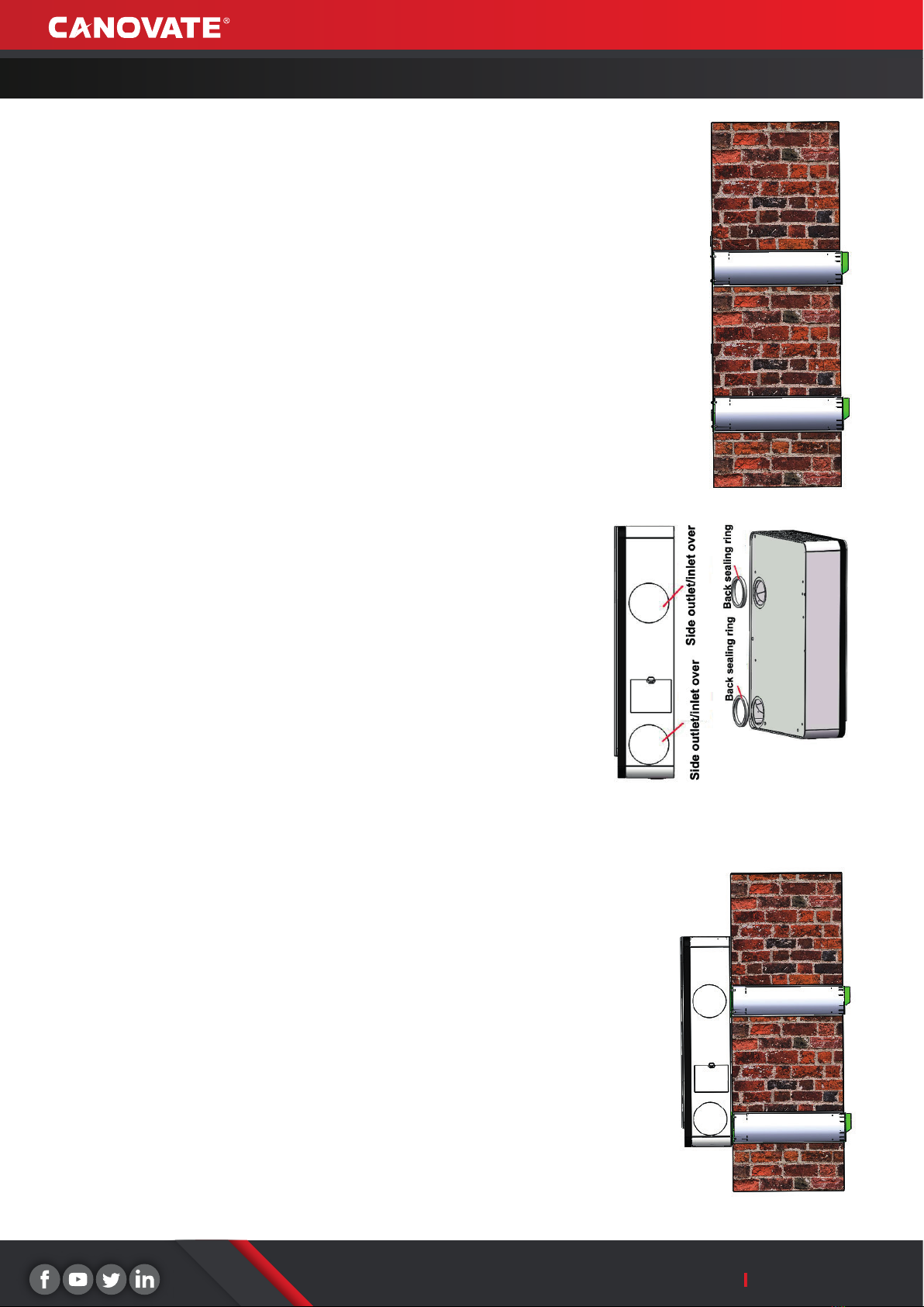
Installation Instructions
According to the site to choose suitable installation, Air inlet/outlet from back or from the side
1. Choose the suitable location on wall, mark the
OA inlet and EA outlet location, also mark the 5
xing holes of the installation panel on the wall
Attention; Ventilator bottom to the oor around 1.5 meters
Ventilator left and right side to the wall not less than 0.3 meter
2. To drill 2 holes on wall for fresh air inlet and exhaust air outlet, recommended size is
diameter 100mm, The 2 holes should face downward toward the outside to
prevent any rain water ingress. Recommended size for the 5 xing holes is
φ6x70mm, and input the 5 plastic bolt Jacket into the holes
Attention: The OA inlet and EA outlet holes size is according to the ICERA Hepa W accessories
(PVC pipes).
3. Connect the ange to the installation panel by M3X12 bolt and nut
4. According to the wall thickness, cut the suitable length of the PVC pipes, connect the PVC pipes to the anges and
also the OA inlet grille and EA outlet grille , please pay attention that the eave of the cover is at the top
Ventilator installation
Back installation
www.canovate.com [email protected]
10
Installation Instructions
5. To input the assembling ducts to the wall, and x the installation panel on wall by the
knock-on anchor bolt .
6. Seal the gap between wall and the PVC pipes by sealant from outdoor
7. Install the round covers on the side of the ventilator (installed already before
ex-factory), to cover the air inlet and outlet. Paste the 10mm seal rings to the
back of the air inlet and outlet
8. Hang the ventilator on the installation panel, user can adjust the 4 pieces
hanging screws on the back of the ventilator to suit the installation panel.
9. After the installation is completed, power on the ventilator
Table of contents
Popular Fan manuals by other brands

ELTA FANS
ELTA FANS H03VV-F installation guide

Hunter
Hunter 20714 Owner's guide and installation manual

Emerson
Emerson CARRERA VERANDA CF542ORB00 owner's manual

Hunter
Hunter Caraway Owner's guide and installation manual

Panasonic
Panasonic FV-15NLFS1 Service manual

Kompernass
Kompernass KH 1150 operating instructions


