Cantek JDT-65 Application guide

Operations
& Parts Manual
www.cantekamerica.com
Please ensure you have your serial number available when contacting us for parts or service.
Cantek America Inc. | 1.888.982.2683 | Parts: [email protected] | Service: service@cantekamerica.com
JDT65
Manual Dovetailer

- 1 -
Features
zIdeal for drawer production and furniture parts which require high quality dovetail joints.
zTenon and mortise depth are conveniently adjusted according to the thickness of work piece.
zEquipped with one four-sided template providing four types of pitches between dovetails.
SPECIFICATIONS
Model JDT-65 JDT-65S
Minimum work piece size 200 x 60 mm
Maximum work piece size 1500 x 420 mm
Minimum dovetail height 5 mm
Maximum dovetail height 18 mm
Minimum front thickness 7 mm
Maximum front thickness 60 mm
Minimum side thickness 7 mm
Maximum side thickness 60 mm
Number of spindles 1
Motor 1HP (1PH)
Spindle speed ( RPM) 18500 RPM
Center-to-center dovetail spacing
1", 1-1/2", 2", 2-1/2 "
5/8", 3/4", 1-1/4", 1-3/4"(Optional)
25, 40, 50, 80 mm (Optional)
16, 18, 32, 36 mm (Optional)
Table height from floor 1180 mm
Dust collection ports diameter front 2-1/2", rear 4"
Packing dimensions 105 x 79 x 160 cm
N.W. / G.W. 200 / 245 Kgs 150 / 195 Kgs
*All specification, dimensions and design characteristics are subject to change without prior notice.
IMPORTANTΚWhen ordering replacement parts, always give the model number, serial number of
the machine and part number. Also a brief description of each item and quantity desired.

- 2 -
1. Indication Template
2. Open-end Wrench 30mm
3. Hex Wrenches
4. Combination Wrenches
(17-19, 12-14, 11-13, 8-10)
5. Fence
6. Fixed Chasers
7. Grease Gun
1
2
3
5
67

- 3 -
Installation & Assembly
Tools required for assembly
forklift or hoist with straps/slings
14mm wrench (provided)
[NOTE: A socket set with ratchet wrench may
speed assembly]
1. Remove the four screws and flat washers
holding the machine to the pallet with a 14mm
wrench, as shown in Figure 1.
2. Place lifting straps through the two eyebolts at
the top of the machine (B, Figure 2). Using a
forklift or hoist, lift the machine off the pallet and
into its desired location. The Dovetailer should
be located in a dry area with sufficient lighting.
Leave plenty of space around the machine for
operations and routine maintenance work.
3. If desired, the Dovetailer can be further
stabilized by securing it to the floor, using lag
screws through the four holes at the bottom of
the cabinet.
4. A group of cords holds the headstock secure to
the machine frame to prevent it from moving
during shipping. These cords
should now be cut and removed (see Figure 3).
5. Exposed metal areas of the dovetailer (such as
the table, template bar, cylinder clamps, rods,
etc.) have been factory
coated with a protectant. This should be
removed with a soft cloth dampened with
kerosene or mineral spirits. Do not use an
abrasive pad. Do not let solvent contact plastic
or rubber parts as it may damage them.
Attaching Dust Hose
1. Slide the upper end of the hose over the chute
on the dust hood (Figure 4).
2. Tighten the hose clamp with the attached
screw, using a flat head screwdriver.
Fi
g
ure 4
Fi
g
ure 3
Fi
g
ure
2
Fi
g
ure 1

- 4 -
Installing Dust Chute
Remove the four socket head cap screws at the rear of
the cabinet, using a 4mm hex wrench. Place the 4”
diameter dust chute (Figure 5) over the hole, and
re-insert and tighten the four socket head cap screws.
Dust Collection
The use of a dust collection system is strongly
recommended for this machine. It will help you’re your
shop clean as well as minimize any health risks caused
by wood dust. Make sure your dust collector has a
capacity of at least 500 cubic feet per minute (CFM).
Connect the intake hose of your dust collector to the 4”
diameter dust chute at the back of the cabinet (Figure 5).
Grounding Instructions
. Electrical connections must be
made by a qualified electrician in compliance with all
relevant codes. This machine must be properly
grounded to help prevent electrical shock and
possible fatal injury.
This machine must be grounded. In the event of a
malfunction or breakdown, grounding provides a path of
least resistance for electric current to reduce the risk of
electric shock.
Improper connection of the equipment grounding
conductor can result in a risk of electric shock. The
conductor, with insulation having an outer surface that is
green with or without yellow stripes, is the equipment
grounding conductor. If repair or replacement of the
electric cord or plug is necessary, do not connect the
equipment-grounding conductor to a live terminal.
Check with a qualified electrician or service personnel if
the grounding instructions are not completely
understood, or if in doubt as to whether the tool is
properly grounded. Use only three wire extension cords
that have three-prong grounding plugs and three-pole
receptacles that accept the tool’s plug.
Repair or replace a damaged or worn cord immediately.
Make sure the voltage of your power supply matches the
specifications on the motor plate of the Dovetailer.
Figure 5

- 5 -
230 Volt Operation
As received from the factory, the JDT-65
Dovetailer is designed to run on 230 volt power
only. You may either connect a UL/CSA listed
230V plug (similar to the one shown in Figure 6)
or “Hard-wire” the machine directly to a control
panel. If hard-wired to a panel, make sure
disconnect is available for the operator. The
dovetailer must comply with all local and national
codes after being wired.
1. If it is to be hard-wired, make sure the fuses
have been removed or the breakers have been
tripped in the circuit to which the dovetailer will
be connected. Place a warning placard on the
fuse holder or circuit breaker to prevent it being
turned on while the machine is being wired.
2. Refer to “Electrical Connections” for connecting
the motor leads.
3. The Dovetailer with a 230 volt plug should only
be connected to an outlet having the same
configuration. No adapter is available or should
be used with the 230 volt plug.
Air Connection
Connect the air supply hose to the coupling on
the air unit (Figure 7).
Even after the air has been
turned off to the machine, there may be
residual air inside the lines, and the clamping
cylinders can still provide a hazard to fingers.
After shutting off the air, always bleed
residual air from the system by pushing the
relief valve pin at the bottom of the air cup,
shown in Figure 7. Keep the relief valve open
until all air in the system has been removed.
Figure 6
Figure 7
THREE-PRONG
GROUNDING PRONG
GROUNDED OUTLET

- 6 -
Adjustments
Disconnect machine from
power source, shut off air supply and bleed
residual air from system, before making
adjustments. Failure to comply may cause
serious injury.
Clamping Cylinders
The workpieces are clamped to the table by
pneumatically operated aluminum cylinders (A,
Figure 8). Each cylinder has its own air on/off
lever. Simply turn the lever (B, Figure 8) to “on”
position to activate the cylinder; the cylinder will
respond immediately by clamping the workpiece
against the table.
Always keep fingers out of
the way of clamping cylinders. Failure to comply
may cause serious injury.
Both vertical and horizontal clamping cylinders can
be adjusted to match the thickness of your
workpieces. To change the thickness capacity of
the clamping cylinders, proceed as follows:
1. To increase the clamping capacity, loosen the top
two hex nuts (A and B, Figure 9) on the stud at the
end of the holder bracket, with a 30mm wrench. Do
the same for the stud at the opposite end of the
holder bracket.
2. Tighten the lower hex nut (C, Figure 9). You can do
this without a wrench. This will raise the holder
bracket. Do this incrementally on both studs until
the desired height is reached. When finished,
tighten top hex nuts (A & B, Figure 9) on both studs
with the wrench.
NOTE: Make equal adjustment on both studs at each
end of the holder bracket to ensure the clamps are
parallel to the table. To check this, measure from the
bottom edge of the holder bracket down to the table.
Measure at each end of the holder bracket – the
measurements should be equal. Figure 9 shows the
horizontal clamping assembly - the procedure is
identical for the vertical clamping assembly.
3. To decrease the clamping capacity, back off the
lower hex nut (C, Figure 9) and tighten the top hex
nut (A, Figure 9). This will lower the holder
bracket.
4. When finished, tighten the lower hex nut (C)
against the holder bracket, and bring hex nut (A)
down against hex nut (A).
Figure 8
Figure 9
Figure 10
A
B

- 7 -
The clamping cylinders can also be adjusted laterally for
better support of workpieces with differing widths.
Simply loosen the locking handle (Figure 10) and slide
the clamping cylinder to position. Re-tighten locking
handle.
Clamping Pressure
The pressure exerted by the cylinder clamps against the
workpiece can be adjusted at the air regulator, shown in
Figure 11. The hardness or softness of the wood will
determine the amount of clamping pressure desired.
Enough pressure should be used to prevent the
workpiece from slipping during operations. Forty (40) psi
is suitable for clamping most wood; going above that is
not recommended.
To change the clamping pressure, pull up on the knob
(A, Figure 11) and rotate it; clockwise to increase
pressure, counterclockwise to decrease pressure. The
attached needle indicator (B, Figure 11) shows the air
pressure. Lock the setting by pushing the knob (A,
Figure 11) back down.
Locking Handles
All locking handles, such as those shown in Figure 10,
can be rotated out of the way if they interfere with other
machine parts. Simply lift straight out on the locking
handle and rotate it, then release, making sure it seats
properly.
Template Bar
The four-sided template bar, shown in Figure 14, will
allow you to create “half-blind” dovetails, where the
dovetails are visible on only one side of the joint. It will
create dovetails in one of four different “pitches” or
centerlines. The available pitches are 1”, 1-1/2”, 2”and
2-1/2”. To change the pitch of a dovetail cut, proceed as
follows:
1. First notice how the notches on the template bar are
grouped toward the right side of the machine. The
template bar should always be oriented in this
fashion.
2. Release one end of the spring on the left side of the
headstock (Figure 12) and pull the headstock forward
until the tracer pin (Figure 13) is clear of the template
bar.
3. Loosen and remove the locking handles on each end
of the template bar (Figure 14).
4. Pull out the template bar, flip it to the desired side,
and then reinstall it.
NOTE: The pitch dimension is inscribed on each side of
the template bar. The side of the template bar
that you have chosen should face downward
when mounted on the machine.
5. Insert and tighten both locking handles.
Figure 11
Figure 12
Figure 12
Figure 13

- 8 -
6. Push the headstock back and re-connect the spring
(Figure 12).
You must now also shift the indication template (Figure
14). See “Indication Template.”
Indication Template
Because the tracer pin is not easily observed while the
machine is in operation, the indication template (A,
Figure 15) provides the operator with a visual record of
the progress of the ”hidden” tracer pin. The bracket (B,
Figure 15) slides in and out of the notches on the
indication template, echoing the tracer pin as it slides
in and out of the notches on the template bar below.
The pitch of the indication template must match the
pitch of the template bar. Therefore, when turning the
template bar for a new pitch, you must also change the
indication template.
1. First notice how the notches on the indication
template are grouped toward the right side of the
machine. The indication template should always be
oriented in this fashion.
2. Remove the socket head cap screw (C, Figure 15)
at each end of the indication template, with a 5mm
hex wrench.
3. The indication template that came installed on your
machine contains the 1” and 2” pitch. The other
indication template has the 1-1/2” and 2-1/2” pitch.
Either flip the indication template, or replace it with
the other one as needed, to match the pitch of the
template bar.
4. Re-insert and tighten the socket head cap screws
(C, Figure 15).
Fixed Chaser
The fixed chaser (Figure 16) provides a support on
which the workpieces rest. The spacing between the
“fingers” of the fixed chaser allows clearance for the
cutter.
The 40-050 Dovetailer comes standard with three fixed
chasers at 2”, 2-1/2”and 3” pitches. (Pitch is
thedistance between the centers of the ”fingers” see
Figure 17).
NOTE: If you wish to use the 1-1/2”or 2-1/2”pitch on
the template bar, you must replace the fixed chaser on
the machine with one of the others provided.
Figure 16
Figure 14
Figure 15

- 9 -
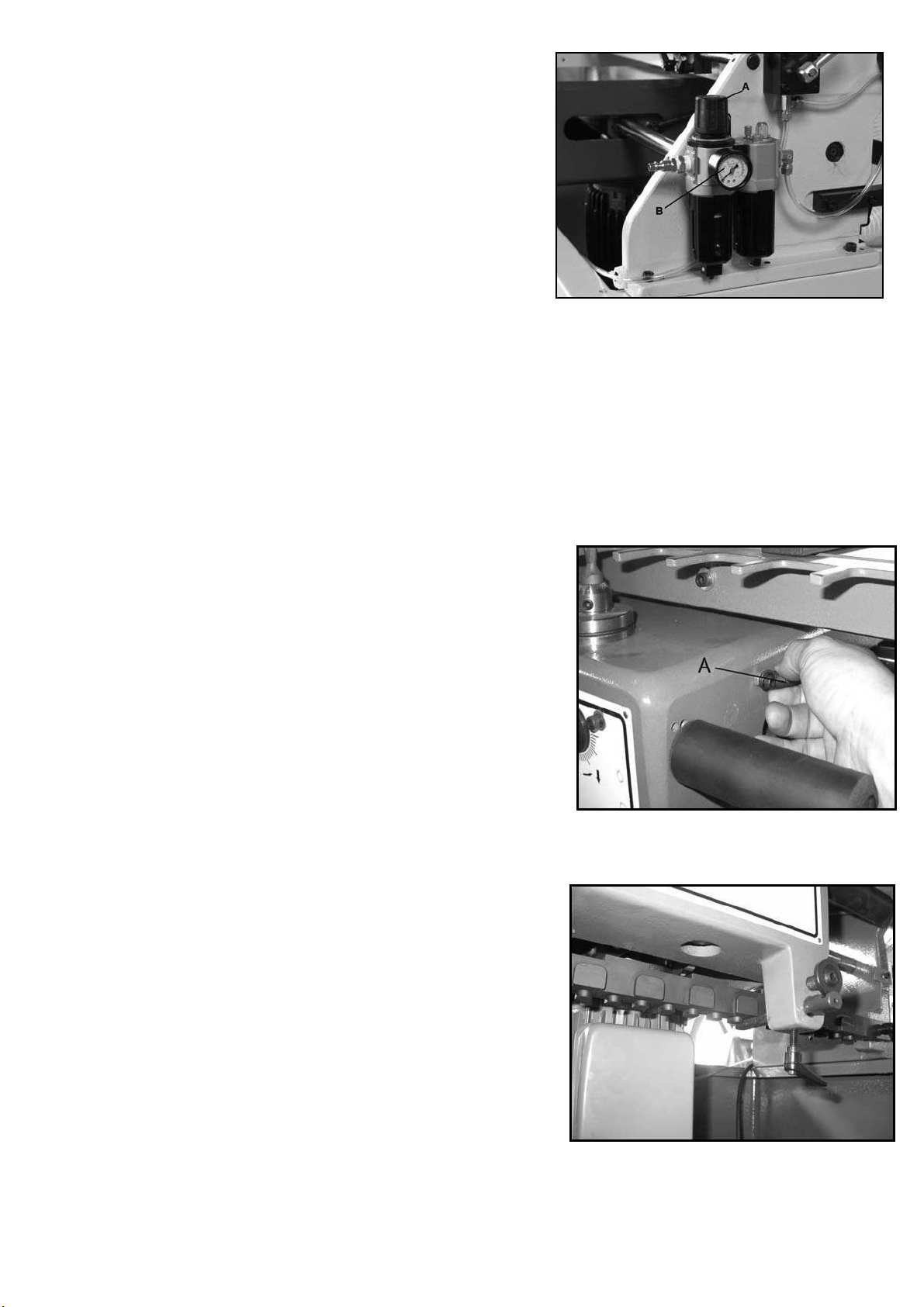
1. To replace the fixed chaser, remove the three M6
socket head cap screws and flat washers, using a
5mm hex wrench as shown in Figure 17. Remove the
fixed chaser.
2. Install the new fixed chaser and make sure it is level
with the main table.
3. Re-insert and tighten the socket head cap screws
against the flat washers.
After mounting the fixed chaser, make sure it will
correspond to your chosen pitch on the template bar.
With the machine power off, slide the headstock across
the length of the fixed chaser, allowing the cutter to
move in and out of the spaces. If there is any
interference between the cutter and one of the “fingers”
on the fixed chaser, then try a different fixed chaser, or
change the pitch of the template bar.
Horizontal and Vertical Fences
The workpieces will lie flush against the fences during
cutting to ensure squareness. Two buffer pads made of
polyethylene material are mounted to the fences - these
provide a “chip breaker” effect to prevent chip-out on the
left edges of the workpieces. They are designed so the
cutter can bite into them without any damage to the
cutter.
To adjust these fences, proceed as follows:
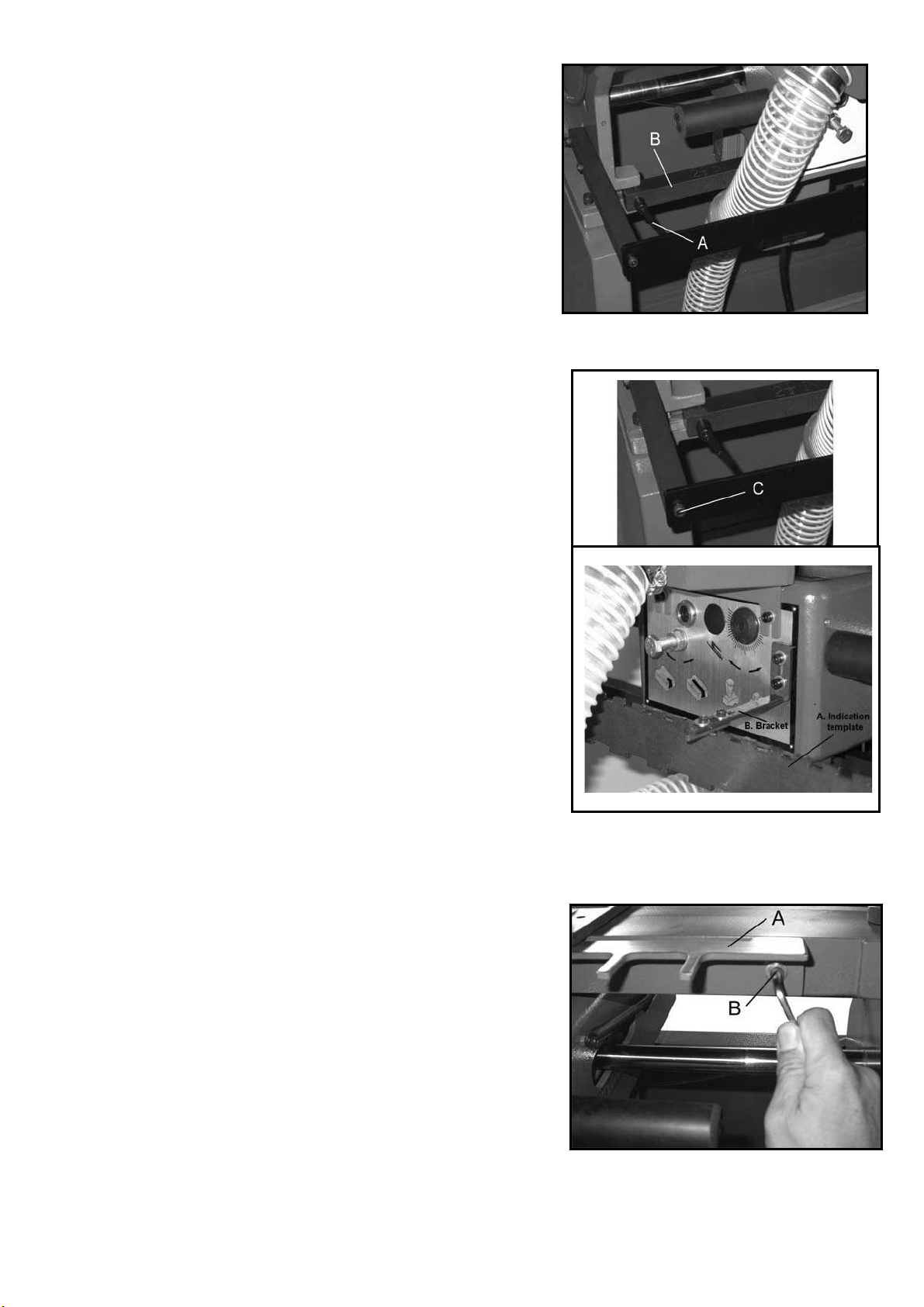
1. Place your FRONT/BACK workpiece on the
horizontal table and against the fence/buffer pad.
Move the headstock to the left edge of the workpiece,
then slide it to the right, allowing the tracer pin to slide
just a little into the template recesses, while observing
through the dust hood window the progress of the
cutter. This will give you an idea where the cuts will be
made and how they will be spaced across the width of
the workpiece.
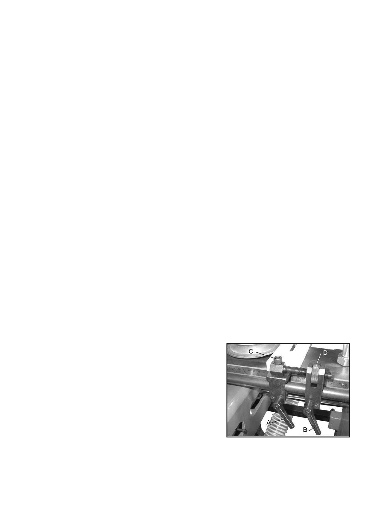
2. For broad movement of the horizontal fence, loosen
both locking handles on the horizontal fence (A and B,
Figure 17) and slide the horizontal fence into position.
Tighten both locking handles (A & B, Figure 17).
3. There is also a micro adjustment on the horizontal
fence; loosen locking handle (A, Figure 17), but leave
locking handle (B) tight. Loosen the screw rotate the
knurled knob (D, Figure 17) as needed for precise
positioning of the horizontal fence.
4. When finished, locking handle (A, Figure 17).
Fingure 17

- 10 -
NOTE: Make sure locking handles (A & B,
Figure 17) will not interfere with the headstock
during operation.
5. Continue to check the spacing by sliding the
headstock across, until the dovetail cuts will be
distributed evenly across the width of the
workpiece. NOTE: This is an approximate
method of determining by eye where to place the
workpiece. A scale in inches and millimeters is
mounted to both horizontal and vertical tables, if
you need more precise measurements for the
location of the dovetail cuts.
6. Again, make sure the locking handles on the
horizontal fence (A & B, Figure 17) aretightened.
The position of the horizontal fence will now be
used as the basis for locating the vertical fence.
7. Loosen the locking handle on the vertical fence.
8. As noted, the position of the horizontal fence will
affect the position of the vertical fence. Therefore,
if you are making a drawer that has a bottom
groove, the vertical fence should be set so that
the bottom groove in the drawer piece to be
tenoned will go through the center of a tail. That
means the bottom groove of the mortised piece
will go through the center of a mortise. This will
prevent the groove from being visible on the
outside of the assembled drawer.
ImportantΚTo make proper dovetail cuts, the two
fences must always be offset from each other by
half the pitch of the template bar. That is, offset 1/2”
when using the one-inch template; 3/4” when using
the 1-1/2 template; 1” when using the two-inch
template, and 1-1/4” when using the 2-1/2 inch
template. The measuring scales on the horizontal
and vertical tables are marked in 1/16” increments
and millimeters.
9. Line up the vertical fence with the horizontal
fence, then offset the vertical fence by exactly
half the pitch of the template bar. See Figure 18.
10. This adjustment will cause the vertical work
piece to be slightly offset to the right of the
horizontal piece (as viewed from front of
machine), thus ensuring the dovetails will
correspond when the two pieces are assembled.
11. Tighten the locking handle on the vertical fence.
Figure 18
(view from rear of machine)

- 11 -
There are a total of four fences on the 40-050
Dovetailer - two vertical and two horizontal. These
allow two sets of workpieces to be cut at the same
time. If this is desired, position the other two fences in
the same manner as the first two fences, remembering
again to offset the vertical fence by half the pitch.
Buffer Pads
The polyethylene buffer pads, shown in Figure 18,
have slots through which they are secured to the
fences by screws. These buffer pads can be
re-positioned if needed.
To adjust a buffer pad, loosen the two hex cap screws
(shown in Figure 18) with a 13mm wrench. Slide the
buffer pad as necessary. Retighten both hex cap
screws when finished.
Cutter Height
This adjustment will change the height of the tail on the
tenon (male) cut, and how deep the mortise (female)
cut goes into the thickness of the workpiece.
1. Disconnect machine from power source.
2. Loosen the spindle lock screw (Figure 19) by turning
it counterclockwise with a 6mm hex wrench.
3. Turn the spindle height adjustment screw (Figure 19)
with a 5.5mm hex wrench, either clockwise to raise
the cutter (increase the cutter depth), or
counterclockwise to lower the cutter (decrease the
cutter depth).
4. Tighten spindle lock screw by turning it clockwise.
Mortise Depth
This adjustment ensures that the side pieces of your
drawer will remain flush with the front and back pieces
of the drawer. The correct fit will have the sides flush
with the front and back of the drawer, without showing
any of the mortise cut on the inside of the drawer.
The mortise depth adjustment bolt, shown in Figure 19,
limits how far forward the headstock will go, and thus
limits the length of your mortise cut.
1. Disconnect machine from power source.
2. Loosen the hex nut on the mortise depth adjustment
bolt (Figure 19) by turning the hex nut
counterclockwise with a 17mm wrench.
Figure 19

- 12 -
3. To decrease the depth of the mortise (female) cut,
turn the bolt clockwise. To increase the depth of
the mortise cut, turn the bolt counterclockwise.
4. Re-tighten the hex nut.
Thickness of Tenon Cut
To adjust the thickness of the tenon (male) cuts, you
will change the depth of the tracer pin (A, Figure 20).
1. Disconnect machine from power source.
2. Loosen the locking handle (B, Figure 20).
3. Insert a 5.5mm hex wrench into the end of the
adjustment screw (C, Figure 20) and turn the
adjustment screw as needed. To decrease the
thickness of the tenon cut, turn the adjustment
screw counterclockwise. To increase the thickness
of the tenon cut, turn the adjustment screw
clockwise.
4. Tighten locking handle (B, Figure 20).
Tightness of Mortise / Tenon Fit
A proper dovetail fit should be snug with no gaps
showing, but not overly tight as glue must later fill the
joints. If the cuts seem correct, but the joint is simply
too tight, or the joint is too loose, proceed as follows.
1. Disconnect machine from power source.
2. Remove the dust hood from the front of the
headstock. Release one end of the spring on the
headstock (see Figure 12) and pull the headstock
away from the machine until the cutter becomes
more accessible.
3. You will notice the cutter, shown in Figure 21, is
slightly off center of the spindle. The spindle is
eccentric and allows the cutter to be turned to a
different position on the spindle.
The cutter is very sharp!
Use caution when working with or around it.
4. Loosen both set screws on the spindle (Figure 21
by turning them counterclockwise with a 4mm hex
wrench.
5. A scale is located just above the cutter, with a plus
(+) and minus (-) sign. Moving the cutting edge of
the cutter toward the plus (+) side of the scale will
increase the size of the mortise cut and decrease
the size of the tenon cut. Moving the cutting edge
of the cutter toward the minus (-) side will decrease
the size of the mortise cut and increase the size of
the tenon cut.
Figure 20
Figure 21

- 13 -
NOTE: One notch of the scale equals 1mm.
6. With your fingers on the shank portion of the
cutter, carefully rotate the cutter toward the plus
(+) or minus (-) position as needed.
7. When satisfied with the adjustment, tighten both
set screws firmly.
8. Re-attach the spring on the headstock, and
re-install the dust hood.
Drive Belt Tension
The tightness of the belt that drives the spindle has
been adjusted at the factory. Further adjustment
may be necessary after the machine receives some
use, as the belt may stretch slightly during the
“breaking in” process.
Belt tension can be adjusted by a socket head cap
screw at the rear of the headstock (Figure 22)
which slides the motor toward or away from the
spindle. To tighten the belt, rotate this cap screw
clockwise with a 6mm hex wrench. To loosen the
belt, rotate the cap screw counterclockwise. The
belt should be just tight enough to prevent it slipping
on the spindle during operation.
Replacing cutter
The cutter is very sharp; use caution when working
with or around cutter. Disconnect machine from
power source! Failure to comply may cause serious
injury.
1. To replace the cutter, loosen both set screws
(Figure 21) and carefully pull up on the cutter until
it is free from the spindle.
2. Slide the new cutter down into the spindle, and
align the cutting edge with your previous setting
on the spindle scale.
3. Tighten both set screws.
Oil Output
Oil is distributed through the air lines for constant
lubrication of the clamping system. The oil output
can be adjusted by rotating the oil regulator knob
(A, Figure 23). Turn the knob counterclockwise to
increase oil output, clockwise to decrease oil
output. The level of oil should be checked
occasionally and re-filled as necessary. A minimum
level is marked on the window of the oil cup (C,
Figure 23). Refill by removing the screw (B, Figure
23) and pouring oil into the fill hole. When finished,
re-install screw (B, Figure 23). Use standard air tool
oil. This is available from your local distributor, or
can be found in most hardware and tool stores.
Figure 22
Figure 23

- 14 -
Operation
NOTE: The following are basic dovetailing procedures
as they apply to this machine, and are not intended to
be a full course of instruction in making dovetails.
Refer back to the terminology on page 2 if needed.
The Dovetailer can be used to make joints in drawers,
boxes, cabinets, etc. Instructions in this manual are
based upon making a drawer consisting of FRONT and
BACK pieces, and two SIDE pieces. FRONT and
BACK pieces are placed horizontally on top the
machine table; SIDE pieces are placed vertically.
No matter the project, prevent mistakes by laying out
the pieces beforehand according to how they will be
assembled. Place them with the inside facing up, and
label the mating edges.
Before cutting on what is to be the finished piece, the
operator should make test cuts on scrap wood to make
sure all settings and adjustments are correct.
IMPORTANT: Make sure the workpiece has been cut
square before making dovetails. An out-of-square
workpiece will result in poor dovetail joints.
1. Check that all the following has been set correctly
(See “Adjustments” above):
¾proper pitch of Template Bar
¾proper Indication Template
¾Vertical and Horizontal Fence positions
(offset from each other by half the pitch of the
template bar)
¾height of Clamping Cylinders for workpiece
thickness
¾proper Fixed Chaser, with no cutter
interference
¾height of Cutter
2. Move the headstock all the way to the right and out
of the way.
3. Connect the air supply and the electrical power to
the machine.
Keep fingers clear of clamping
cylinders.
4. Place the drawer RIGHT SIDE against the vertical
table and on top the fixed chaser. The RIGHT SIDE
should be flush against the fence, with the bottom
groove facing outward and opposite the fence
(Figure 24).
Figure 24

- 15 -
5. Activate the clamping cylinder in front of the RIGHT
SIDE workpiece.
6. Place the drawer BACK on the horizontal table, and
against the horizontal fence. Slide it flush against the
RIGHT SIDE workpiece. The bottom groove on the
BACK should face downward and opposite the
fence. See Figure 25.
7. Activate the clamping cylinder above the BACK
workpiece.
8. The BACK is now butting against the RIGHT SIDE
so they are flush, with the RIGHT SIDE overlapping
the edge of the BACK. Both workpieces should be
firmly and evenly against the fences.
9. Turn on the machine at the switch, and slide the
headstock to the left edge of the workpiece. Move
the cutter in sequence, left to right, allowing the
tracer pin to move in and out of the template slots.
See Figure 26. You can watch the progress of the
cutter through the window of the dust hood.
NOTE: Do not rush the cut; allow the cutting unit to
do the work.
10. When finished, slide the headstock out of the way
and unclamp the workpieces by turning the
clamping cylinder levers to “off”.
11. Fit the BACK and RIGHT SIDE together and
examine the joint. If the joint is not satisfactory,
make any needed corrections to your settings as
explained under “Adjustments.” If the joint is
satisfactory, proceed with the next cut as follows.
12. Insert the LEFT SIDE piece and clamp it in vertical
position and against the fence.
(NOTE: The bottom groove on the LEFT SIDE will
face outward and toward the fence.)
13. Turn the BACK 180 degrees and clamp it in the
horizontal position against the fence. (NOTE: The
bottom groove on the BACK workpiece will still be
face down, but toward the fence.)
14. Make the cut, and then continue the dovetailing
procedure with the FRONT piece, making
cuts until all four joints of the drawer have been cut.
TIP: When using drawer side widths that are not “whole
inch” sizes, you may wish to gauge off the top of the
drawer rather than the bottom when placing
workpieces in the machine. Doing this will improve the
look of the drawer by providing a full tenon near the top
of the drawer and the half-tenon will end up at the
bottom. See Figure 27.
Figure 25
Figure 26
Figure 27

- 16 -
Preventing Chip Out
As noted previously, when the SIDE and
FRONT/BACK pieces are inserted into the machine,
they are offset a bit so they’ll match correctly when
assembled. In other words, the SIDE will rest slightly
to the right of the FRONT/BACK in the machine. This
leaves the right edge of the SIDE exposed without
the “chip breaker” effect that the FRONT/BACK
provides for the rest of the SIDE (see Figure 28). This
may result in an unsatisfactory cut at the edge of the
SIDE.
This problem is resolved simply by taking a two
inch-plus wide “back-up” board, of the same
thickness as the workpiece, and clamping it
horizontally next to the FRONT/BACK piece, so that it
backs up the exposed edge of the SIDE, as shown in
Figure 28. You can use this piece over and over
again.
Dovetails in Plywood
Because plywood handles a bit differently than solid
stock, here are some tips to follow:
1. When using plywood, the layers tend to be more
fragile. Therefore, the operator should keep the
movement of the cutting unit consistent and
proceed relatively slowly.
2. On the rounded arcs of the tenon cuts, you may
lose a bit of the top layer. This is to be expected
with plywood, and does not affect either the look or
the strength of the assembled dovetail joint.
Rather, the strength of the dovetailed corner comes
from the flat side of the tenons.
3. Plywood has a tendency to chip out on exposed
edges. A back-up board may be necessary (see
Figure 28).
Figure 28
(view from rear of machine)
Maintenance
Before doing
maintenance on the machine, disconnect it
from the electrical supply and the air supply,
and release any residual air from the lines.
Failure to comply may cause serious injury.
If the power cord is worn, cut, or damaged in
any way, have it replaced immediately.
The horizontal and vertical tables and other
exposed metal parts should be kept clean and
free of rust. A coat of paste wax will help protect
the tables from tarnishing.
After each day’s use, brush or blow out dust and
debris from the cutter, table, motor, etc.
Keep the clamping cylinders clean to prevent
debris adhering to them, which can scar
workpieces.
Keep clean the travel rods upon which the
headstock slides.
Lubrication
The linear bushings by which the headstock
travels on the rods are pre-lubricated and
sealed; they do not require additional
lubrication.
The spindle unit is also sealed and requires
no lubrication.
Occasionally check the oil level in the oil
regulator cup (see Figure 24). Add more oil as
needed. Use standard air tool oil.

- 17 -
List of Parts for Dovetailer
D65-01A
PART NO. REF NO. DESCRIPTION SPECIFICATION QTY
D6501A-01 D65-1010 WORK TABLE 1
D6501A-02 D65-1050 BASE GUIDE ROD 2
D6501A-03 BB HEX. SOCKET SET SCREW M6x16 4
D6501A-04 SWITCH BRACKET 1
D6501A-05 FW FLAT WASHER M6x16x2 2
D6501A-06 BB HEX. SOCKET CAP SCREW M6x16 2
D6501A-07 SWITCH 1HP.230V 1
D6501A-08 BB HEX. SOCKET CAP SCREW M4x12 2
D6501A-09 SCALE 1
D6501A-10 FIXED CHASER 1
D6501A-11 FIXED CHASER 1
D6501A-12 FIXED CHASER 1
D6501A-13 FW FLAT WASHER M6x16x2 3
D6501A-14 BB HEX. SOCKET CAP SCREW M6x25 3
D6501A-15 TEMPLATE BAR 1
D6501A-16 AL LEVER M6x35 2
D6501A-17 LINK 2
D6501A-18 SPRING WASHER M6x10x1 4
D6501A-19 BB HEX. SOCKET CAP SCREW M6x35 4
D6501A-20 INDICATION TEMPLATE 1
D6501A-21 INDICATION TEMPLATE 1
D6501A-22 BB HEX. SOCKET CAP SCREW M6x16 2
D6501A-23 FENCE SLIDING BAR 2
D6501A-24 BB HEX. SOCKET CAP SCREW M6x10 2
D6501A-25 FENCE BASE 4
D6501A-26 BB HEX. SOCKET CAP SCREW M6x10 4
D6501A-27 AL LEVER M8x25 4
D6501A-28 FENCE 4
D6501A-29 FW FLAT WASHER M8x24x3 8
D6501A-30 HEX. SCREW M8x20 8
D6501A-31 ADJ. SCREW 1
D6501A-32 BB HEX. SOCKET CAP SCREW M8x30 1
D6501A-33 D75-4150 ADJ, NUT 1
D6501A-34 ADJ. SCREW SEAT 1
D6501A-35 BB HEX. SOCKET CAP SCREW M6x10 1
D6501A-36 AL LEVER M8x25 1

- 18 -
List of Parts for Dovetailer
D65-01A
PART NO. REF NO. DESCRIPTION SPECIFICATION QTY
D6501A-37 D65-1380 BUFFER PAD 2
D6501A-38 FW FLAT WASHER M6x13x1 2
D6501A-39 BB HEX. SOCKET CAP SCREW M6x20 2
D6501A-40 POINTER 1
D6501A-41 FW FLAT WASHER M5 1
D6501A-42 BB HEX. SOCKET CAP SCREW M5x10 1

- 19 -
List of Parts for Dovetailer
D65-02A
PART NO. REF NO. DESCRIPTION SPECIFICATION QTY
D6502A-01 ʳSPINDLE ASS'Y ʳ1
D6502A-02 D75-2110 BEARING HOUSING ʳ1
D6502A-03 BG6005 BEARING 6005 TB. T63 1
D6502A-04 D75-2120 BEARING LOCK PIECE ʳ1
D6502A-05 D75-2100 SPINDLE ʳ1
D6502A-06 BS HEX. SOCKET SET SCREW M8x10 1
D6502A-07 D75-2130 BUSHING ʳ1
D6502A-08 DS1.DS2 SPRING ʳ1
D6502A-09 GB6005 BEARING 6005 TB. T63 1
D6502A-10 D75-2240 BEARING LOCK PIECE ʳ1
D6502A-11 BB GREASE NIPPLE M6 1
D6502A-12 D65-1060 SPINDLE BASE ʳ1
D6502A-13 D65-1090 SPINDLE ADJ. GEAR ʳ1
D6502A-14 FW FLAT WASHER M8x24x3 1
D6502A-15 BA HEX. HD. SCREW M8x20 1
D6502A-16 D65-1100 STOP BLOCK ʳ1
D6502A-17 D65-1110 BUSHING ʳ1
D6502A-18 BB HEX. SOCKET CAP SCREW M8x65 1
D6502A-19 D65-1190 FACE PLATE ʳ1
D6502A-20 PG CAP ĭ22 1
D6502A-21 FW FLAT WASHER M10x20x2 1
D6502A-22 HN HEX. NUT M10 1
D6502A-23 BA HEX. HD. SCREW M10x150 1
D6502A-24 D65-1140 MODEL PIN ʳ1
D6502A-25 D65-1130 ADJ. SCREW ʳ1
D6502A-26 AL LEVER M6x25 1
D6502A-27 D65-1080 SHAFT ʳ2
D6502A-28 BS HEX. SOCKET SET SCREW M6x12 4
D6502A-29 D65-1070 SLIDER ʳ1
D6502A-30 LM BEARING LM16UUT 4
D6502A-31 SL SEAL KC 16x28x7 4
D6502A-32 PR CIRCLIP R28 4
D6502A-33 LM BEARING LM25UUT 4
D6502A-34 SL SEAL KC 25x40x7 4
D6502A-34 PR CIRCLIP R40 4
D6502A-36 HN HEX. NUT M5 1
This manual suits for next models
1
Table of contents
Other Cantek Industrial Equipment manuals