Cantek P24HV Application guide

Operations
& Parts Manual
www.cantekamerica.com
Please ensure you have your serial number available when contacting us for parts or service.
Cantek America Inc. | 1.888.982.2683 | Parts: [email protected] | Service: service@cantekamerica.com
P24HV
24” Planer

TABLE OF CONTENTS
1. SPECIFICATIONS AND ACCESSORIES AND MAMES OF OPERATING PAPTS ...................................................... 1-2
1-1 Specifications ...................................................................................................................................................................................................... 1
1-2 Accessories .......................................................................................................................................................................................................... 1
1-3 Names of operating parts .................................................................................................................................................................................... 2
2. INSTALLATION ................................................................................................................................................................................................ 3
3. PREPARATION FOR OPERATION ...................................................................................................................................................... 3-4
3-1Inspection .............................................................................................................................................................................................................. 3
3-2Power Source wiring ............................................................................................................................................................................................ 3
3-3Lubrication ............................................................................................................................................................................................................ 3
3-4Safety ................................................................................................................................................................................................................. 3-4
4. MAINTENANCE ................................................................................................................................................................................................ 4
4-1General maintenance ............................................................................................................................................................................................ 4
4-2Lubrication ............................................................................................................................................................................................................ 4
5. MACHINE ADJUSTMENT ...................................................................................................................................................................... 5-10
5-1 Work table ........................................................................................................................................................................................................ 5-6
5-2 Infeed roll ......................................................................................................................................................................................................... 6-7
5-3Chip breaker ......................................................................................................................................................................................................... 7
5-4 Outfeed Roll ........................................................................................................................................................................................................ 7
5-5Pressure Bar .......................................................................................................................................................................................................... 8
5-6 Table Rolls........................................................................................................................................................................................................... 8
5-7 Test Cutting ...................................................................................................................................................................................................... 8-9
5-8 Knife installation ............................................................................................................................................................................................ 9-10
6. PART LIST.....................................................................................................................................................................................................11-39

1
1. SPECIFICATIONS AND ACCESSORIES AND MAMES OF OPERATING PAPTS
1-1 Specifications
Capacity
Max. width of work piece
630mm (24")
Max. thickness Of work piece
203mm (8")
Max. depth Of cut
8mm (5/16")
Min.
length Of work piece 200mm (8")
Cutterhead
Number of knives
3pcs
Diameter
80mm (3-1/8")
Cutting Circle
84mm (3-5/16")
Speed
4800RPM
Table Size
Width
660mm (25-1/4")
Length
713mm (28")
Feed Rolls
Infeed (sectional)
76mm-one (3")
Outfeed (solid)
60mm-one (2-3/8")
Table roll (solid)
68mm-two (2-11/6")
Feed Rate
8MPM (one speed)(26.3FPM)
Overall dimension (L x W x H)
1208 x 762 x 1136mm (47.5 x 30 x 45")
Packing dimension (L x W x H)
1380 x 800 x 1200mm (54 x 32 x 48")
Net weight
450kgs (992lbs)
Gross weight
550kgs (1213lbs)
1-2Accessories
Standard: Knife 1 set
Adjusting Spanner 1 set
Service Manual 1 set
Dust Hood 1pc

2
1-3 OPERAING PARTS
1. P24.01 BASE DEPT
2. P24.02 WORK TABLE
3. P24.03 UPPER DEMP
4. P24.04 GEAR DEPT
5. P24.05 ELECTRIC DEAR
6. P24.06 SIDE FRAME DERT

3
2. INSTALLATION
Mount machine on a solid foundation, preferably a concrete floor. The machine area should be clean, dry well ventilated, and well lighted.
Since planers can create noise problems, the site selection should be one which minimizes reverberant sound from walls, ceilings and other
equipment. Electricals should be installed so that they are protected from damage and exposure. Be sure to properly ground the machine
frame.
3. PREPARTION FOR OPERATION
3-1 Inspection
A. Clean protective coating form all areas and lubricate parts.
B. Before putting power on the machine, check that all screws are tight, that all mechanical functions work freely and that the cutterhead
turns freely without knife contact with the chipbreaker& pressure bar, periodic or regular inspections are required to insure that the
machine is in proper adjustment, that all screws are tight, that belts are in good condition, that dust has not accumulated in the electrical
enclosures, and that there are no loose or worn electrical connections.
3-2 Power source wiring
A. Check the motor and switch wiring diagram for proper voltage connections before applying power to the machine.
B. Connection wires both with electric connection box and power source, the earth wires also must be connected. (green line)
C. After wire connection is complete, turn the main drive motor on momentarily to check for proper direction of rotation.
D. Run the machine without cutting for a short period of time to check that all powered functions are operating properly.
3-3 Lubrication
Supply oil to all the necessary position.
3-4 Safety
A. Grounding of the planer: Make certain that the machine frame is electrically grounded.
B. Eye safely: Wear an approved safety shield, goggles, or glassed to protect eyes when operating the planer.
C. Personal protection: Before operating the machine, remove, tie ring, watch and other jewelry and roll up sleeves above the elbows.
Remove all loose clothing and confine long hair. DO NOT WEAR GLOVES.
D. Work area: Keep the floor around the machine clean and free of scrap material, sawdust, oil or grease and tools before starting a cut.
Make certain the work area is well lighted and that a proper exhaust system is used to minimize dust. Provide for adequate work space
around the machine.
E. Guards: Keep the machine guards in place at all times when the machine is in use. If removed for maintenance purpose, use extreme
caution and replace the guards on completion of the maintenance task before using the planer. DO NOT OPERATE THE MACHINE
WITH THE GUARDS OFF.
F. Do not over reach: Maintain a balanced stance and keep your body under control at all times. Do not over reach.
G. Maintain tools in to condition: Keep tools sharp and clean for safe and best performance. Dull tools increase noise levels and can cause
kickbacks and glazed surfaces. Broken tools or tools that are not securely locked in the cutterhead can be thrown out of the planer
causing severe of fatal injury as severe damage to the machine. Check the condition and adjustment of the tools before marking and any
cuts.

4
H. Hand safety: Keep hands outside the machine. Never reach under the guards to try to clear stock that stops feeding. Do not clear chips
and sawdust with hands; use a brush.
I. Machine adjustments: Make all machine adjustments with power off.
J. Machine capacity: Do not make any cuts requiring more power than is available on the machine.
K. Material condition: Do not plane boards with loose knots or with nails or any foreign material on its surface. Knife impact on these
objects can cause the knives to be pulled out and cause them to shatter against the chipbreaker or pressure bar. Twisted, warped, or in
wind stock should first be jointed on one surface before attempting to plane a parallel surface on planer. Serious stock flaws cannot be
removed by use of a planer alone.
L. Stacked boards: Do not feed stacked boards through a planer a, a kickback can occur causing severe or fatal injury.
M. Short stock: Do not attempt to plane boards shorter than 8" (203mm) in length with in length without butting a board of equal thickness
behind it to help it through the planer. Be sure the last board of a butted sequence is 8" (203mm) long or longer.
N. Stock stops feeding: if the board being planned stops feeding, disengage or turn the feed off and turn the power off. Wait until the
cutterheadcomes to a complete stop before lowering the table to remove the board. Never lower the table with the power on and the
stock still in the machine. A kickback can occur which could cause a severe or fatal injury.
O. Avoid accidental starting: Make certain the motor switch is in the off position before connecting power the planer.
P. Careless acts: Give the work you are doing your undivided attention. Looking around, carrying on a conversation and "horseplay" are
careless acts that can result in serious injury.
Q. Job completion: If the operator leaves the machine area for any reason, the planer should be turned "off" and the cutterhead should
come to a complete stop before his departure. In addition; if the operation is complete, he should clean the planer and the work area.
Never clean the planer with power "on" and never use the hands to clear sawdust and debris; use brush.
R. Disconnect machine: Before performing any service of maintenance and when changing knife.
4. MAINTENANCE
4-1 General Maintenance
Warning: Always disconnect power cord when performing any maintenance. Keep machine clean, frequently blow out any dust and
chips.
4-2 Lubrication
A. All slide plates and moving parts should be lubricated regularly to insure ease of operation, use light machine oil.
B. After a period of time operation, the bearing and spindle of cutterhead require grease to lubrication and to increase their life.
Type of Grease: 1. ShellAlaria Grease R 2.
2. Gulf LEX-A
Time: Once a month regularly.

5
5.MACHINE ADJUSTMENT
5-1 Work Table:
The work table is raised and lowered by two screws supported on
thrust bearings and is guided by machine surfaces on the side panels.
The fit-up to prevent the table form rocking is controlled by two
gibs in front. These gibs should be adjusted individually using the
set screws provided (Fig. 3) so that the ways are lightly contacting
on all four surfaces. The gibs should be tight enough to prevent
rocking of the table when the planer is in operation.
Fig. 3
To do accurate planing, the table must be parallel with the cutterhead. Lack of parallelism results in a taper over the width of a board. Check
with knife gage to insure knives have the same protrusion form the cutterhead arc end to end and that each knife is the same.
Place a 5" x5" (127mm x 127mm) gage block (Fig. 4) and shop scale to be used as a feeler gage or bed and table roll gage at the extreme
right hand side of the table, rotating head so the knives clear the gage surface. Raise the table with the table raising handwheel until the scale
on top of the block just touches the cutterhead. If using the indicator gage, establish the low point of the cutterhead are by moving the gage
front to back for the maximum indicator reading and then zero the dial at this point (Fig. 5). Move the block or indicator gage to the extreme
left side of the table. Using the indicator gage or block, find the low point of the cutterhead arc without moving the table height.
Fig. 4 Fig. 5

6
Note whether the reading is less than or greater than the right side.
If greater on the left side, the right side of the table must be raised;
if less, left side of the table must be raised. With the indicator or
gage block under whichever side that must be raised, loosen the set
screw locking the threaded flange nut (Fig. 6) from rotation in the
table on the side to be raised. Rotate the nut by using a plier and
raise that side of the table until the indicator reading or drag feel on
the gage block is the same on both sides. Relock the flange nut
setscrew in the table. Another method that can be used if the table is
free is to loosen the set screw on the high side of the table and then
rotating the table handwheel raising the opposite side until it is level.
Relock the flange nut setscrew in the table.
Fig. 6
5-2 Infeed Roll:
The function of the infeed roll is to feed the material into the machine. It is a corrugated roll and when sectionalized is made up of one inch
(25.4mm) wide sections with 1/4" (6.4mm) movement in each section to accommodate multiple board surfacing. In addition, the whole
assembly is spring loaded to accommodate the full depth of cut. To provide proper drive, it should be set so that the bottom of its arc is -32/"
(2.38mm) below the arc of the cutter head knives. Puting gage block or a short piece of finished 2 x 4 lumber notched on the table then place
on edge under one knife of the cutterhead, raise the table with the table raising handwheel and rock the cutterhead back and forth until it just
touches the gage block or 2 x 4. Lower the table 1/16" (1.6mm) and move the 2 x 4 or gage block under the extreme right hand side of the
infeed roll. If it will not go in the roll must be raised. If clearing, it must be lowered. Using the adj. screw provided (Fig. 7) unlock the nut and
adjust as required so that the roll just touches. Move the 2 x 4 to the extreme left side and adjust that side as required until the roll just touches
the gage.
Fig. 7

7
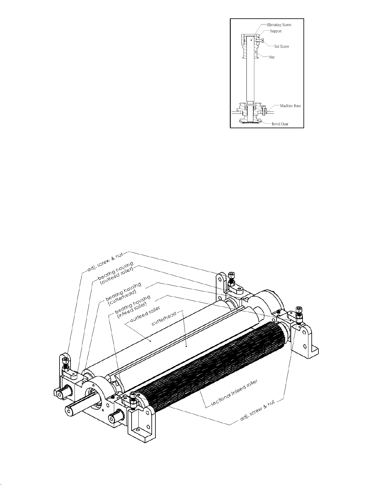
Recheck the right side and then lock the adj. screw with the nut
provided. The most accurate method of setting the infeed roll is
with the bed and feed roll gage. Find the low point of the knife arc
to the end of the gage then set the infeed roll to 0.062 for
sectionalized infeed rolls below the zero point. It is important that
the setting on both sides of this infeed roll be close to the same
height to help avoid skewing of the material as it is fed through the
machine. Infeed roll pressure is controlled by springs and is
adjusted by use of screws located under the side panels (Fig. 8)
pressure should be slightly higher on the drive side to help avoid
skewing of board as it feeds through.
Fig. 8
5-3 Chip Breaker:
The sectionalized chip breaker is constructed of 2"(50.8mm) wide spring-loaded sections mounted on a bar. Each sation has approximately
1/4"(6.4mm) independent yield. The functions of the chip breaker are to help avoid splintering out of the wood, to break chips into small
pieces, to help avoid board bounce thinner board bounce on thinner boards, to direct the flow of chip out of the machine. And to permit
multiple boards surfacing up to 1/4"(6.4mm) difference in thickness on the sectionalized type.
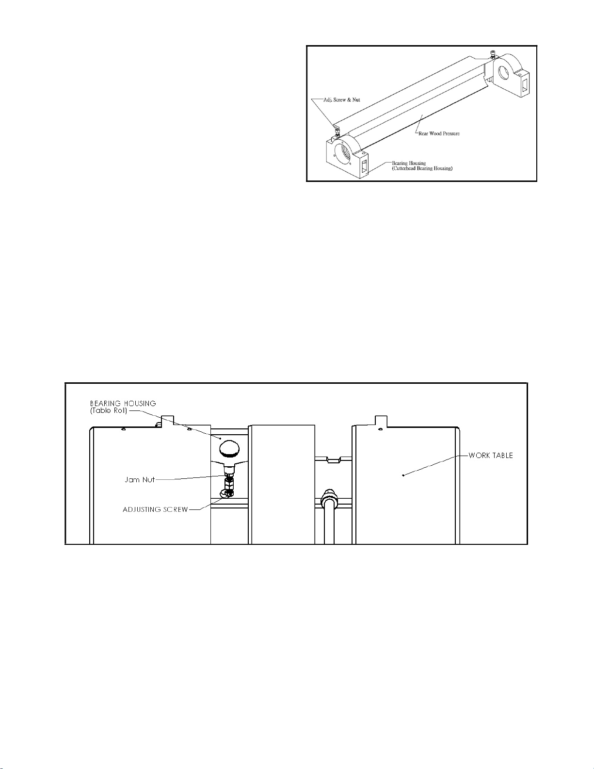
The chip breaker in its free position should 1/32" (0.8mm) below
the cutting arc of the knives, the same as the infeed roll, using the
same method as indicated for the infeed roll, remove the cover over
the top scction of the planer, adjust the chip brcaker free position
using a 2 x 4 gage block and shop scale of the proper thickness and
adjusting screws at each end. It is important that each end be close
to the same height to help avoid skewing of the material as it is fed
through the machine (Fig. 9)
(Caution: A chip breaker set too low may prevent stock from
feeding into the machine.)
Fig. 9
5-4 Outfeed Roll:
The outfeed roll is smooth and of one-piece construstion to help avoid marring the finished surface of the material being cut. Its function is to
continue to feed the material through the machine after it leaves the infeed roll. The correct free position setting is 1/32" (0.8mm) below the
arc of the cutterhead knives. Using the gage block or a finished 2 x 4 on edge with a 1/32" (0.8mm) shop scale on top under the cutterhead,
raise the table and rock the cutterhead to establish the low point of the knife arc. Remove the scale and position the gage or 2 x 4 under the
right side of the outfeed roll. Raise or lower its right hand bearing support with the adj. screws provided (Fig.8) to a light drag fit. Move the
gage or 2 x 4 under the left hand end and adjust in the same way. The most accurate method of setting the outfeed roll is with the bed and
feed roll gage. Zero the gage to the low point of the cutterhead arc and set each end of the outfeed roll to .031(0.787mm) below the zero on
both sides. Lock the adj. screws with the nuts provided. Out feed roll presure is controlled by springs and is adjsuted by use of screws located
under the side panels (Fig. 8). Unblanced pressure can result in skewing of the board as it feeds through.

8
5-5 Pressure Bar:
Most planing problems can be related to improper setting of the
pressure bar. Its functions are to hold the material down after it
passes under the cutterhead and throughout the remainder of the the
cut. Its basic setting is to be in line with the arc of cutterhead knives.
If it is too high, a shallow clip will occur in each end of the board.
If it is too low, stock will not feed through. (Fig. 10) With a bed and
feed roll gage or a gage block and a 1/32" (0.81mm) thick 6"
(152mm) scale as a feeler placed under the cutterhead, raise the
table with its elevating handwheel to determine the low point of the
arc of a cutterhead knife. Move the gage or gage block and scale
under the low point of the extreme right hand side of the table and
adjust that end of the pressure bar to be in line with the low point of
the knife arc. Move the gage of gage block and scale to the extreme
left hand side and adjust that side to be in line with the low point of
the knife arc. Using the bed and feed roll gage set the full length of
the pressure bar to be. 000-0.001(0.02mm) above the arc of the
cutterhead. This initial setup is a staring point and final adjustment
may have to be made during a test cut.
Fig. 10
5-6 Table rolls
Two table rolls are provided on the planer to help reduce the friction of the stock on the table as it feeds through the machine.
The required height of table rolls are according to that whether the bottom face of stock is flat or rough. The standard setting is 0.007" above
the table, if the gage shows the position is too height or too low. Lossen the jam nut just beneath the bearing hou.sing, and turn the adjusting
screw until the proper position then lock the jam nut (Fig. 7)
Fig. 7
5-7 Test cutting
Using a piece of semi-finished stock, set up for a 1/16" (1.58mm) deep cut with the quick-set adjustment at zero. Start the machine, and
standing to the left-hand side begin feeding the stock into the machine.
CAUTION: Never stand dircctly behind stock or allow anyone else to do so and do not bend down to see how the stock is feeding. Should a
kickback occur, a serious or fatal injury could result.
The infeed roll should take the material and force it under the chip breaker and cutterhead. If the material feeds through effortlessly, examine
the finished cut carefully for imperfections. Learning to read a board for imperfections will save hours in adjusting a planer to operate
properly. If "chip" marks occur in each end of the board, the pressure bar is too high. Turn both right and left hand adjusting screws the same
amount, and take another 1/16" (1.58mm) deep cut.

9
Re-examine the board. Continue the operat-adjust procedure until the clip marks disappear. Should the board fail to feed through, back off
slightly on both adjusting screws until feeding is smooth and the imperfections do not reappear. Lock the pressure bar adjusting screws with
the jam nuts provided.
CAUTION: Do not adjust pressure bar with cutterhead running.
Note: Adjustment of the pressure bar will be required whenever knives are resharpened and because wear which will occur on the cutting
edge of the knives, causing feed to be restricted. Feed restriction can also occur due to pitch buildup on the table. Be sure the table surface is
clean and dusting the surface with talc occasionally will aid in smoother feeding and help to prevent pitch buildup.
5-8 Knife Installation
Knife installation on planer can be a difficult and exacting process. If the knives are not to be jointed and ground, end to end and knife to
knife relationship must be held within 0.001" for accurate and smooth planing. To help avoid cutterhead distortion in changing out a set of
knives, remove and replace the knife in one slot before changing the next knife.
A. Clean all dust, chip, pitch and accumulated foreign matter from a cutterhead slot and off of its gib.
B. Working with one slot, drop knife spring in their holes located in each slot.
C. With the knife and gib against each other and the concave shaped surface of the gib up, insert into the slot. The back edge of the knife
bevel should be slightly below the outside diameter of the cutterhead. Lightly tighten the two outside and center gib screw. (Fig. 8)
Fig. 8
D. Take the cutterhead knife gage (Fig. 9) on the cutterhead outside diameter.

10
Fig. 9
E. Using an open-end wrench to slightly loosen knife gib adjsuting screws, raise the knife by spring to be approximately 2 mm projection
from the cutterhead body. Check the full length of the knife and be sure it is the same height.
F. Starting from the center outward, sung down all gib screws and then repeat process locking them.
G. Repeat the preceding method on successive knives making sure that the height from knife to knife is the same within 0.001".
H. After all knife have been installed, recheck all gib screws to be sure they are tight. Loose gib screws can result in knives being thrown
out of the cutterhead causing severe damage to the machine and possible serious or fatal injury to the operator or bystanders.
Note: If all knives have been removed, a new set must be installed without locking the gibs until all knives and gibs are in and the gib screws
lightly snugged down. The locking process should proceed working from the center out on each knife and after locking all gib screws once,
repeat the same sequence until all screws are equally tight. Locking one knife in without the other in position can cause cutterhead distortion.

11
PARTS LIST:
NO. PARTNO. DESCRIPTION Q"TY
1 T012029 Work Table Assembly 1
2 C003020 Left Base 1
3 C003002 Right Base 1
4 C007001 Gib 2
5 G002002 Elevator Bolt Assembly 1
6 S284008 Spring Washer,Φ10.2 4
7 S137030 Hex. Head Screw,M10-P1.5 4
8 C067064 Sprocket 1
9 C015017 Support, Handle 1
10 S282107 Washer,Φ6.4 3
11 S284006 Spring WasherΦ6.1 3
12 S201020 Hex. Socket Head Screw,M6-P1.0 3
13 S319201 Oil Fitting 1
14 S307086 40 Chain 1

12
PARTS LIST:
NO. PARTNO. DESCRIPTION Q"TY
1 C015094 Plate 1
2 T016008 Level Gear 1
3 S284007 Spring Washer,Φ8.2 10
4 S202025 Hex. Socket Head Screw,M8-P1.25 10
5 T003003 Level Screw 2

13
PARTS LIST:
NO. PARTNO. DESCRIPTION Q"TY
1 C009021 Support 1
2 P051001 Brass Bearing 1
3 S043004 Thrust Bearing 1
4 C035001 Shaft 1
5 C028001 Gear 1
6 S267512V Spring Pin 1
7 C037002 Collar 1

14
PARTS LIST:
NO. PARTNO. DESCRIPTION Q"TY
1 C015015 Support 2
2 P051001 Brass Bearing 2
3 C039026 Shaft 1
4 C028002 Bevel Gear 2
5 S267510V Spring Washer 3
6 C067018 Sprocket 1

15
PARTS LIST:
NO. PARTNO. DESCRIPTION Q"TY
1 C006054 Work Table 1
2 C015018 Support 1
3 S201016 Hex.Socket Head Screw,M6-P1.0 3
4 C017013 Elevator Arm 2
5 C046076 Rod 2
6 S267512V Spring Pin,Φ5 2
7 C051008 Bushing 2
8 S213015 Set Screw,M8-P1.25 2
9 C046010 Shaft 1
10 C049011 Short Plate 1
11 C049010 Long Plate 1
12 C051022 7L Bushing 4
13 S282108 Washer,Φ8.4 4
14 S284007 Spring Washer,Φ8.2 4
15 S202020 Hex. Socket Head Screw,M8-P1.25 4
16 C017014 Hub 1
17 C057006 Lever 1
18 S273012R Nut,M12-P1.75 1
19 P029214Y Hex.Socket Head Screw,M8-P1.25 1
20 S282110 Hub 1
21 P028001 Lever 1
22 S214030 Nut,M12-P1.75 6
23 S273010R Hex.Socket Head Screw,M8-P1.25 6

16

17
PARTS LIST:
NO. PARTNO. DESCRIPTION Q"TY
1 C002033 Base 1
2 S284008 Spring Washer,Φ10.2 24
3 S137040 Hex.Head Screw,M10-P1.5 3
4 S137030 Hex.Head Screw,M10-P1.5 9
5 S273010R Nut,M10-P1.5 12
6 T004051 Motor Assembly 1
7 S277006R Nut,M6-P1.0 2
8 C034031 Bolt, Motor 1
9 C051080 Collar, Handwheel 1
10 P025155G Handwheel 1
11 S213014 Fixed Screw,M8-P1.25 1
12 P028014N Knob 1
13 P031006 Star Knob 1
14 C078003 Boost, Bolt 2
15 C015022 Support, Bolt 2
16 S282108 Washer,Φ8.4 4
17 S284007 Spring Washer,Φ8.2 4
18 S136025 Hex. Head Screw,M8-P1.25 4
19 S136020 Hex. Head Screw,M8-P1.25 2

18
PARTS LIST:
NO. PARTNO. DESCRIPTION Q"TY
1 P041207L Motor,2P 7 1/2HP(5.5KW) .L 1
* P041208L Motor,2P 10HP(7.5KW) .L 1
2 C064140 Pulley 1
3 S214025 Fixed Screw,M10-P1.5 2
4 C063054 Support, Motor 1
5 S282011 Washer, Φ10.5 3
6 S284008 Spring Washer,∮10.2 6
7 S137045 Hex. Head Screw,M10-P1.5 3
8 S273042 Nut,M10-P1.5 3
9 C049001 Plate, Motor 1
10 C034030 Bolt 1
11 S282012 Washer,Φ13 2
12 S273043 Nut,M12-P1.75 4
Table of contents
Other Cantek Planer manuals
Popular Planer manuals by other brands

MasterCraft
MasterCraft 55-5504-2 Operation and safety instructions

Laguna Tools
Laguna Tools PX-20 SHEARTEC II owner's manual

MasterCraft
MasterCraft 54-6622-6 operating manual

Fox
Fox F22-561 Assembly and operating instructions

Makita
Makita KP312 instruction manual

EINHELL
EINHELL TC-SP 204 Original operating instructions