Cantek P630HV Application guide

Operations & Parts
Manual
www.cantekamerica.com
Please ensure you have your serial number available when contacting us for parts or service.
P630HV
SINGLE SURFACE PLANER

1
OPERATING INSTRUCTIONS
Before operating the unit, please read this manual thoroughly, and
retain it for future reference.
OWNER'S RECORD
The model and serial numbers of your set are located at the
front.Record the serial number in the space provided below. Refer
to these numbers whenever you call upon your dealer
regardingthis product.
MODEL NO._______________________
SERIAL NO._______________________
TABLE OF CONTENTS
Specifications ............................................................................................................................................................................................................. 2
Features Of Your 24"Planer .................................................................................................................................................................................. 3
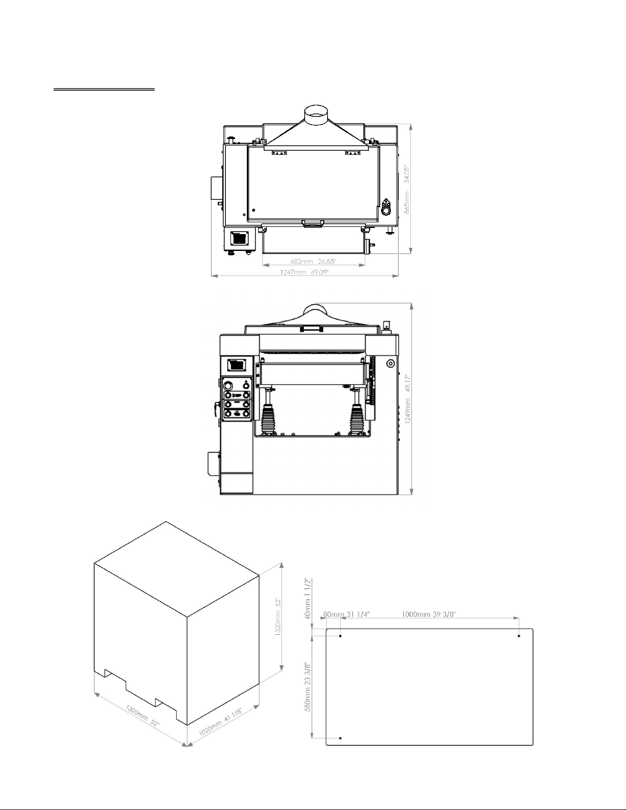
Dimensions ................................................................................................................................................................................................................. 4
General Safety Instructions .................................................................................................................................................................................. 5
Additional Safety Rules For Your Planer ......................................................................................................................................................... 6
Unpacking And Clean-UP ..................................................................................................................................................................................... 7
Installation Instructions ......................................................................................................................................................................................... 8
Installing ...................................................................................................................................................................................................................... 8
Grounding Information And Power Connections ....................................................................................................................................... 8
Adjustments And Operation ............................................................................................................................................................................... 9
Work Table .................................................................................................................................................................................................................. 9
Table Rollers ............................................................................................................................................................................................................ 10
The Depth Of Cut .................................................................................................................................................................................................. 10
Cutterhead ............................................................................................................................................................................................................... 11
Infeed Roller, Chipbreaker, Pressure Bar, Outfeed Roller and Tension Adjustment Of Infeed And Outfeed Rollers ... 12
Feed Speed Control ............................................................................................................................................................................................. 13
Feed Drive System ................................................................................................................................................................................................ 13
Maintenance .................................................................................................................................................................................................... 14-15
Trouble Shooting ........................................................................................................................................................................................... 16-17
Wiring Diagram............................................................................................................................................................................................... 18-19
Parts Lists ........................................................................................................................................................................................................... 20-52

2
SPECIFICATIONS
ELECTRICS:
Planer Motor ........................................................................................................................................................................... 10HP 3PH 30AMP
Feed Motor ................................................................................................................................................................................... 1HP 3PH 3AMP
Table Lift Motor ...................................................................................................................................................................1/2HP 3PH 1.5AMP
Total Required Amperage .................................................................................................................................................................... 34.5AMP
CAPACITY:
Max. Width Of Stock ......................................................................................................................................................... 630mm (24-13/16")
Max. Thickness Of Stock .................................................................................................................................................. 300mm (11-13/16")
Max. Depth Of Cut ........................................................................................................................................................................... 8mm (5/16")
Min. Length(uncutted) ....................................................................................................................................................... 220mm (8-11/16")
CUTTERHEAD:
Number Of Knives ............................................................................................................................................................................................ 4pcs
Diameter ..................................................................................................................................................................................... 98mm (3-27/32")
Cutting Circle ............................................................................................................................................................................ 102mm (4-1/64")
Speed ........................................................................................................................................................................................................ 5500R.P.M
TABLE SIZE:
Width....................................................................................................................................................................................... 685mm (26-31/32")
Length ....................................................................................................................................................................................... 870mm (34-5/16")
FEED ROLLERS:
Infeed (One Sectional) Dia. ............................................................................................................................................................... 76mm (3")
Outfeed (Two Solid) Dia. ........................................................................................................................................................... 60mm (2-3/8")
Table Roller (Two Smooth) Dia. ......................................................................................................................................... 68mm (2-11/16")
Feed Rate (Variable Speed) ............................................................................................................................................... 19 FPM to 39 FPM
MACHINE SIZE (LxWxH) .................................................................................... 1247mm x 865mm x 1249mm (49"x34"x49")
PACKING SIZE (LxWxH) ............................................................................ 1320mm x 1020mm x 1320mm(52"x41-1/8"x52")
NET WEIGHT ..................................................................................................................................................................... 820KGS (1804LBS)
GROSS WEIGHT .............................................................................................................................................................. 920KGS (2024LBS)
STANDARD EQUIPMENT
1. Two rollers, table with micro-metric adjustment. 8. Digital counter.
2. Variable feed speed system with 1HP motor. 9. Lifting table on four strong screws.
3. Power table, rise and fall with 1/2HP motor. 10. Magnetic switch.
4. Segmented infeed roller. 11. Dust extraction hood.
5. Sectional chipbreakers. 12. Adjusting tools & operations manual.
6. 4-Knife cutterhead. 13. Main motor: 10HP 3PH 220/440V 60cycle
7. Easy operation knife setting gage. 14. Cast iron frame.

3
FEATURES OF YOUR 24" PLANER
1. Dust Hood
2. Top Cover
3. Thickness Micro
Adjustment
4. Frame Cover
5. Right Side Cover
6. Power Indicator
Light
7. Emergency Stop Button
8. Digital Scale And
Control
9. Table Raising Button
10. Start Button, Planer
11. Start Feeding Button
12. Work Table
13. Control Panel
14. Limit Block, Width
15. Table Roller
16. Wiring Terminal Box
17. Table Roller
Adjustment Handle
18. Machine Base
19. Access Door
20. Variable Speed
Dial
21. Table Roller
Adjustment Lock
22. MM/INCH Scale

4
DIMENSIONS

5
Packing: outside measurement Base Dimension
GENERALSAFETY INSTRUCTIONS
1. Keep Guards In Place: Safety guards must be kept in place and in working order.
2. Remove Adjusting Keys And Wrenches:Before turning on machine, check to see that the keys, chucks and
adjusting wrenches are removed.
3. Reduce The Risk Of Unintentional Starting: Make sure switch is in the off position before plugging in the
machine.
4. Do Not Force Machines:They will do a job better and safer at the rate for which they were designed.
5. Use Right Tool: Do not force a machine or an attachment to do a job for which it was not designed.
6. Secure Work:Use clamps or a vise to hold work when practical. It's safer than using your hand and it frees both
hands to operate machines.
7. Maintain Machines With Care:Keep machines sharp and clean for the best and safest performance. Follow
instructions for lubricating and changing accessories.
8. Disconnect Machines From Power:Before servicing or when changing accessories such as bits, blades,
cutters, etc.disconnect from power.
9. Use Recommended Accessories:Consult the owner's manual for recommended accessories. The use of
improper accessories may cause risk of injuries.
10. Check Damaged Parts: Check for alignment of moving parts, binding of moving parts, breakage of parts,
mounting, and any other conditions that may affect the machine's operation. A guard or other part that is
damaged should be properly repaired or replaced.
11. Turn Power Off: NEVER LEAVE MACHINE RUNNING UNATTENDED. Do not leave machine until it comes to a
complete stop.
12. Keep Work Area Clean: Cluttered areas and benches invite accidents.
13. Do Not Use In Dangerous Environment: Do not use power machinesin damp or wet locations, or expose
them to rain. Keep work area well lighted.
14. Keep Children Away: All visitors should be kept at a safe distance from the work area.
15. Make Workshop Child Proof:Use padlocks, master switches, and remove starter keys.
16. Wear Proper Apparel: Loose clothing, gloves, neckties, rings, bracelets or other jewelry may get caught in
moving parts. Non-slip footwear is recommended. Wear protective hair covering to contain long hair.
17. Always Use Safety Glasses And Dust Masks: Use face or dust mask if cutting operation is dusty. Every day
eyeglasses only have impact resistant lenses, they ARE NOT safety at all times.

6
18. Never Stand On Machine: Serious injuries could occur if a moving part is unintentionally contacted.
ADDITIONAL SAFETY RULES FOR YOUR PLANER
1. This machine has been designed with as many safety features as humanly possible, however, always remember
that a planer is only as safe as its operator.
2. Before starting the planer, be sure to check the following:
A. Table must be completely free of all foreign matter.
B. Cutterhead knives MUST be inspected before each operation. Check for tightness in cutterhead and make
certain knives are not fractured in any place. Flying knives are DANGEROUS.
C. Check knives for sharpness.
3. Check material thickness and depth of cut desired. NEVER overload planer, or try to cut beyond its capacity.
4. As material is fed into machine, stand to side of board near switch (never directly behind)."Kick-back" is caused
by improper grip of lumber by infeed roll and chipbreaker, can cause serious injury.
5. NEVER stand directly behind or work behind machine when it is running. Direction of cutterhead rotation
usually throws chips or any foreign material from rear of machine.
6. In case it is necessary to stop material as it is through machine, switch off feed system and turn machine off.
WAIT until cutterhead has completely stopped before lowering table to remove material. Attempted removal
while cutterhead is turning may cause "Kick-back".
7. NEVER horse around a running planer. "Play"should absolutely be forbidden as 9 out of 10 accidents are the
results of carelessness and playing with machine as though it were atoy.
8. Always stop machine for adjustment of when leaving immediate area. Disconnect power source when working
on or around any moving parts.
9. CAUTION-Kickback can result and board flies from machine with high velocity. When sectional infeed rolls and
chipbreakers are installed, it is possible to feed several narrow boards through machine.
10. Use only factory authorized replacement parts and knives.
11. Keep all guards in place at all times.
12. Extra care should be taken when running short pieces, but with another piece of material of equal thickness and
stand ASIDE.
13. Do NOT tie strings to the table elevating screws or remove the protective rubber boots. The screws will be rusty
and plastic embeds on the screws. Failure to comply with the above warnings may cause personal injury and/or
damage to the machine.

7
UNPACKING AND CLEAN-UP
To ensure maximum performance from your planer, clean it properly, and install it accurately before use. As soon as
you receive the planer, we recommend you follow the procedures:
1. Inspect packing crate for damage in transit. Record damage and report it immediately to shipper.
2. Open crate and check that machine arrived in good condition. If not, let the distributor know immediately.
3. Before lifting machine, remove all bolts from its shipping base.
4. Transport machine to location with a hand truck or dolly.
5. ** IMPORTANT **
REMOVE THE PROTECTIVE COATING FROM THE TABLE, TABLE ROLLERS, FEED ROLLERS, CUTTERHEAD
AND LOOSE ITEMS PACKED WITH THE MACHINE.
6. The coating may be removed with a soft cloth moistened with Kerosene.
NOTE: DO NOT USE ACETONE, GASOLINE, OR LACQUER THINNER FOR THIS PURPOSE
7. DO NOT use solvents on plastic parts; they will dissolve plastic.
8. ** CAUTION **
CARE MUST BE TAKEN WHEN CLEANING THE CUTTERHEAD. The knives are in the cutterhead and are very
sharp.
9. For lifting, please refer to Fig. 1
Fig. 1

8
INSTALLATION INSTRUCTIONS
IMPORTANT(PALESE READ CAREFULLY)
Installing
Mount machine securely to solid, even base foundation. Concrete base mounting preferred. Locate in clean, dry, well
lighted and well ventilated building if possible. With machine in position, test table surface lengthwise and crosswise
with machinist level. Place metal shims under low corners. Check that all four corners are supported.
Grounding Information And Power Connections
1. ** IMPORTANT **
Before connecting to the power source, be sure that the voltage is the same characteristics as tied on terminal
box.
RUNNING ON WRONG VOLTAGE WILL INJURY THE MOTOR
2. The necessary wiring to the power source should be completed by a competent electrician.
For personal safety, this machine must be properly grounded. Base of machine should be grounded to central
grounding system.
3. NOTE: After wiring into the power source, run motor without load to check the direction of rotation.
4. Please refer to Fig. 2, Fig. 3 of Control Panel and Connections To Power source.
CONTROL PANEL
Fig. 2 Fig. 3
CONNECTION TO POWER SOURCE NOTE: SELECT WIRE SIZE TO MEET TOOL
REQUIRED AMPERAGE OF
34.5AMP/220V
17.25AMP/440V

9
ADJUSTMENTS AND OPERATION
Disconnect machine from the power source before adjusting this machine.
OPERATING ADJUSTMENTS.
WARNING: Before checking adjustments, always make sure the planer is disconnected form the power source.
Work Table
The work table is mounted on the frame and is raised or lowered on four screws mounted on thrust bearings. The
work table is raised or lowered by 1/2HP motor power control or micro adjustment. The work table MUST BE parallel
to the cutterhead. This can be checked by lowering the work table to permit placing a small square block between
the work table and the cutterheadat the extreme right side of the table. Raise the table with the handle until the block
just touch the cutterhead and move the block to the left side of the table and check the cutterhead. If the table is not
parallel to the cutterhead, perform the adjustment procedures as follow:
1. Disconnect the machine from the power source.
2. Remove the boot (C) for access to screw,
3. Loosen lock bar (A) and turn acme screw (B) in clockwise direction, then adjust it to accurate position as shown
in Fig. 4.
Limitation for work table raising or lowering, there is a limit switch (A) for each direction of table movement. The
power table switches off to prevent damage in maximum high and low position as shown in Fig. 5 (B) is a limit block,
micro-switch block.
(A) Limit switch
(B) Limit switch stop
NOTE: The most accurate way to check cutter alignment with table parallel is with the use of a dial indicator
mounted on a surface gage.
Fig. 4
A. Lock Bar
B. Rubber Dust Boot
C. Acme Screw

10
Disconnect machine from the power source before adjusting this machine.
Table Rollers
The table rollers are adjusted to the proper height with the quick-set handle mounted on the right side of the work
table. As a general rule, when planning rough stock, the table rollers should be set at high position, and when
planning smooth stock, the table rollers should be set at low position.
NOTE: The table rollers must always be set parallel to the work table.
1. Quick adjustment for planning rough stock and smooth stock:
A. Loosen lock handle (A) and move adjusting handle (B) up to the expected position as shown in Fig. 6
B. Lock handle (A).
2. Table rollers can be adjusted depending on working situation. However, the Max adjustment height is .125"as
shown in Fig. 7.
The Depth of Cut
This planer is equipped with easy-to-read digital thickness display and a thickness scale. Cutting thickness is up to
11-13/16". Power table up and down travel makes it easy to select desired material thickness.
When power table reaches the approximate material size, using the micro adjustment adjust (A) for manual
positioning. The digital display displays increments of .001" see Fig. 8
Fig. 6
A. Lock Handle
B. Adjusting Handle
Fig. 7
Fig. 8
A. Manual Micro Adjustment
B. Thickness Scale
C. Digital Display

11
Cutterhead
The cutterhead is equipped with four knives. It is important that knives should be kept sharp. The knives do all of the
work and they will not work if they are DULL. The set of knives are matched and balanced at the factory. When the
knives are sharpened, care should be taken that they are kept in balance. If the knives are removed for sharpening,
care must be exercised in replacing and resetting them, proceed as follows:
**CAUTION**
1. Disconnect the machine from the power source.
2. Clean the cutterhead
3. To remove knives, loosen the knife gib (D), by turning the square head screw (E) into the knife gib (D) then
remove the knife gib (D), knife (C) and two lifting springs (F) which located under the knife. Please take note that
the springs may pop out while removing the knife. Fig. 10
4. Remove the remaining three knives in the same manner.
5. Thoroughly clean the knife slots, knife gibs, springs and square head locking screws. Check the screws if they
appear worn or if the heads are becoming rounded, replace them.
6. In sequence to insert springs, knife, and knife gib into slot of the cutterhead. Backing out square head screws
just enough to hold the knife in the cutterhead.
7. Place the knife setting gage (B) over the knife. Loosen all square head screws by turning them into the knife gib
until cutting edge of knife comes into contact with the protrusion of gage. Then lightly back out the square
screws against the slot.
**NOTE:AT THIS TIME, ONLY TIGHTEN THE SCREWS JUST ENOUGH TO HOLD THE KNIFE IN POSITION.
8. Replace and reset the other three knives in the same manner.
9. After all four knives are set in position, back out and tighten the square head screws against the slot starting
with the end screws first and the center screws until the knife is securely held in the cutterhead. Tighten the
remaining three knives in the same manner.
**NOTE: Double check all screws for tightness
Fig. 9
Always Feed Against the Cutter Rotation As Shown
In Fig. 9
Fig. 10
A. Knob D. Knife Gib
B. Knife setting gage E. Square head screw
C. Knife F. Lifting spring

12
Infeed Roller, Chipbreaker, Pressure Bar, AndOutfeed Roller
The infeed roller, chipbreaker, pressure bar, and outfeed rollers are adjusted at the factory. The infeed roller and the
chipbreaker are to be set .020"below the cutting circle, the pressure bar is to be set .040" below the cutting circle and
the outfeed rollers are to be set .020" below the cutting circle, as shown in Fig.11 For example to check and adjust
the outfeed roller below the cutting circle .020", proceed as follows:
1. Disconnect machine from the power source.
2. Make sure the knives are adjusted properly.
3. Place a square block on the table directly underneath the cutterhead. Place a feeler gage on top of the square
block. Raise the work table until the knife tip just touches the feeler gage. Do not move the work table any more
until theoutfeed roller is adjusted as shown in Fig. 12.
4. If an adjustment to the outfeed roller is necessary, loosen the lock nut (A) and turn screws (B) until the outfeed
roller just touches the square block. Then tighten lock nut (A) as shown in Fig. 13.
5. Check and adjust opposite end of the outfeed roller in the same manner.
Tension Adjustment OfInfeed And Outfeed Rollers
Adjust the spring tension of the infeed and outfeed rollers by turning the spring tension adjustment screw (F) as
shown in Fig. 13.
A. Lock nut
B. Adjustment screw
C. Roller
D. Bushing housing
E. Spring
F. Spring tension screw
Fig. 12
Fig. 13

13
Feed Speed Control
This planer is equipped with a separate 1HP feed motor and variable feed speed control system. The feed rates are
from 19 FPM to 39 FPM which meets the different requirement of soft stock and hard stock. It is easy to adjust by
turning the dial knob (A) as shown in Fig.14. The variable speed adjustment dial (A) turns clockwise for low speed
feeding and counterclockwise for higher speed selection.
Feed Drive System
1. Chain Drive
Feeding transmission instruction:
Please adjust (C) when drive chain become loose, as shown in Fig. 15.
2. V-Belt Drive
Adjust (A) to have a proper position when belt becomes loose by lowering motor frame.
A. Drive pulley variable drive
B. Drive pulley variable drive
C. Chain tension idler.
Fig. 14
Fig. 15

14
MAINTENANCE
BEFORE STARTING MAINTENANCE OR LUBRICATION, PLEASE DISCONNECT MACHINE FROM THE
POWER SOURCE.
1. Daily Maintenance:
Make sure all nuts and bolts are tight and retainer springs are secured. Keep knives sharp. Observe all safety
precautions. Care should be taken to prevent dust from embedding on moving parts in the machine.
It is worth to do regular and careful cleaning of machines that can forestall many of the common drawbacks
that arise during running, as well as helping cut maintenance costs.
Clean the machine after the end of shift.
2. Lubrication:
Lubricate the lub points as shown in Fig. 16
Lubrication Guide Of Your Planer
Index Position Interval Type Of Oil
A.
B.
C.
Feed Roller Bushings
Table Life Screws(4)
Table Side Ways(4)
Oil Daily
Frequently
Frequently
SAE-30
Grease
SAR-30
Fig. 16

15
3. Belt Tension:
Maintain proper belt tension to cutter rotor. New belts must be checked the first 3 days of operation until they are
seated.
Increase belt tension as shown in Fig. 17 by lowering the adjustment bracket.
A. Motor support bar
B. Mounting bracket
C. Tension adjustment screw
D. Adjustment bracket
Fig. 17

16
TROUBLE SHOOTING
Symptom Possible Causes And Check
1. If clip or snip appears at beginning of stock. Pressure bar may be set too low.
Chipbreakermay be set too high.
Upper infeed sectional roller may be set too high.
Table infeed roller may be set too high.
Spring tension may be too light on pressure bar.
Table rollers may be too high.
2. If clip or snip appears on end of stock. Pressure bar may be set too high.
Table outfeed roller may be set too high.
Upper outfeed roller may be set too low.
Stock may not be butted.
Grain may be running against knives.
Table rollers may be too high.
3. If knives tear out stock. Feed may be too fast.
Moisture content may be too high.
Cut may be too heavy.
Cutting angle may be too large.
Grain may be running against knives.
Knives are dull.
4. If knives raise the grain. Feed may be too fast.
Cutting angle may be too large.
Moisture content of stock may be too high.
Cut may be too heavy.
Knives need sharpening.
5. If chip marks appear on stock. Blower system may not be strong enough. No
suction.
Feed may be too fast.
Exhaust pipe may connect with too large on angle
to main blower pipe.
Check knife edge.
6. If panels are taper across the width Planer bed out of parallel with cutterhead.
Knives not set even in cutterhead.
7. If undesired glossy finish appears. Knives may be dull.
Feed may be too slow.

17
TROUBLE SHOOTING
Symptom Possible Causes And Check
8. If washboard finish appears. Knives may have been driven back into the head.
Machine may be completely out of adjustment.
Planer bed loose and rocking in ways.
9. If revolution mark shows up. Knives may be ground poorly.
Knives not set properly or evenly.
10. If lines appear at right angles to the knife marks. Knives may have nicked by overgrinding and
taking temper out of steel.
Chips may have wedged between rolls and tables.
Pressure bar may be dragging
11. If stock twists in machine. Pressure bar may be cocked.
Upper outfeed roller may be cocked.
Upper outfeed roller may have uneven spring
tension.
Table rollers may be cocked.
12. If machine is noisy, vibrate and pounds. Knives may be too dull.
Machine may not be leveled correctly.
Machine may not be on solid foundation.
Pressure bar may be set too low.
13. If stock sticks or hesitates in machine Pressure bar may be set too low.
Table rollers may be set too low.
Feed rollers may not be set low enough.
Cut may be too heavy.
A push board may help stock through machine.
Check moisture content
14. If motor kicks out Knives may be dull, thus overloading motors
Pressure bar may be set too low, putting drag on
motors.
Motors may be drawing high current because
other machinery in the plant in use has pulled
down the voltage.
Machine may be out of adjustment.
Table rollers may be set too low.
Too heavy cuts with continued work load.

18
Wiring
Diagram
A. 10Hp Magnetic switch
B. 1Hp Magnetic switch
C. 1/2 Reversible switch
D. 1/2 Reversible switch
E. Transformer
F. Fuse
G. Terminal
H. Power Lamp ∮30
I. Run Lamp ∮30
J. Emergency stop bottom ∮30
K. Sensor X2 PL-05NB-S
L. Green Bottom ∮30
M. Red Bottom ∮30
N. Yellow Bottom ∮30
O. Yellow Bottom ∮30
P. Green Bottom ∮30
Q. Red Bottom ∮30
R. Limited switch TZ-7311
S. Limited switch TZ-7311
T. Timer TRD-N

19
Table of contents
Other Cantek Planer manuals