CANTO USA Astro 250 User manual

V 1.0 4/19/22 1
Innovative Lighting Products
1092 West Atlanta Street, SE • Suite 600 • Marietta, GA 30060 • 888-252-5912 • [email protected] • cantousa.com
CANTO®FOLLOWSPOT
OPERATING INSTRUCTIONS
FOR THE NORTH AMERICAN REGION 120/208V 60 HZ
MODELS COVERED
01207080 Canto®Astro 250
A01607170 Canto®Astro 600
We hope that this product will meet your requirements, but if for any reason this should not be the case, we ask that you
contact us directly at 888-252-5912 to help address your needs. We wish to provide all of our customers with the best
quality products available. The product you purchased has been manufactured with maximum care in construction and
choice of components. If you have received your equipment damaged for any reason beyond our control, please contact
your local dealer who supplied the product to you within 72 hours after receiving our product.

Innovative Lighting Products
Followspot Operating Instructions
V 1.0 4/19/22 2
1092 West Atlanta Street, SE • Suite 600 • Marietta, GA 30060 • 888-252-5912 • [email protected] • cantousa.com
TABLE OF CONTENTS
01. Important Safety Notes ............................................................................... page 3
02. Check box contents ..................................................................................... page 4
03. Mounting the spigot .................................................................................... page 4
04. Mounting the color changer ......................................................................... page 5
05. Mounting the iris diaphragm ........................................................................ page 5
06. Shutter blades ............................................................................................ page 5
07. Adjusting the yoke ...................................................................................... page 5
08. Wiring ...................................................................................................... page 6
09. Voltage ..................................................................................................... page 6
10. Local Control Panel and Operation .............................................................. page 6
11. Menu ........................................................................................................ page 7
11.1 DMX or manual mode ........................................................................... page 7
11.2 DMX address ........................................................................................ page 7
11.3 Dimmer Resolution ................................................................................. page 8
11.4 Lost DMX Signal .................................................................................... page 8
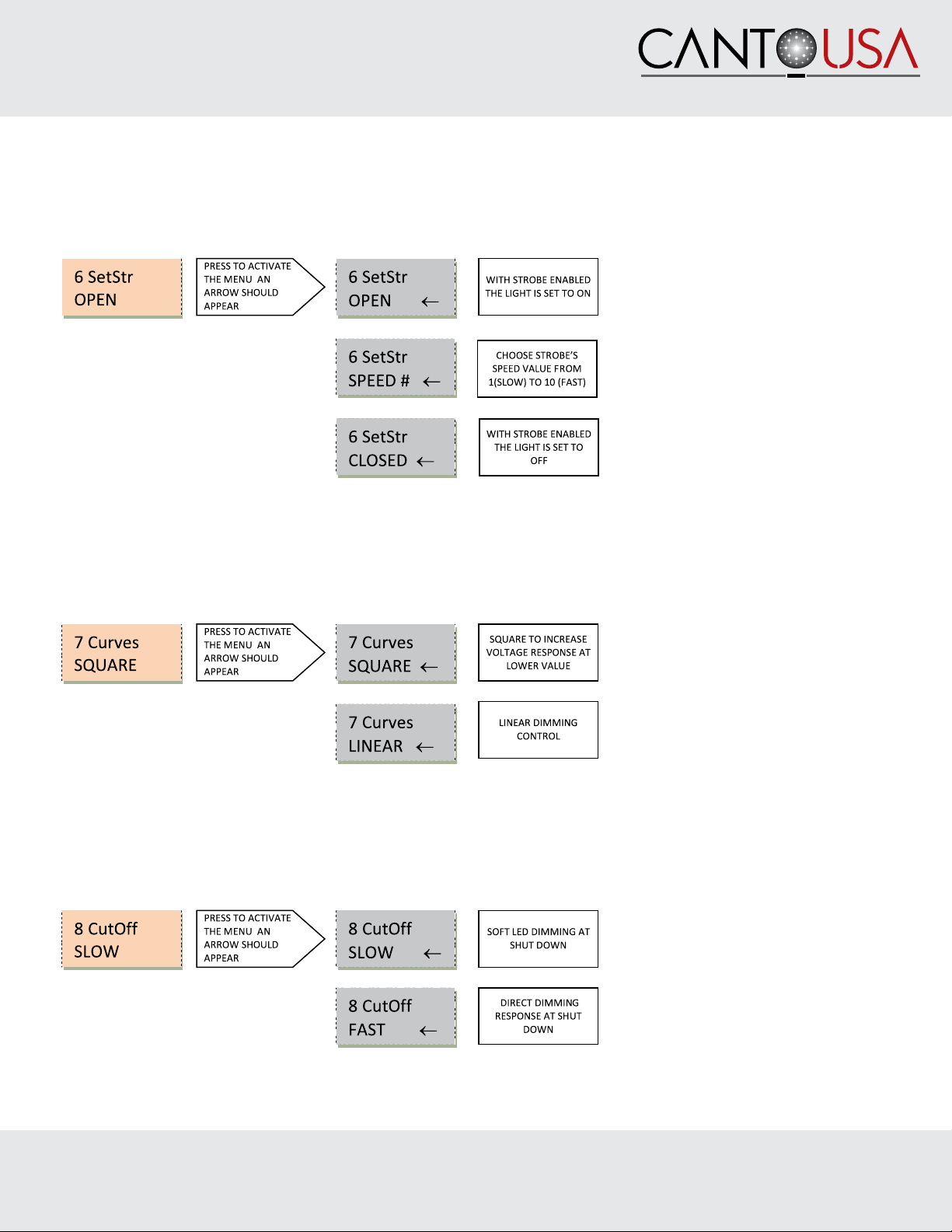
11.5 Strobe ................................................................................................. page 8
11.6 Strobe Speed......................................................................................... page 9
11.7 Dimming curve ..................................................................................... page 9
11.8 Cut off dimming response ....................................................................... page 9
11.9 Dimming behavior ................................................................................. page 10
11.10 Fan Setting ......................................................................................... page 10
11.11 LCD Screen Illumination ....................................................................... page 11
11.12 Temperature control ............................................................................. page 11
11.13 Software version ................................................................................. page 11
11.14 Manual dimmer Type ........................................................................... page 11
11.15 Pro or basic control ............................................................................. page 12
11.16 Factory setting .................................................................................... page 12
11.17 ID REMOTO ....................................................................................... page 12
11.18 Calibration ......................................................................................... page 13
11.19 Exit Hidden menu ................................................................................ page 13
12. Clamp-on mobile digital dimmer .................................................................. page 13
13. Focusing ................................................................................................... page 13
14. Cleaning and maintenance ......................................................................... page 14
15. Spare sparts .............................................................................................. page 14
16. Warranty .................................................................................................. page 14
17. Available accessories ................................................................................. page 15
18. Summary of controls and functions ............................................................... page 16
19. DMX charts ............................................................................................... page 18
19.1 DMX CHART 1 (16 bit dimmer and strobe disabled) .................................. page 18
19.2 DMX CHART 2 (16 bit dimmer inabled, strobe disabled) ........................... page 18
19.3 DMX CHART 3 (strobe functions inabled, 8 bit dimmer) ............................. page 19
19.4 DIMX CHART 4 (16 bit dimmer and strobe inabled) .................................. page 20

Innovative Lighting Products
Followspot Operating Instructions
V 1.0 4/19/22 3
1092 West Atlanta Street, SE • Suite 600 • Marietta, GA 30060 • 888-252-5912 • [email protected] • cantousa.com
CAREFULLY READ THE OPERATING INSTRUCTIONS BEFORE USING THIS FIXTURE.
The instructions given here ensure safe usage of this product. User’s failure to comply with the installation, operation,
maintenance and safety procedures mentioned in this manual as well as those generally applicable to lighting equipment,
may cause the fixture not to perform as expected.
CantoUSA accepts no liability for direct, indirect, incidental, special, or consequential damages resulting from the customer’s
failure to follow the installation, operating, maintenance and safety procedures described in this manual. These limitations
extend to damages for personal injury, property damage, loss of operation, loss of profits, loss of product or loss of time,
whether incurred by the customer, the customer’s employees, or third-party vendors or users.
Apart from the instructions given in this manual, all relevant safety and health standards of the appropriate local city and
state electrical / safety directives must be complied with.
PLEASE SEE OUR GENERAL TERMS OF SALE AND WARRANTY CARD PROVIDED WITH YOUR NEW EQUIPMENT OR
EMAIL US FOR A COPY AT ANY TIME.
1. IMPORTANT SAFETY NOTES
This product may reach high temperatures depending on the model ordered. Avoid any direct contact with its metal exhaust parts.
*NEVER WORK INSIDE AN OPERATING UNIT WITHOUT IT BEING COOLED AND UNPLUGGED FROM
POWER SOURCE. NEVER EVER WORK INSIDE A UNIT THAT IS TURNED ON.
*WARNING: HIGH VOLTAGE IGNITION, DISCONNECT THE UNIT FROM POWER BEFORE SERVICING
* Continuous mains power is required for this spotlight as an internal dimmer controls the intensity via DMX or local rotary
knob. An accessory moving manual dimmer is furthermore available for positioning on the side grab handles.
* Use of a phase control dimmed mains supply may damage the internal electronics.
* This product features fan-assisted ventilation. Make sure you do not cover the fans or obstruct the air flow at any one time.
* Make sure the fans are working correctly. Should you detect even the slightest malfunction, switch the luminaire off and
carry out the necessary servicing. Replace the fans if necessary.
* This product is rated IP 20 and is therefore designed for interior use only. For details on maximum ambient temperature,
minimum distance from flammable objects and tilt angle, please refer to what indicated on the product label.
* Repairing and replacement of any component of this product must be carried out exclusively by professional personnel in
conformity with the relevant safety and health standards and only with original Canto USA components.
* Replacement of any part of the wiring system must be carried out exclusively by professional personnel in compliance with
the original wiring diagram and with components identical to or compatible with those originally fitted.
* Installation of this product must be exclusively carried out by professional personnel

Innovative Lighting Products
Followspot Operating Instructions
V 1.0 4/19/22 4
1092 West Atlanta Street, SE • Suite 600 • Marietta, GA 30060 • 888-252-5912 • [email protected] • cantousa.com
BEFORE YOU GET STARTED, PLEASE READ THIS INSTRUCTION MANUAL
COMPLETELY.
2. CHECKING BOX CONTENTS:
Upon opening the boxes, please make sure the boxes contain the following items:
FOLLOWSPOT:
A. In case you bought just the followspot
1. Fixture:
a. Followspot in the chosen model
b. Separate mains power cable with PowerCon
c. Iris diaphragm
d. 28mm spigot with M12 self locking nut and plain washer
e. Clamp-on digital dimmer A20702071
B. In case you bought the complete kit
a. Followspot in the chosen model
b. Separate mains power cable with PowerCon
c. Iris diaphragm
d. 28mm spigot with M12 self locking nut and plain washer
e. Clamp-on digital dimmer A20702071
TRIPOD STAND:
Tripod – May or may not include casters for the tripod. Casters are an accessory that can be purchased.
3. MOUNTING THE SPIGOT:
Make sure the tripod you are going to use features a (28mm) top aperture for the supplied spigot.
Remove the M12 nut and washer from the spigot and insert the threaded end into the center hole of the yoke of the
followspot from beneath the yoke. Tighten the M12 nut with a suitable tool so that the spigot securely holds the followspot in
place but allows proper movement of the fixture.
Loosen the “T” Handle screw where the spigot inserts into the tripod. Mount the followspot onto the tripod. Place the tripod
in such a manner where the “T” Handle screw runs parallel to the yoke. Make sure the spigot shaft sits 12mm above the
base of the tripod. There is a recess in the spigot shaft just below the base that is a good indication of where to mount the
spigot. Make sure the area you are placing the product on can withstand the product load (see product label to check on
weight) i.e. catwalk or balcony.

Innovative Lighting Products
Followspot Operating Instructions
V 1.0 4/19/22 5
1092 West Atlanta Street, SE • Suite 600 • Marietta, GA 30060 • 888-252-5912 • [email protected] • cantousa.com
4. MOUNTING THE COLOR CHANGER:
1. At the front of the followspot, lossen the 2 phillips screws from one of the two front color runners.
2. Repeat with the second color runner.
3. Mount color filters on the color changer units. See relevant instructions supplied with the color changer.
4. Position the color changer unit on the front plate of the followspot, making sure that the color levers are positioned
on the right-hand side of the followspot when viewed from behind and hang it to the previously positioned screws.
5. Release the color filters of the color changer in order to have access to the screws and tighten them.
6. Ensure the color changer unit is secure, and all three screws are tight.
5. MOUNTING THE IRIS DIAPHRAGM:
The iris diaphragm supplied with the followspot has 20 leaves to size the beam from a maximum aperture of 68mm to a
minimum of 5mm. A black-out iris diaphragm is available to special order.
1. Using a Phillips screw-driver remove the two phillips screws from the sides of the iris plate.
2. Slide the diaphragm in the gate area.
3. Tighten the screws.
IMPORTANT NOTICE: DO NOT LEAVE THE IRIS CLOSED FOR OVER 5 MINUTES WHILE THE LED IS ON
FAILURE TO COMPLY WITH THE ABOVE NOTICE MAY CAUSE THE IRIS AND THE FOLLOWSPOT TO SUFFER
MAJOR HEAT DAMAGE AND WILL INVALIDATE THE PRODUCT WARRANTY.
6. SHUTTER BLADES:
Shutter blades are not supplied with the unit, but are available as a separate accessory. They are sold as single items and
the relevant part number is R80208019. 4 are required.
7. ADJUSTING THE YOKE:
This followspot is provided with a yoke balancing adjustment. The balancing point is factory set for a standard usage of
the product configuration supplied (without color); however, should you need to adjust the balancing, please proceed as
follows:
1. The followspot must be mounted on the tripod stand with all relevant accessories attached.
2. Using a Phillips screw-driver, loosen the 2 (M5) screws on each side of the mounting plate of the yoke.
3. Gently slide the followspot backward or forward to the required position.
4. Make sure the yoke is correctly aligned horizontally.
5. Tighten the 4 5mm screws.

Innovative Lighting Products
Followspot Operating Instructions
V 1.0 4/19/22 6
1092 West Atlanta Street, SE • Suite 600 • Marietta, GA 30060 • 888-252-5912 • [email protected] • cantousa.com
8. WIRING:
Before being connected to power, please make sure that the unit is outfitted with a suitable plug. Make sure the plug conforms
to the lamp power load. This fixture must be grounded. Ensure the plug conforms to the relevant local safety requirement and
UL electrical standards.
To perform a correct wiring, please note that the cores in this mains lead are color-coded as follows:
Ground: green+yellow – Neutral: blue - Hot: brown
In case the colors of the wires do not correspond to the color of the connection points on your plug, please proceed as follows:
• The green or green and yellow wire is ground and must be connected to the connection point marked with the
letter E or with the symbol or colored in green or in green+yellow
• The blue wire is neutral and must be connected to the connection point marked with the letter N or with the
symbol or colored in black
• The brown wire is hot and must be connected to the connection point marked with the letter L or with the
symbol or colored in red
Before you finally position this product for use, temporarily connect it to a properly fused power supply to check the lamp
works correctly.
9. VOLTAGE:
Before operating this unit please refer to the product label mounted at the back of the luminaire to
check you are operating with the correct voltage.
The Astro 250 LED and 600 LED can be operated between 120V and 208 V.
10. LOCAL CONTROL PANEL AND OPERATION:
OPERATION: LCD display for DMX address, system setup and status details.
POWER: power LED status indicator , red color. ON= power
DMX: DMX LED status indicator, green color. LED OFF = DMX OFF and manual control activated ,
LED ON = DMX MODE activated with no DMX signal, FLASHING LED = receiving DMX
MENU: rotary switch selector to select and modify the operational modes.
Turn left or right to navigate through the menu and press to select or to confirm
DMX IN: input DMX signal (pin1=0 , pin2= DATA- , pin3=DATA+ ).
DMX OUT : Loop through DMX signal output
POWER IN: Mains power input
POWER OUT: Mains power output

Innovative Lighting Products
Followspot Operating Instructions
V 1.0 4/19/22 7
1092 West Atlanta Street, SE • Suite 600 • Marietta, GA 30060 • 888-252-5912 • [email protected] • cantousa.com
11 MENU:
There are fourteen different menus to control the settings of ASTRO LED. The rotary selector is used to adjust the settings
and to navigate through the menu. Turn left or right to select the menu and push to access or to confirm the selected data or
functions. To exit the selected menus without saving the data, press the rotary selector for at least 1 second.
11.1 DMX OR MANUAL (MODE):
Select the LED control mode between OMX (factory setting) and manual. To change the control mode press once the rotary
selector until an arrow (0) appears on the menu. Turn the selector to the right or the left to select the desired mode of
operation and press to confirm your selection.
Tap the rotary selector and the LCD screen will display the mode status and the current value:
11.2 DMX ADDRESS (ADDR):
It allows to select the initial DMX starting address to remotely control the LED functions. To change the initial DMX address
press the rotary switch until an arrow appears, then turn to change to the desired DMX starting address. Press to confirm
your selection. Factory setting is 001.

Innovative Lighting Products
Followspot Operating Instructions
V 1.0 4/19/22 8
1092 West Atlanta Street, SE • Suite 600 • Marietta, GA 30060 • 888-252-5912 • [email protected] • cantousa.com
11.3 DIMMER RESOLUTION (8/16B):
The dimming resolution can be controlled at 8 bits from one DMX channel to 16 bits with 2 DMX channels. Factory setting is
8 Bit.
11.4 LOST DMX SIGNAL (DMXMEM):
In case of signal failure this function allows to store in memory the last DMX value. Factory setting is ON. Three options are
available:
11.5 STROBE (STROBE):
This function allows to activate the strobe function. Factory setting is DISABLE.

Innovative Lighting Products
Followspot Operating Instructions
V 1.0 4/19/22 9
1092 West Atlanta Street, SE • Suite 600 • Marietta, GA 30060 • 888-252-5912 • [email protected] • cantousa.com
11.6 STROBE SPEED (SETSTR):
It allows to set the strobe speed. This menu is not active when the strobe function is disabled or when it is remotely controlled
through DMX. Factory setting is OPEN.
11.7 DIMMING CURVE (CURVES):
This function allows to select a response curve for the Astro. A choice of two curves is available: Square and Linear.
Factoring setting is SQUARE.
11.8 CUT OFF DIMMING RESPONSE (CUTOFF):
This function allows to select a LED behavior simulating a tungsten-halogen lamp during the dimming cut off. Factory setting
is SLOW.

Innovative Lighting Products
Followspot Operating Instructions
V 1.0 4/19/22 10
1092 West Atlanta Street, SE • Suite 600 • Marietta, GA 30060 • 888-252-5912 • [email protected] • cantousa.com
11.9 DIMMING BEHAVIOR (SMOOTH):
This function allows to set the LED dimming response. Factory setting is NORMAL.
11.10 FAN SETTING (FAN):
This function allows to set the fan’s response. A choice of three modes is available: Automatic, Silent or Steady. When
fan is in Auto mode, the speed is controlled by the LED temperature. In Silent mode the fan runs slowly to reduce noise. In
Steady mode the fan runs at constant speed, halfway between the minimum and maximum speed. In all cases, if the LED
temperature exceeds the maximum admitted value, the LED is protected by a de-rating security system. Factory setting is
AUTO.

Innovative Lighting Products
Followspot Operating Instructions
V 1.0 4/19/22 11
1092 West Atlanta Street, SE • Suite 600 • Marietta, GA 30060 • 888-252-5912 • [email protected] • cantousa.com
11.11 LCD SCREEN ILLUMINATION (BACKL):
This function allows to turn off the LCD backlight, the POWER led and the DMX led light after 1’30” from the last setting.
Factory setting is AutoOFF.
11.12 TEMPERATURE CONTROL (TLED):
This function allows to visualize the LED temperature. Factory setting is °C.
12 12 12
11.13 SOFTWARE VERSION (SWVER):
This function allows to visualize the software version.
11.14 MANUAL DIMMER TYPE (MANU):
This function allows to select the manual dimmer type. An additional movable manual dimmer, which can be clamped-on In
any po sition of each of the side control handles, is available as an additional accessory as follows:
A20702071 ASTRO SIDE-HANDLE CLAMP-ON MANUAL DIMMER
Factory setting is ENCODER

Innovative Lighting Products
Followspot Operating Instructions
V 1.0 4/19/22 12
1092 West Atlanta Street, SE • Suite 600 • Marietta, GA 30060 • 888-252-5912 • [email protected] • cantousa.com
HIDDEN MENUS
There are also four different hidden menus to select the advanced settings of the ASTRO LED. To activate this function turn
OFF and ON the Astra by pressing the rotary switch at power on.
11.15 PRO OR BASIC CONTROL (PROBASIC):
The PRO-BASIC control is a special function which allows to limit the access to the control menu. Select ProBasic with the
rotary switch and press to access the menu. Select: PRO, to enable access to all the functions BASIC, to limit access to
functions 5.1 DMX or MANUAL MODE, 5.2 OMX ADDRESS, 5.12 Temperature Control and S,13 Software version. Factory
setting is PRO.
11.16 FACTORY SETTINGS (RESET):
The RESET control is a special function which allows to RESET the product to factory settings.
11.17 ID REMOTO (ID REM):
Remoto Is a control device which allows to upgrade your Astro with the latest software version or to load and download
stored info. It Is available as an optional accessory as follows:
A20702072 REMOTO control unit
To change the initial ID press the rotary switch until an arrow appears, then turn to change to the desired ID number. Press
to confirm your selection. It is possible to select an ID number from Oto 250. If ID number=0 remote control is not active.
Factory setting is 000.

Innovative Lighting Products
Followspot Operating Instructions
V 1.0 4/19/22 13
1092 West Atlanta Street, SE • Suite 600 • Marietta, GA 30060 • 888-252-5912 • [email protected] • cantousa.com
11.18 CALIBRATION (SET MIN):
It allows to calibrate the minimum level of the output.
11.19 EXIT HIDDEN MENU (EXIT):
It allows to exit from hidden menus.
12. CLAMP-ON MOBILE DIGITAL DIMMER, SUPPLIED
The Astro is supplied with a clamp-on mobile digital dimmer, which is packed separately in a plastic bag inside the box/
flight case of the Astro. Please refer to the dimmer’s separate Instruction manual provided in the packing to install and use it
correctly.
13. FOCUSING:
This fixture features a variable beam angle from 8° to 23°. The variable beam is modified by adjusting the front and rear
zoom lenses in relation to each other. The front lens defines the beam spread, the rear lens defines the focus degree of
‘softness’ or ‘hardness’ of the beam edge or shutters.
14. CLEANING AND MAINTENANCE:
To ensure maximum performance of the product, a regular maintenance service should be carried out. Please make sure the
product is cold and disconnected from power supply when doing this. Use a clean cloth and non-abrasive glass cleaner like
denatured alcohol.
GENERAL MAINTENANCE:
Clean all reflective parts such as reflector, mirrors, and lenses as necessary. Check the lenses and replace any visibly damaged
component. Clean air ducts and fans in order to allow proper ventilation activity on the product, we recommend vacumming
NOT blowing. Check internal and external wiring and replace any cable which shows wear and tear.
WARNING: NEVER USE AMMONIA, BLEACH, VINEGAR, OR WINDOW CLEANER, WHICH CAN HARM OUR
COATED LENSES.

Innovative Lighting Products
Followspot Operating Instructions
V 1.0 4/19/22 14
1092 West Atlanta Street, SE • Suite 600 • Marietta, GA 30060 • 888-252-5912 • [email protected] • cantousa.com
CLEANING OF OPTICAL COMPONENTS:
LED house lenses:
• Open the lens compartment door by removing the two M4 cross head screws on the top of the ledhouse tube and slide
the top cover free
• Remove the condensor lenses assembled block by removing the two M5 cross head screws.
• Clean the lenses with a soft cloth and re-position
Zoom lenses:
• Slide the front zoom door positioned on the bottom of the lens tube and clean with a soft microfiber cloth.
15. SPARE PARTS
All components are available as spare parts. We strongly recommend you always use original components as spare parts.
Please call our technical team at 888-252-5912 should you need to order and/or replace any parts on your unit.
16. WARRANTY
Our warranty covers all structural and manufacturer defects for three years from the date you purchased this product and
10 years on any LED array. In case of any issues, we strongly recommend you call us at 888-252-5912 or contact the
local dealer who supplied the product to you. In any case, please report the serial number of the product when making a
warranty claim.

Innovative Lighting Products
Followspot Operating Instructions
V 1.0 4/19/22 15
1092 West Atlanta Street, SE • Suite 600 • Marietta, GA 30060 • 888-252-5912 • [email protected] • cantousa.com
17. AVAILABLE ACCESSORIES
20102900 Underhung Mounting Yoke
20100206 Safety Guard
20107070 One Handed Iris/Douser/Controller
20100807 Gobo Holder, A/B size
20102200 Spare Spigot
3171212 Stage Pin Plug
7201285 Canto Caster Kit
80852039 Shutter Blades (4)
20102401 Followspot Tripod Stand
20102400 Leveling Leg Tripod Stand
20102311 HD Tripod with Bearing Head. 265 lbs capacity.
20102401-CW Followspot Catwalk Mounting Stand
20102401-PM Followspot Permanent Mounting Stand
3030277 Remote Ballast cable for Canto followspots
3113030 Color Changers Gels
20100106 Additional Color Frames
A20105106 Spare Boomerang Color Changer
80SP0068 Canto Reflector
20107180 Custom Flight Case
20107080 Canto Custom Road Case
PTW50507BK-B HD Tripod Casters (Set of 3)
20102100 HD Stand Adapter
CT1510 Pan Bearing Adapter
SGHT00001 TelRad Targeting Site
EXTW-0001 Extended warranties are available up to 2 additional years past the standard 3 year warranty period.
Canto USA reserves the right to modify this document without prior notice.

Innovative Lighting Products
Followspot Operating Instructions
V 1.0 4/19/22 16
1092 West Atlanta Street, SE • Suite 600 • Marietta, GA 30060 • 888-252-5912 • [email protected] • cantousa.com
18. SUMMARY OF CONTROLS AND FUNCTIONS
MANUAL (controlled from the
rotary switch or clamp-on
manual dimmer) ; DMX
12
13
14

Innovative Lighting Products
Followspot Operating Instructions
V 1.0 4/19/22 17
1092 West Atlanta Street, SE • Suite 600 • Marietta, GA 30060 • 888-252-5912 • [email protected] • cantousa.com
18. SUMMARY OF CONTROLS AND FUNCTIONS (CONTINUED)
PRO= Enable acces to all
functions; BASIC= Umit the
access to; 1 Mode, 2 Addr, 12
Tied and 13 SwVer
From 000 to 9999
E

Innovative Lighting Products
Followspot Operating Instructions
V 1.0 4/19/22 18
1092 West Atlanta Street, SE • Suite 600 • Marietta, GA 30060 • 888-252-5912 • [email protected] • cantousa.com
19. DMX CHARTS
19.1 DMX CHART 1 (16 BIT DIMMER AND STROBE DISABLED) :
This DMX chart refers to the followspot set at the default parameters.
19.2 DMX CHART 2 (16 BIT DIMMER ENABLE, STROBE DISABLED) :
This DMX chart refers to the followspot set at 16 bits resolution (See chapter 11.3 of this user guide).
Projector: Astro White 5/16/2018

Innovative Lighting Products
Followspot Operating Instructions
V 1.0 4/19/22 19
1092 West Atlanta Street, SE • Suite 600 • Marietta, GA 30060 • 888-252-5912 • [email protected] • cantousa.com
19.3 DMX CHART 3 (STROBE FUNCTION ENABLE, 8 BIT DIMMER) :
This DMX chart refers to the followspot set at strobe function active
(See chapter 11.5 of this user guide).
Projector: Astro White
3
5/16/2018

Innovative Lighting Products
Followspot Operating Instructions
V 1.0 4/19/22 20
1092 West Atlanta Street, SE • Suite 600 • Marietta, GA 30060 • 888-252-5912 • [email protected] • cantousa.com
19.4 DMX CHART 4 (16 BITS DIMMER AND STROBE ENABLED) :
This DMX chart refers to the followspot set at 16 bits resolution and strobe function active
(See chapter 11.3 and 11.5 of this user guide).
3
Projector: Astro White 5/16/2018
Other manuals for Astro 250
1
This manual suits for next models
3
Table of contents
Other CANTO USA Spotlight manuals
Popular Spotlight manuals by other brands

Vision & Control
Vision & Control SLE-150-W5K7-P-SL Instructions for use

Ignition
Ignition Pico IR / Wireless manual

DS Produkte
DS Produkte 06619 instructions

SLV Elektronik
SLV Elektronik EURO SPOT LED quick start guide

Varytec
Varytec Battery Event Par IP65 6in1 user manual

Mobile Power
Mobile Power LightBolt instruction manual